Page 2175 of 2870

EN(H4DOTC 2.5)-151
ENGINE (DIAGNOSTIC)
Diagnostic Procedure with Diagnostic Trouble Code (DTC)
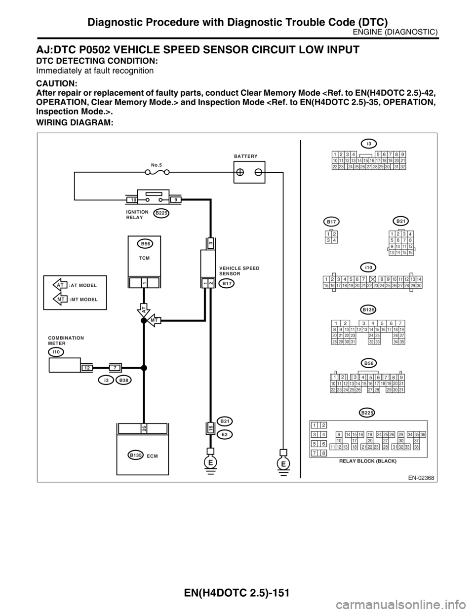
AJ:DTC P0502 VEHICLE SPEED SENSOR CIRCUIT LOW INPUT
DTC DETECTING CONDITION:
Immediately at fault recognition
CAUTION:
After repair or replacement of faulty parts, conduct Clear Memory Mode
OPERATION, Clear Memory Mode.> and Inspection Mode
Inspection Mode.>.
WIRING DIAGRAM:
EN-02368
i10
B135B21
123
4
56
78
9
1011 12
1314 15 16
B17
i3
567
82 1
94 310
24 22 23 2511 12 13 14 15
26 27
2816 17 18 19
20 21
29 30 31 32 33 34 35
E E
i10
B38
i3B17
E2 B21
B135B225 109
26
2
21
1
No.5
ECM
3
16
7
12
AT
:AT MODEL
MT
:MT MODEL
MT
AT
IGNITION
RELAYBATTERY
TCM
VEHICLE SPEED
SENSOR
COMBINATION
METERB56
3412
123456789101112131415161718192021222324252627282930
12
789 56 3
410 11 1219 20 21
29 30 31 13 14 15 1617
27 2818
22 23 24 25 26
B56
B225
RELAY BLOCK (BLACK)
10111213
1415161718
1920212223
2425262728
2930313233
3435363738
12
934
56
78
219
32
1234 5610 11 12 13 14 15716
23 3019 20
22 26 27 28 29817
24 3118
25
Page 2177 of 2870

EN(H4DOTC 2.5)-153
ENGINE (DIAGNOSTIC)
Diagnostic Procedure with Diagnostic Trouble Code (DTC)
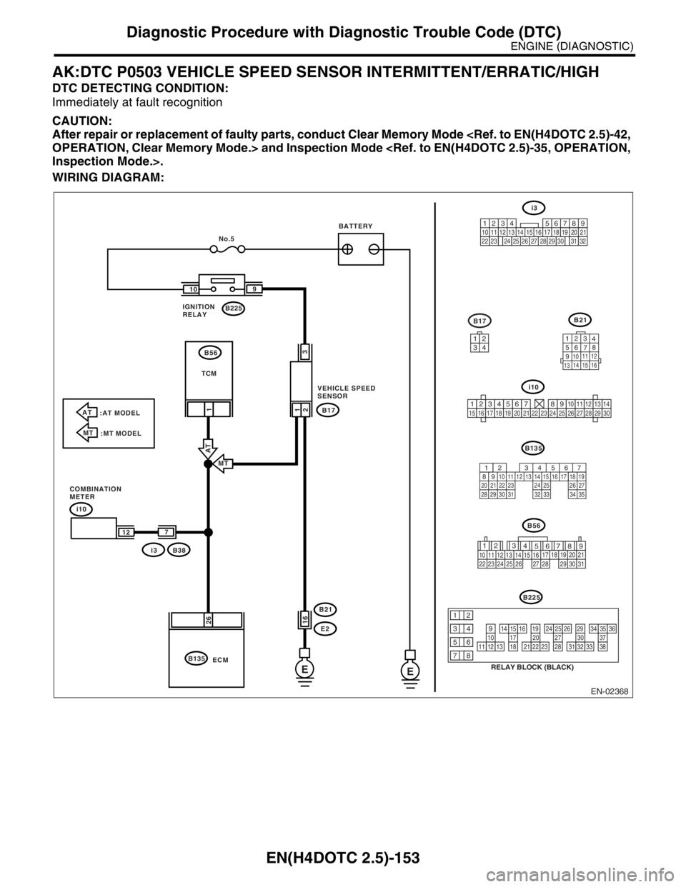
AK:DTC P0503 VEHICLE SPEED SENSOR INTERMITTENT/ERRATIC/HIGH
DTC DETECTING CONDITION:
Immediately at fault recognition
CAUTION:
After repair or replacement of faulty parts, conduct Clear Memory Mode
OPERATION, Clear Memory Mode.> and Inspection Mode
Inspection Mode.>.
WIRING DIAGRAM:
EN-02368
i10
B135B21
123
4
56
78
9
1011 12
1314 15 16
B17
i3
567
82 1
94 310
24 22 23 2511 12 13 14 15
26 27
2816 17 18 19
20 21
29 30 31 32 33 34 35
E E
i10
B38
i3B17
E2 B21
B135B225 109
26
2
21
1
No.5
ECM
3
16
7
12
AT
:AT MODEL
MT
:MT MODEL
MT
AT
IGNITION
RELAYBATTERY
TCM
VEHICLE SPEED
SENSOR
COMBINATION
METERB56
3412
123456789101112131415161718192021222324252627282930
12
789 56 3
410 11 1219 20 21
29 30 31 13 14 15 1617
27 2818
22 23 24 25 26
B56
B225
RELAY BLOCK (BLACK)
10111213
1415161718
1920212223
2425262728
2930313233
3435363738
12
934
56
78
219
32
1234 5610 11 12 13 14 15716
23 3019 20
22 26 27 28 29817
24 3118
25
Page 2179 of 2870
EN(H4DOTC 2.5)-155
ENGINE (DIAGNOSTIC)
Diagnostic Procedure with Diagnostic Trouble Code (DTC)
AL:DTC P0512 STARTER REQUEST CIRCUIT
DTC DETECTING CONDITION:
Immediately at fault recognition
TROUBLE SYMPTOM:
Failure of engine to start
CAUTION:
After repair or replacement of faulty parts, conduct Clear Memory Mode
OPERATION, Clear Memory Mode.> and Inspection Mode
Inspection Mode.>.
WIRING DIAGRAM:
EN-02311
BATTERY
INHIBITOR SWITCH
IGNITION
SWITCH
STARTER
MOTOR
SBF-4SBF-1
B72
B72
B14
B137
ECM
EE
1
3
D8
3412
B137
T3B12MT
AT
AT
MT
1112712
PR
N
D3
21
T7
B12
123
8
9
10
4
11
1256
7
T7
123
8910411 1256
7567
82 1
94 310
22 23 11 12 13 14 15
24 25
2616 17
18 19 20 21
27 28 29 30 31
Page 2234 of 2870
EN(H4DOTC 2.5)-210
ENGINE (DIAGNOSTIC)
Diagnostic Procedure with Diagnostic Trouble Code (DTC)
BQ:DTC P1518 STARTER SWITCH CIRCUIT LOW INPUT
DTC DETECTING CONDITION:
Two consecutive driving cycles with fault
TROUBLE SYMPTOM:
Failure of engine to start
CAUTION:
After repair or replacement of faulty parts, conduct Clear Memory Mode
OPERATION, Clear Memory Mode.> and Inspection Mode
Inspection Mode.>.
WIRING DIAGRAM:
EN-02311
BATTERY
INHIBITOR SWITCH
IGNITION
SWITCH
STARTER
MOTOR
SBF-4SBF-1
B72
B72
B14
B137
ECM
EE
1
3
D8
3412
B137
T3B12MT
AT
AT
MT
1112712
PR
N
D3
21
T7
B12
123
8
9
10
4
11
1256
7
T7
123
8910411 1256
7567
82 1
94 310
22 23 11 12 13 14 15
24 25
2616 17
18 19 20 21
27 28 29 30 31
Page 2238 of 2870
EN(H4DOTC 2.5)-214
ENGINE (DIAGNOSTIC)
Diagnostic Procedure with Diagnostic Trouble Code (DTC)
BS:DTC P1560 BACK-UP VOLTAGE CIRCUIT MALFUNCTION
DTC DETECTING CONDITION:
Immediately at fault recognition
CAUTION:
After repair or replacement of faulty parts, conduct Clear Memory Mode
OPERATION, Clear Memory Mode.> and Inspection Mode
Inspection Mode.>.
WIRING DIAGRAM:
EN-02356
B72
B135
3412
BATTERY MAIN RELAY
SBF-4 SBF-1SBF-5
B72
D16 D7
B12
A6
A7
B1
B4
D1
D2
A34B5
B6
B19
D14
No.11
B47
E2 B21 1 2 3 5 6 4
ECM
E
E
1 4
B134
B135
B137 A:
B:
D:
14133
15
16
34 12
56123
4
56
78
91011 12
1314 15 16
B134 B21 B47B137 A: D:
B: IGNITION
SWITCH
56 7
82 1
94 310
24 22 23 25 11 12 13 14 15
26 27
2816 17
18 19 20 21
33 34 29
32 30 31
567
82 1
94 310
24 22 23 2511 12 13 14 15
26 27
2816 17 18 19
20 21
29 30 31 32 33 34 35
567
82 1
94 310
22 23 11 12 13 14 15
24 25
2616 17
18 19 20 21
27 28 29 30 31
Page 2258 of 2870

EN(H4DOTC 2.5)-234
ENGINE (DIAGNOSTIC)
Diagnostic Procedure with Diagnostic Trouble Code (DTC)
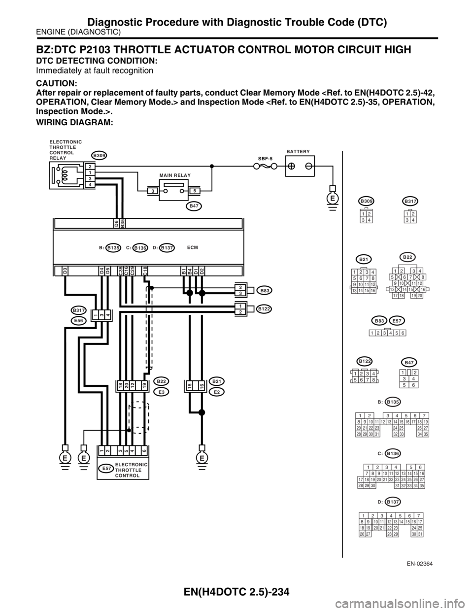
BZ:DTC P2103 THROTTLE ACTUATOR CONTROL MOTOR CIRCUIT HIGH
DTC DETECTING CONDITION:
Immediately at fault recognition
CAUTION:
After repair or replacement of faulty parts, conduct Clear Memory Mode
OPERATION, Clear Memory Mode.> and Inspection Mode
Inspection Mode.>.
WIRING DIAGRAM:
EN-02364
B317
34
12
B22
125678
131415169101112
34
17181920
B21
123
4
56
78
9
1011 12
1314 15 16
B83
1
23456
B135
567
82 1
94 3
10
24 22 23 2511 12 13 14 15
26 27
2816 17 18 19
20 21
29 30 31 32 33 34 35
B:
B35D6
B135 B: C:
D4 D3
C18
B1 C35
D1 B4
D2
SBF-5
2
1
3
4
E
E57
3
6 4
1
2 2
3
15
16
E
5
EE
B137 D:ECM B309
B136
B122
1
E2 B21
E3 B22 B317
E56B47 35
2 1
4 3
D5C16C29
19122018
MAIN RELAYBATTERY
ELECTRONIC
THROTTLE
CONTROL ELECTRONIC
THROTTLE
CONTROL
RELAY
B83
B122
123456783412
56
B47
B137
567
82 1
94 3
10
22 23 11 12 13 14 15
24 25
2616 17
18 19 20 21
27 28 29 30 31
D:
B136
56
782 1
94 3
10
24 22 23 2511 12 13
1415
26 27
2816
17 18 19 20 21
33 34 29
32 30
31 35
C:
B309
34
12
E57
Page 2292 of 2870

CS-7
CONTROL SYSTEM
General Description
C: CAUTION
Wear working clothing, including a cap, protec-
tive goggles, and protective shoes during opera-
tion.
Remove contamination including dirt and corro-
sion before removal, installation or disassembly.
Keep the disassembled parts in order and pro-
tect them from dust or dirt.
Before removal, installation or disassembly, be
sure to clarify the failure. Avoid unnecessary re-
moval, installation, disassembly and replacement.
Use SUBARU genuine fluid, grease etc. or the
equivalent. Do not mix grease etc. with that of an-
other grade or from other manufacturers.
Be sure to tighten fasteners including bolts and
nuts to the specified torque.
Place shop jacks or rigid racks at the specified
points.
Apply grease onto sliding or revolution surfaces
before installation.
Before installing O-rings or snap rings, apply suf-
ficient amount of grease to avoid damage and de-
formation.
Before securing a part on a vise, place cushion-
ing material such as wood blocks, aluminum plate,
or cloth between the part and vise.
Before disconnecting electrical connectors, be
sure to disconnect the ground cable from battery.
Page 2744 of 2870

5MT-32
MANUAL TRANSMISSION AND DIFFERENTIAL
Manual Transmission Assembly
3. Manual Transmission As-
sembly
A: REMOVAL
1) Set the vehicle on a lift.
2) Disconnect the ground cable from battery.
3) Drain the transmission gear oil completely.
to 5MT-31, REPLACEMENT, Transmission Gear
Oil.>
4) Open the front hood fully, and support with stay.
5) Remove the air intake duct and air cleaner case.
(Non-turbo model)
AL, Air Intake Duct.>
MOVAL, Air Cleaner Case.>
6) Remove the air cleaner case stay. (Non-turbo
model)
7) Remove the intercooler. (Turbo model)
IN(H4DOTC)-10, REMOVAL, Intercooler.>
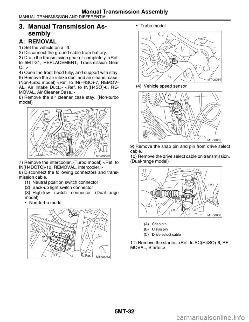
8) Disconnect the following connectors and trans-
mission cable.
(1) Neutral position switch connector
(2) Back-up light switch connector
(3) High-low switch connector (Dual-range
model)
Non-turbo model Turbo model
(4) Vehicle speed sensor
9) Remove the snap pin and pin from drive select
cable.
10) Remove the drive select cable on transmission.
(Dual-range model)
11) Remove the starter.
MOVAL, Starter.>
ME-00062
MT-00063
(A) Snap pin
(B) Clevis pin
(C) Drive select cable
MT-00064
MT-00065
MT-00066
(A)
(B)
(C)