Page 2389 of 2870

4AT-76
AUTOMATIC TRANSMISSION
ATF Filter
21.ATF Filter
A: REMOVAL
NOTE:
The ATF filter is maintenance free.
1) Lift-up the vehicle.
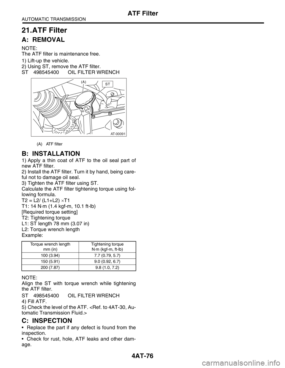
2) Using ST, remove the ATF filter.
ST 498545400 OIL FILTER WRENCH
B: INSTALLATION
1) Apply a thin coat of ATF to the oil seal part of
new ATF filter.
2) Install the ATF filter. Turn it by hand, being care-
ful not to damage oil seal.
3) Tighten the ATF filter using ST.
Calculate the ATF filter tightening torque using fol-
lowing formula.
T2 = L2/ (L1+L2) ×T1
T1: 14 N⋅m (1.4 kgf-m, 10.1 ft-lb)
[Required torque setting]
T2: Tightening torque
L1: ST length 78 mm (3.07 in)
L2: Torque wrench length
Example:
NOTE:
Align the ST with torque wrench while tightening
the ATF filter.
ST 498545400 OIL FILTER WRENCH
4) Fill ATF.
5) Check the level of the ATF.
tomatic Transmission Fluid.>
C: INSPECTION
Replace the part if any defect is found from the
inspection.
Check for rust, hole, ATF leaks and other dam-
age.
(A) ATF filter
Torque wrench length
mm (in)Tightening torque
N⋅m (kgf-m, ft-lb)
100 (3.94) 7.7 (0.79, 5.7)
150 (5.91) 9.0 (0.92, 6.7)
200 (7.87) 9.8 (1.0, 7.2)
AT-00091
(A)ST
Page 2390 of 2870
4AT-77
AUTOMATIC TRANSMISSION
Transmission Control Module (TCM)
22.Transmission Control Mod-
ule (TCM)
A: REMOVAL
1) Disconnect the ground cable from battery.
2) Remove the lower cover and then disconnect
the connector.
3) Disconnect the connectors from TCM.
LHD model
RHD model
4) Remove the TCM.
B: INSTALLATION
1) Install the TCM.
LHD model
Tightening torque:
25 N
⋅m (2.5 kgf-m, 18.1 ft-lb)
RHD model
Tightening torque:
18 N
⋅m (1.8 kgf-m, 13.0 ft-lb)
2) Connect the connectors to TCM.
3) Install in the reverse order of removal.
(A) Transmission control module (TCM)
(B) Brake pedal
(A) Transmission control module (TCM)
(B) Steering column
AT-00041
(A)
(B)
AT-00748
AT-00749
(A)(B)
(A) Transmission control module (TCM)
(B) Brake pedal
(A) Transmission control module (TCM)
(B) Steering column
(A)
(B)
AT-00748
AT-00749
(A)(B)
Page 2391 of 2870
4AT-78
AUTOMATIC TRANSMISSION
Dropping Resistor
23.Dropping Resistor
A: REMOVAL
1) Disconnect the ground cable from battery.
2) Disconnect the connector from dropping resis-
tor.
3) Remove the dropping resistor.
B: INSTALLATION
Install in the reverse order of removal.
Tightening torque:
6.4 N
⋅m (0.65 kgf-m, 4.7 ft-lb)
C: INSPECTION
(A) Dropping resistor
AT-00041
AT-00313
(A)
(A) Dropping resistor
AT-00313
(A)
Step Check Yes No
1 CHECK RESISTOR.
1) Turn the ignition switch to OFF.
2) Disconnect the connector from dropping
resistor.
3) Measure the resistance between dropping
resistors.
Te r m i n a l s
No. 1 — No. 2:Is the resistance 9 — 15 Ω? Go to step 2.Replace the drop-
ping resistor.
to 4AT-78, Drop-
ping Resistor.>
2 CHECK RESISTOR.
Measure the resistance between dropping
resistors.
Te r m i n a l s
No. 3 — No. 4:Is the resistance 9 — 15 Ω? Dropping resistor
is normal.Replace the drop-
ping resistor.
to 4AT-78, Drop-
ping Resistor.>
Page 2392 of 2870

4AT-79
AUTOMATIC TRANSMISSION
ATF Cooler Pipe and Hose
24.ATF Cooler Pipe and Hose
A: REMOVAL
1. EXCEPT WITH ATF COOLER MODEL
(WITH WARMER FUNCTION)
1) Set the vehicle on a lift.
2) Remove the battery and washer tank.
3) Lift-up the vehicle.
4) Remove the under cover.
5) Disconnect the ATF cooler hose from radiator.
(Turbo model)
AL, Radiator.>
6) Disconnect the ATF cooler hose from radiator.
(Non-turbo model)
NOTE:
Do not use a screwdriver or other pointed tools.
When hard to remove the hose, wrap the hose
with cloth to prevent from damaging, and then turn
with pliers and pull out with hand straightly.
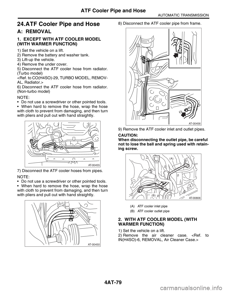
7) Disconnect the ATF cooler hoses from pipes.
NOTE:
Do not use a screwdriver or other pointed tools.
When hard to remove the hose, wrap the hose
with cloth to prevent from damaging, and then turn
with pliers and pull out with hand straightly.8) Disconnect the ATF cooler pipe from frame.
9) Remove the ATF cooler inlet and outlet pipes.
CAUTION:
When disconnecting the outlet pipe, be careful
not to lose the ball and spring used with retain-
ing screw.
2. WITH ATF COOLER MODEL (WITH
WARMER FUNCTION)
1) Set the vehicle on a lift.
2) Remove the air cleaner case.
IN(H4SO)-6, REMOVAL, Air Cleaner Case.>
AT-00455
AT-00450
(A) ATF cooler inlet pipe
(B) ATF cooler outlet pipe
AT-00456
AT-00806
(A)
(B)
Page 2393 of 2870
4AT-80
AUTOMATIC TRANSMISSION
ATF Cooler Pipe and Hose
3) Remove the inlet and outlet hoses.
4) Disconnect the transmission harness connector
and remove it from the stay.
5) Remove the oil charger pipe.
REMOVAL, Oil Charger Pipe.>
6) Remove the ATF cooler assembly and away
from the transmission body.
7) Remove the air breather hose.
REMOVAL, Air Breather Hose.>8) Remove the oil cooler inlet and outlet pipes.
CAUTION:
When disconnecting the outlet pipe, be careful
not to lose the ball and spring used with retain-
ing screw.
(A) Inlet hose
(B) Outlet hose
AT-01866(A)(B)
AT-01868
(A) ATF cooler outlet pipe
(B) ATF cooler inlet pipe
AT-01870
(A)
(B)
(A)(B)
Page 2394 of 2870

4AT-81
AUTOMATIC TRANSMISSION
ATF Cooler Pipe and Hose
B: INSTALLATION
1. EXCEPT WITH ATF COOLER MODEL
(WITH WARMER FUNCTION)
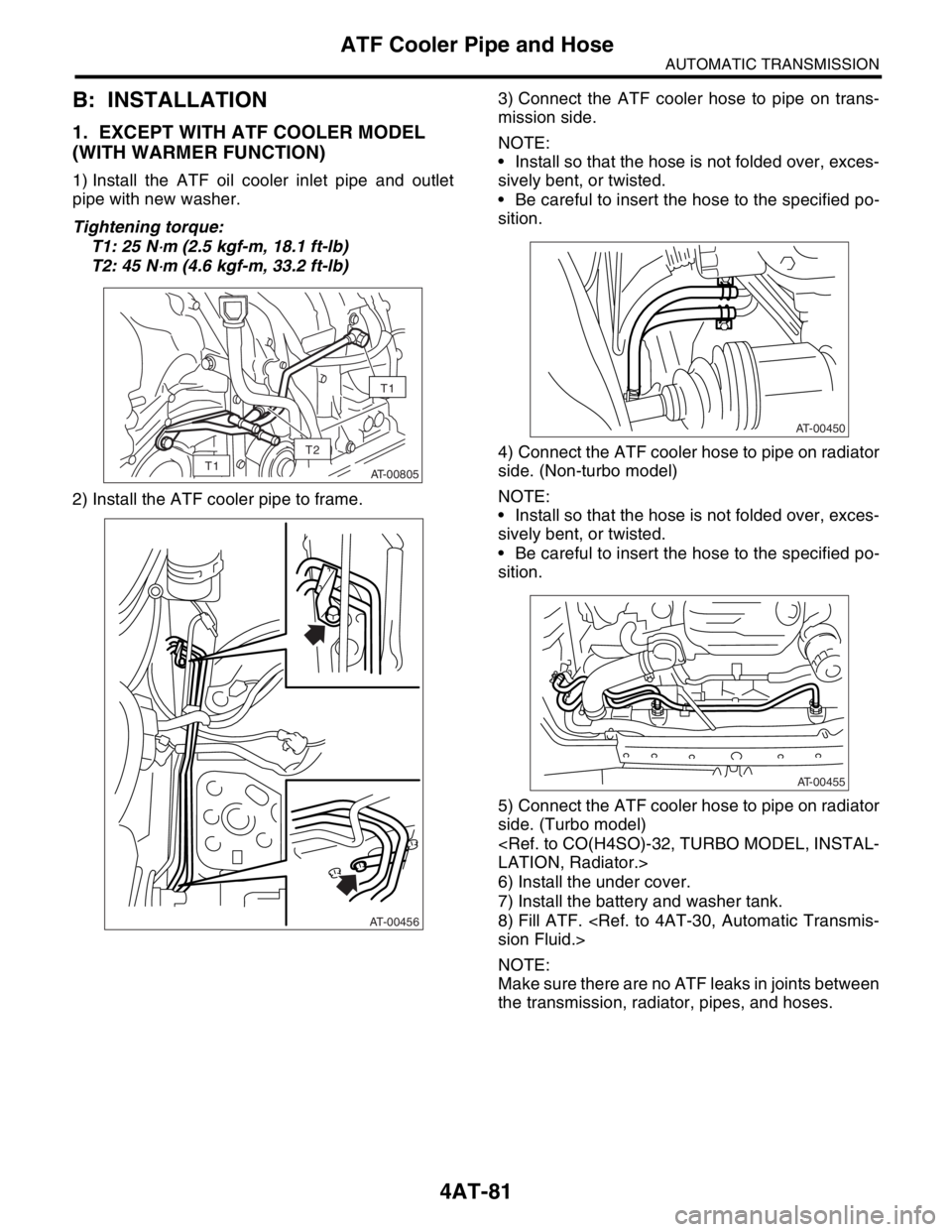
1) Install the ATF oil cooler inlet pipe and outlet
pipe with new washer.
Tightening torque:
T1: 25 N
⋅m (2.5 kgf-m, 18.1 ft-lb)
T2: 45 N
⋅m (4.6 kgf-m, 33.2 ft-lb)
2) Install the ATF cooler pipe to frame.3) Connect the ATF cooler hose to pipe on trans-
mission side.
NOTE:
Install so that the hose is not folded over, exces-
sively bent, or twisted.
Be careful to insert the hose to the specified po-
sition.
4) Connect the ATF cooler hose to pipe on radiator
side. (Non-turbo model)
NOTE:
Install so that the hose is not folded over, exces-
sively bent, or twisted.
Be careful to insert the hose to the specified po-
sition.
5) Connect the ATF cooler hose to pipe on radiator
side. (Turbo model)
LATION, Radiator.>
6) Install the under cover.
7) Install the battery and washer tank.
8) Fill ATF.
sion Fluid.>
NOTE:
Make sure there are no ATF leaks in joints between
the transmission, radiator, pipes, and hoses.
AT-00805
T1
T1
T2
AT-00456
AT-00450
AT-00455
Page 2395 of 2870

4AT-82
AUTOMATIC TRANSMISSION
ATF Cooler Pipe and Hose
2. WITH ATF COOLER MODEL (WITH
WARMER FUNCTION)
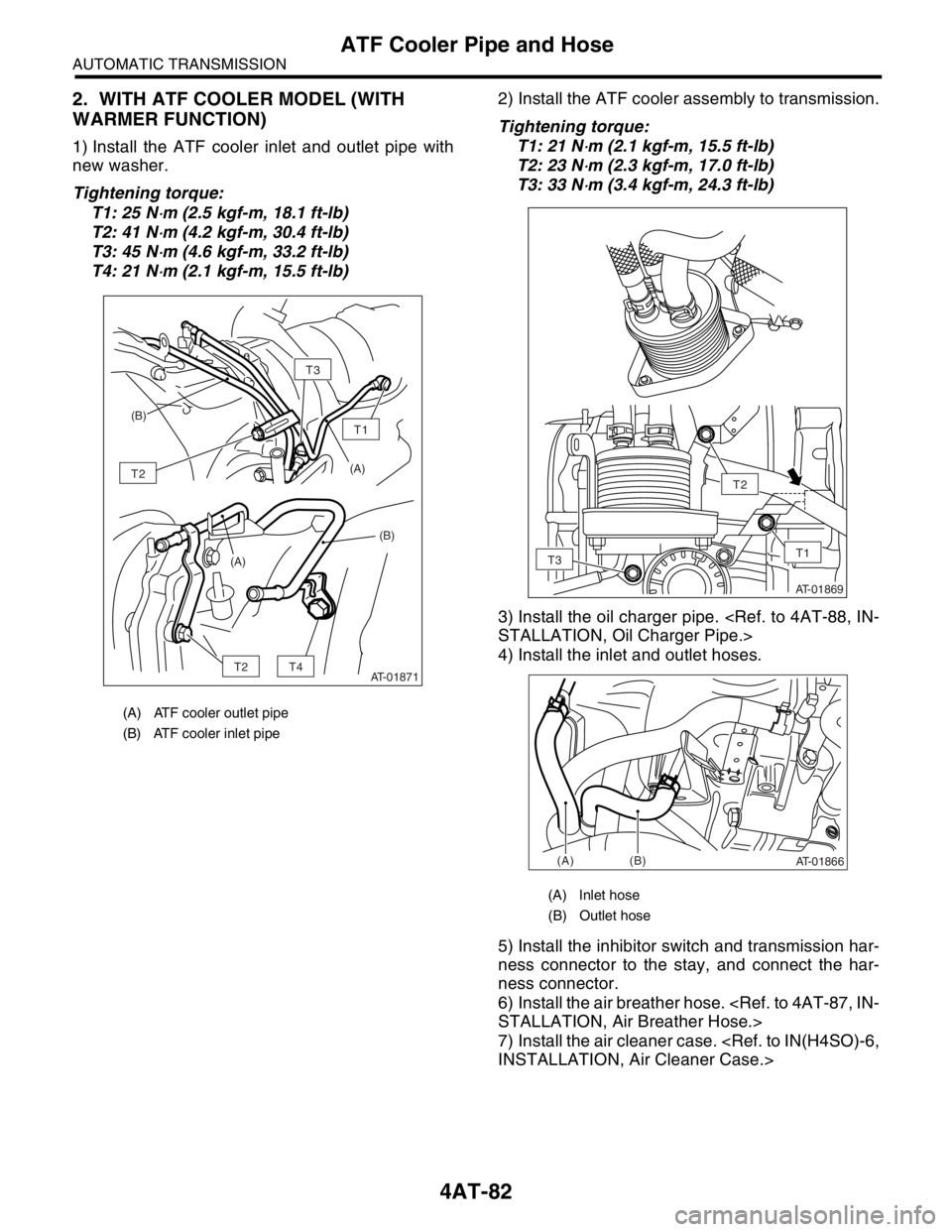
1) Install the ATF cooler inlet and outlet pipe with
new washer.
Tightening torque:
T1: 25 N
⋅m (2.5 kgf-m, 18.1 ft-lb)
T2: 41 N
⋅m (4.2 kgf-m, 30.4 ft-lb)
T3: 45 N
⋅m (4.6 kgf-m, 33.2 ft-lb)
T4: 21 N
⋅m (2.1 kgf-m, 15.5 ft-lb)2) Install the ATF cooler assembly to transmission.
Tightening torque:
T1: 21 N
⋅m (2.1 kgf-m, 15.5 ft-lb)
T2: 23 N
⋅m (2.3 kgf-m, 17.0 ft-lb)
T3: 33 N
⋅m (3.4 kgf-m, 24.3 ft-lb)
3) Install the oil charger pipe.
STALLATION, Oil Charger Pipe.>
4) Install the inlet and outlet hoses.
5) Install the inhibitor switch and transmission har-
ness connector to the stay, and connect the har-
ness connector.
6) Install the air breather hose.
STALLATION, Air Breather Hose.>
7) Install the air cleaner case.
INSTALLATION, Air Cleaner Case.>
(A) ATF cooler outlet pipe
(B) ATF cooler inlet pipe
AT-01871
T1
T2
T3
T4T2
(B)
(A)
(A)(B)
(A) Inlet hose
(B) Outlet hose
AT-01869
T2
T1T3
AT-01866(A)(B)
Page 2396 of 2870
4AT-83
AUTOMATIC TRANSMISSION
ATF Cooler Pipe and Hose
C: INSPECTION
Repair or replace any defective hoses, pipes,
clamps, and washers found from the inspection be-
low.
1) Check for ATF leaks in joints between the trans-
mission, radiator, pipes, and hoses.
2) Check for deformed clamps.
3) Lightly bend the hose and check for cracks in the
surface and other damage.
4) Pinch the hose with your fingers and check for
poor elasticity. Also check for poor elasticity in the
parts where the clamp was installed by pressing
with your fingernail.
5) Check for peeling, cracks, and deformation at
the tip of the hose.