2004 SUBARU FORESTER automatic transmission
[x] Cancel search: automatic transmissionPage 692 of 2870

SPC-3
SPECIFICATION
Forester
C: ELECTRICAL
★: For Australia model
D: TRANSMISSION
5MT: 5 forward speeds with synchromesh and 1-reverse
4AT: Electronically controlled fully-automatic, 4-forward speeds and 1-reverse
DSPD: Dry Single Plate Diaphragm
TCC: Torque Converter Clutch
★: For Europe model
E: STEERING
Model 2.0 L Non-turbo 2.0 L Turbo 2.5 L Non-turbo 2.5 L Turbo
Ignition timing at idling speed BTDC/rpm 10°±10°/650 12°±10°/700MT: 10°±10°/650
AT : 1 5°±10°/65017°±10°/700
Spark plug Type and manufacturerCHAMPION:
RC10YC4
NGK: PFR6GCHAMPION:
RC10YC4
NGK: ILFR6B
Alternate
NGK: BKR5E-11Alternate
NGK: BKR5E-11
Generator12 V — 90 A
Battery Type and capacity (5HR)MT: 12 V — 48 AH (55D23L)
AT: 12 V — 52 AH (65D23L)12 V — 27 AH
(34B19L)
12 V — 48 AH
(55D23L)
★
MT: 12 V — 48
AH (55D23L)
AT: 12 V — 52
AH (65D23L)
Model 2.0 L Non-turbo 2.0 L Turbo 2.5 L Non-turbo 2.5 L Turbo
Transmission type 5MT 4AT 5MT 4AT 5MT 4AT 5MT 4AT
Clutch type DSPD TCC DSPD TCC DSPD TCC DSPD TCC
Gear ratio1st 3.454 2.785 3.454 2.785 3.454 2.785 3.454 2.785
2nd 2.062 1.545 1.947 1.545 2.062 1.545 1.947 1.545
3rd 1.448 1.000 1.366 1.000 1.448 1.000 1.366 1.000
4th 1.088 0.694 0.972 0.694 1.088 0.694 0.972 0.694
5th 0.871 — 0.738 — 0.780 — 0.738 —
Reverse 3.333 2.272 3.333 2.272 3.333 2.272 3.333 2.272
Dual range 1.447 — — — 1.196 — — —
Reduction
gear (Front)1st reduc-
tionType of gear — Helical — Helical — Helical — Helical
Gear ratio — 1.000 — 1.000 — 1.000 — 1.000
Final reduc-
tionType of gear Hypoid
Gear ratio 4.111 4.444 4.444 4.111 4.111 4.444 4.111 4.444
Reduction
gear (Rear)Transfer
reductionType of gear Helical — Helical — Helical — Helical —
Gear ratio 1.000 —1.081
★,
1.000— 1.000 — 1.000 —
Final reduc-
tionType of gear Hypoid
Gear ratio 4.111 4.4444.111
★,
4.4444.111 4.111 4.444 4.111 4.444
Ty p eRack and Pinion, Integral
Turns, lock to lock3.0
Minimum turning circle m (ft)Curb to curb 10.6 (34.8)
Wall to wall 11.4 (37.4)
Page 720 of 2870
RM-5
RECOMMENDED MATERIAL
Recommended Materials
4. FLUID
Use the fluids specified in the table below. Do not mix two different kinds or makes of fluid.
5. COOLANT
Use genuine coolant to protect the engine.
6. REFRIGERANT
Standard air conditioners on Subaru vehicles use HFC134a refrigerant. Do not mix it with other refrigerants.
Also, do not use any air compressor oil except for ZXL200PG.
7. GREASE
Use the grease and supplementary lubricants shown in the table below.
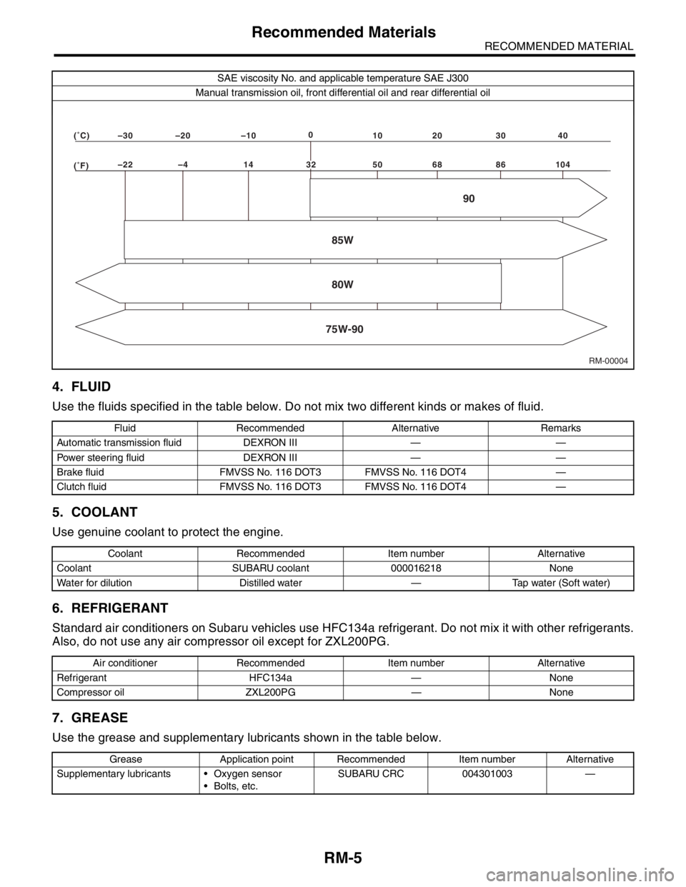
SAE viscosity No. and applicable temperature SAE J300
Manual transmission oil, front differential oil and rear differential oil
Fluid Recommended Alternative Remarks
Automatic transmission fluid DEXRON III — —
Power steering fluid DEXRON III — —
Brake fluid FMVSS No. 116 DOT3 FMVSS No. 116 DOT4 —
Clutch fluid FMVSS No. 116 DOT3 FMVSS No. 116 DOT4 —
Coolant Recommended Item number Alternative
Coolant SUBARU coolant 000016218 None
Water for dilution Distilled water — Tap water (Soft water)
Air conditioner Recommended Item number Alternative
Refrigerant HFC134a — None
Compressor oil ZXL200PG — None
Grease Application point Recommended Item number Alternative
Supplementary lubricants Oxygen sensor
Bolts, etc.SUBARU CRC 004301003 —
RM-00004 (�F)–22 –4 14 50 68 86 104 (�C)–30 –20 –100
10 20 30 40
85W
75W-9080W90
32
Page 763 of 2870
PM-26
PERIODIC MAINTENANCE SERVICE
ATF
16.ATF
A: INSPECTION
CAUTION:
The level of ATF varies with fluid temperature.
Pay attention to the fluid temperature when
checking ATF level.
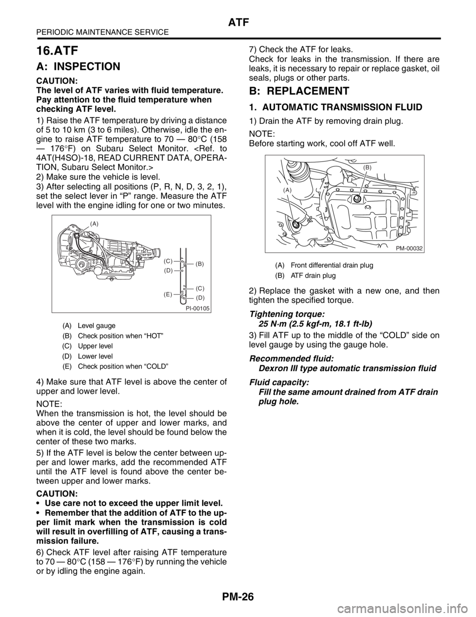
1) Raise the ATF temperature by driving a distance
of 5 to 10 km (3 to 6 miles). Otherwise, idle the en-
gine to raise ATF temperature to 70 — 80°C (158
— 176°F) on Subaru Select Monitor.
TION, Subaru Select Monitor.>
2) Make sure the vehicle is level.
3) After selecting all positions (P, R, N, D, 3, 2, 1),
set the select lever in “P” range. Measure the ATF
level with the engine idling for one or two minutes.
4) Make sure that ATF level is above the center of
upper and lower level.
NOTE:
When the transmission is hot, the level should be
above the center of upper and lower marks, and
when it is cold, the level should be found below the
center of these two marks.
5) If the ATF level is below the center between up-
per and lower marks, add the recommended ATF
until the ATF level is found above the center be-
tween upper and lower marks.
CAUTION:
Use care not to exceed the upper limit level.
Remember that the addition of ATF to the up-
per limit mark when the transmission is cold
will result in overfilling of ATF, causing a trans-
mission failure.
6) Check ATF level after raising ATF temperature
to 70 — 80°C (158 — 176°F) by running the vehicle
or by idling the engine again.7) Check the ATF for leaks.
Check for leaks in the transmission. If there are
leaks, it is necessary to repair or replace gasket, oil
seals, plugs or other parts.
B: REPLACEMENT
1. AUTOMATIC TRANSMISSION FLUID
1) Drain the ATF by removing drain plug.
NOTE:
Before starting work, cool off ATF well.
2) Replace the gasket with a new one, and then
tighten the specified torque.
Tightening torque:
25 N·m (2.5 kgf-m, 18.1 ft-lb)
3) Fill ATF up to the middle of the “COLD” side on
level gauge by using the gauge hole.
Recommended fluid:
Dexron III type automatic transmission fluid
Fluid capacity:
Fill the same amount drained from ATF drain
plug hole.
(A) Level gauge
(B) Check position when “HOT”
(C) Upper level
(D) Lower level
(E) Check position when “COLD”
PI-00105
COLD
LFHOT LF
(A)
(C)
(D)
(C)
(D)
(E)
(B)(A) Front differential drain plug
(B) ATF drain plug
PM-00032
(B)
(A)
Page 885 of 2870
ME(H4SO)-16
MECHANICAL
General Description
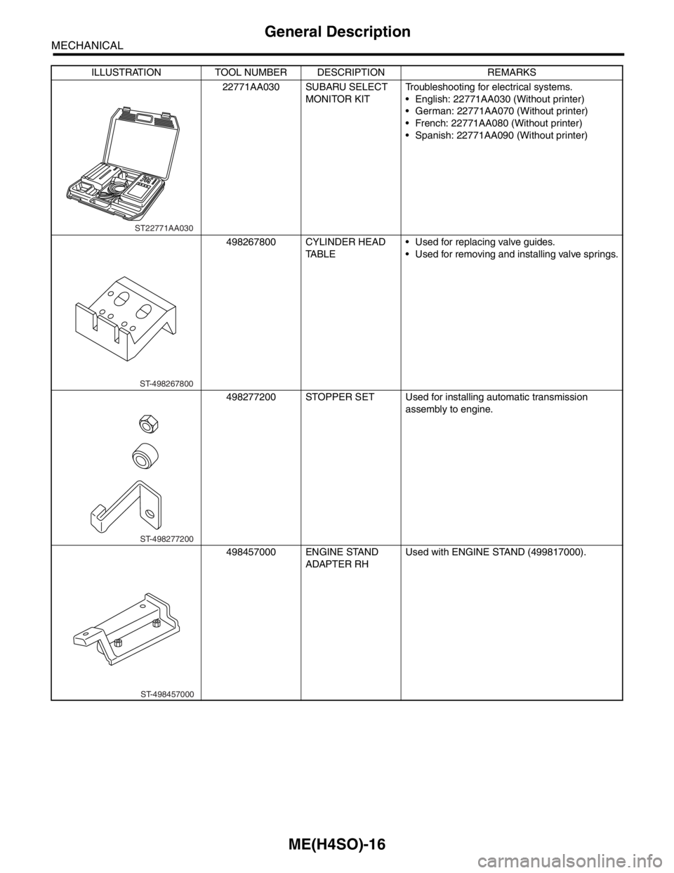
22771AA030 SUBARU SELECT
MONITOR KITTroubleshooting for electrical systems.
English: 22771AA030 (Without printer)
German: 22771AA070 (Without printer)
French: 22771AA080 (Without printer)
Spanish: 22771AA090 (Without printer)
498267800 CYLINDER HEAD
TABLE Used for replacing valve guides.
Used for removing and installing valve springs.
498277200 STOPPER SET Used for installing automatic transmission
assembly to engine.
498457000 ENGINE STAND
ADAPTER RHUsed with ENGINE STAND (499817000). ILLUSTRATION TOOL NUMBER DESCRIPTION REMARKS
ST22771AA030
ST-498267800
ST-498277200
ST-498457000
Page 1014 of 2870
CO(H4SO)-31
COOLING
Radiator
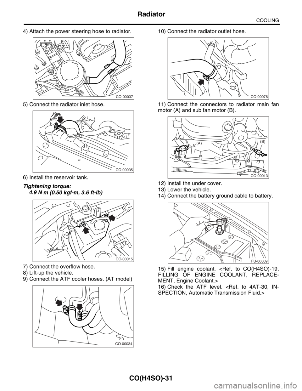
4) Attach the power steering hose to radiator.
5) Connect the radiator inlet hose.
6) Install the reservoir tank.
Tightening torque:
4.9 N
⋅m (0.50 kgf-m, 3.6 ft-lb)
7) Connect the overflow hose.
8) Lift-up the vehicle.
9) Connect the ATF cooler hoses. (AT model)10) Connect the radiator outlet hose.
11) Connect the connectors to radiator main fan
motor (A) and sub fan motor (B).
12) Install the under cover.
13) Lower the vehicle.
14) Connect the battery ground cable to battery.
15) Fill engine coolant.
MENT, Engine Coolant.>
16) Check the ATF level.
CO-00037
CO-00035
CO-00015
CO-00034
CO-00076
CO-00013
(A)(B)
FU-00009
Page 1016 of 2870
CO(H4SO)-33
COOLING
Radiator
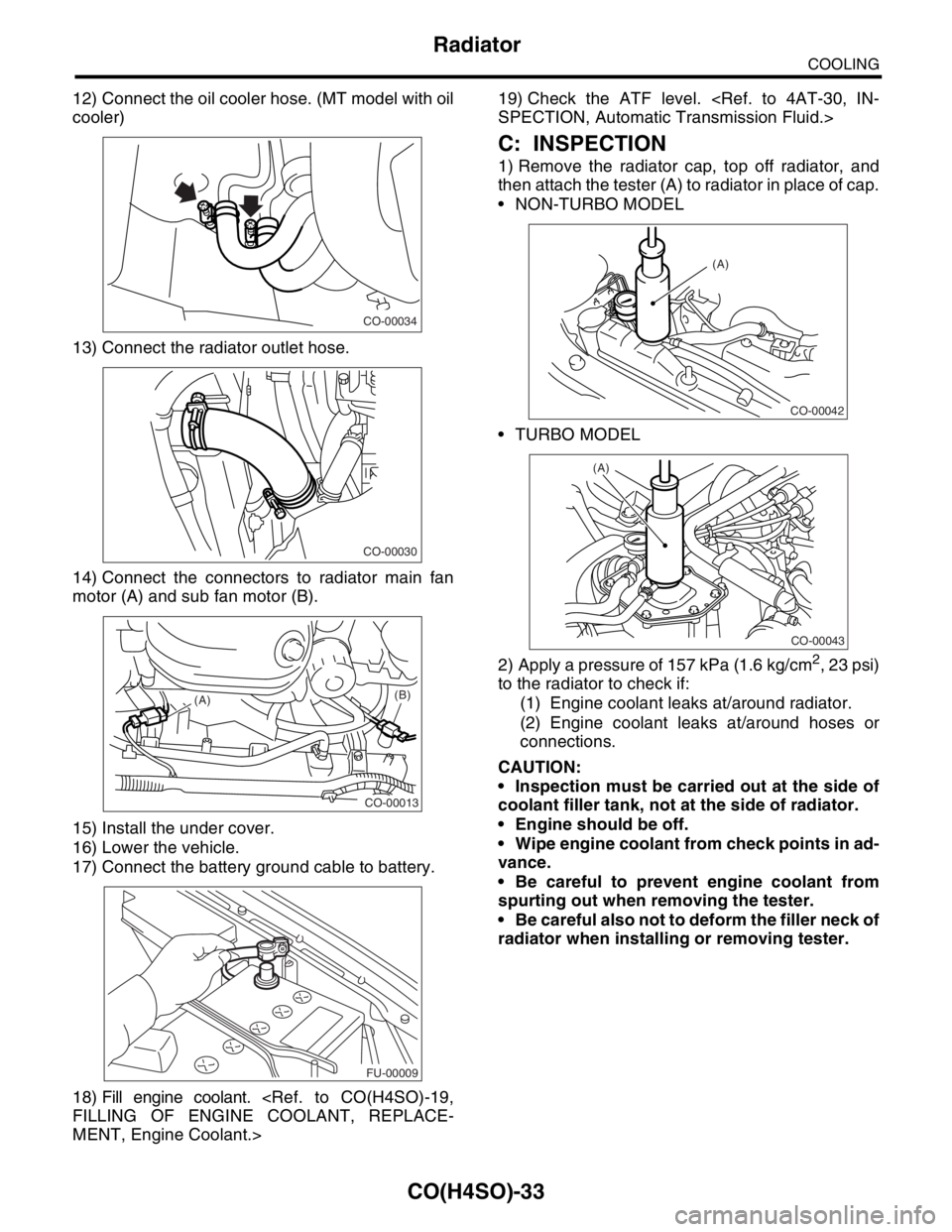
12) Connect the oil cooler hose. (MT model with oil
cooler)
13) Connect the radiator outlet hose.
14) Connect the connectors to radiator main fan
motor (A) and sub fan motor (B).
15) Install the under cover.
16) Lower the vehicle.
17) Connect the battery ground cable to battery.
18) Fill engine coolant.
MENT, Engine Coolant.>19) Check the ATF level.
C: INSPECTION
1) Remove the radiator cap, top off radiator, and
then attach the tester (A) to radiator in place of cap.
NON-TURBO MODEL
TURBO MODEL
2) Apply a pressure of 157 kPa (1.6 kg/cm
2, 23 psi)
to the radiator to check if:
(1) Engine coolant leaks at/around radiator.
(2) Engine coolant leaks at/around hoses or
connections.
CAUTION:
Inspection must be carried out at the side of
coolant filler tank, not at the side of radiator.
Engine should be off.
Wipe engine coolant from check points in ad-
vance.
Be careful to prevent engine coolant from
spurting out when removing the tester.
Be careful also not to deform the filler neck of
radiator when installing or removing tester.
CO-00034
CO-00030
CO-00013
(A)(B)
FU-00009
CO-00042
(A)
CO-00043
(A)
Page 1101 of 2870

EN(H4SO)-3
ENGINE (DIAGNOSTIC)
Basic Diagnostics Procedure
2. AUTOMATIC TRANSMISSION
When the DTC about automatic transmission is
shown on display, carry out the following basic
check. After that, carry out the replacement or re-
pair work.
1) ATF level check
2) Differential gear oil level check
3) ATF leak check
4) Differential gear oil level check
5) Stall Test
6) Line Pressure Test
7) Transfer Clutch Pressure Test
8) Time Lag Test
9) Road Test
10) Shift characteristics
Page 1105 of 2870
EN(H4SO)-7
ENGINE (DIAGNOSTIC)
General Description
The antenna feeder must be placed as far
apart as possible from the ECM and MFI har-
ness.
Carefully adjust the antenna for correct
matching.
When mounting a large power type radio, pay
special attention to the three items above men-
tioned.
Incorrect installation of the radio may affect
the operation of the ECM.
13) Before disconnecting the fuel hose, disconnect
the fuel pump connector and crank the engine for
more than five seconds to release pressure in the
fuel system. If engine starts during this operation,
run it until it stops.
14) Problems in the electronic-controlled automatic
transmission may be caused by failure of the en-
gine, the electronic control system, the transmis-
sion proper, or by a combination of these. These
three causes must be distinguished clearly when
performing diagnostics.
15) Diagnostics should be conducted by rotating
with simple, easy operations and proceeding to
complicated, difficult operations. The most impor-
tant thing in diagnostics is to understand the cus-
tomer’s complaint, and distinguish between the
three causes.
16) In AT models, do not continue the stall for more
than five seconds. (from closed throttle, fully open
throttle to stall engine speed.)
17) On the model with ABS, when performing driv-
ing test in jacked-up or lifted-up position, some-
times the warning light may be lit, but this is not a
malfunction of the system. The reason for this is the
speed difference between the front and rear
wheels. After diagnosis of engine control system,
perform the ABS memory clearance procedure of
self-diagnosis function.
B: INSPECTION
Before performing diagnostics, check the following
items which might affect engine problems:
1. BATTERY
1) Measure battery voltage and specific gravity of
electrolyte.
Standard voltage: 12 V
Specific gravity: Above 1.260
2) Check the condition of the main and other fuses,
and harnesses and connectors. Also check for
proper grounding.
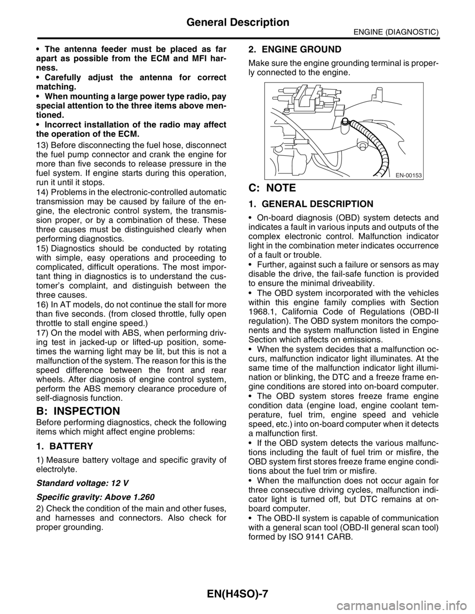
2. ENGINE GROUND
Make sure the engine grounding terminal is proper-
ly connected to the engine.
C: NOTE
1. GENERAL DESCRIPTION
On-board diagnosis (OBD) system detects and
indicates a fault in various inputs and outputs of the
complex electronic control. Malfunction indicator
light in the combination meter indicates occurrence
of a fault or trouble.
Further, against such a failure or sensors as may
disable the drive, the fail-safe function is provided
to ensure the minimal driveability.
The OBD system incorporated with the vehicles
within this engine family complies with Section
1968.1, California Code of Regulations (OBD-II
regulation). The OBD system monitors the compo-
nents and the system malfunction listed in Engine
Section which affects on emissions.
When the system decides that a malfunction oc-
curs, malfunction indicator light illuminates. At the
same time of the malfunction indicator light illumi-
nation or blinking, the DTC and a freeze frame en-
gine conditions are stored into on-board computer.
The OBD system stores freeze frame engine
condition data (engine load, engine coolant tem-
perature, fuel trim, engine speed and vehicle
speed, etc.) into on-board computer when it detects
a malfunction first.
If the OBD system detects the various malfunc-
tions including the fault of fuel trim or misfire, the
OBD system first stores freeze frame engine condi-
tions about the fuel trim or misfire.
When the malfunction does not occur again for
three consecutive driving cycles, malfunction indi-
cator light is turned off, but DTC remains at on-
board computer.
The OBD-II system is capable of communication
with a general scan tool (OBD-II general scan tool)
formed by ISO 9141 CARB.
EN-00153