2004 SUBARU FORESTER automatic transmission
[x] Cancel search: automatic transmissionPage 1637 of 2870

EN(H4DOTC)-7
ENGINE (DIAGNOSTIC)
General Description
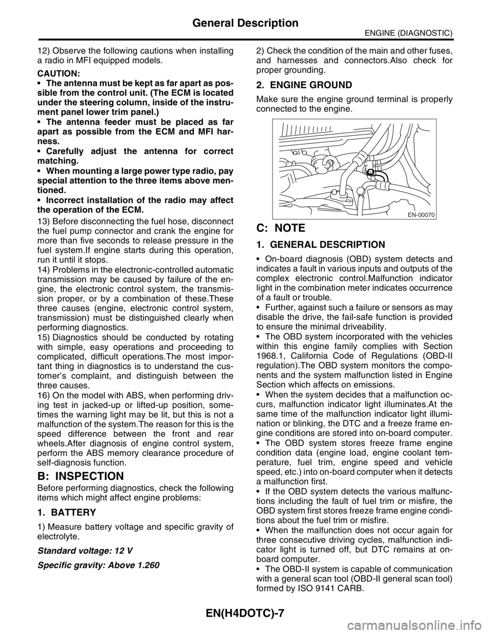
12) Observe the following cautions when installing
a radio in MFI equipped models.
CAUTION:
The antenna must be kept as far apart as pos-
sible from the control unit. (The ECM is located
under the steering column, inside of the instru-
ment panel lower trim panel.)
The antenna feeder must be placed as far
apart as possible from the ECM and MFI har-
ness.
Carefully adjust the antenna for correct
matching.
When mounting a large power type radio, pay
special attention to the three items above men-
tioned.
Incorrect installation of the radio may affect
the operation of the ECM.
13) Before disconnecting the fuel hose, disconnect
the fuel pump connector and crank the engine for
more than five seconds to release pressure in the
fuel system.If engine starts during this operation,
run it until it stops.
14) Problems in the electronic-controlled automatic
transmission may be caused by failure of the en-
gine, the electronic control system, the transmis-
sion proper, or by a combination of these.These
three causes (engine, electronic control system,
transmission) must be distinguished clearly when
performing diagnostics.
15) Diagnostics should be conducted by rotating
with simple, easy operations and proceeding to
complicated, difficult operations.The most impor-
tant thing in diagnostics is to understand the cus-
tomer’s complaint, and distinguish between the
three causes.
16) On the model with ABS, when performing driv-
ing test in jacked-up or lifted-up position, some-
times the warning light may be lit, but this is not a
malfunction of the system.The reason for this is the
speed difference between the front and rear
wheels.After diagnosis of engine control system,
perform the ABS memory clearance procedure of
self-diagnosis function.
B: INSPECTION
Before performing diagnostics, check the following
items which might affect engine problems:
1. BATTERY
1) Measure battery voltage and specific gravity of
electrolyte.
Standard voltage: 12 V
Specific gravity: Above 1.2602) Check the condition of the main and other fuses,
and harnesses and connectors.Also check for
proper grounding.
2. ENGINE GROUND
Make sure the engine ground terminal is properly
connected to the engine.
C: NOTE
1. GENERAL DESCRIPTION
On-board diagnosis (OBD) system detects and
indicates a fault in various inputs and outputs of the
complex electronic control.Malfunction indicator
light in the combination meter indicates occurrence
of a fault or trouble.
Further, against such a failure or sensors as may
disable the drive, the fail-safe function is provided
to ensure the minimal driveability.
The OBD system incorporated with the vehicles
within this engine family complies with Section
1968.1, California Code of Regulations (OBD-II
regulation).The OBD system monitors the compo-
nents and the system malfunction listed in Engine
Section which affects on emissions.
When the system decides that a malfunction oc-
curs, malfunction indicator light illuminates.At the
same time of the malfunction indicator light illumi-
nation or blinking, the DTC and a freeze frame en-
gine conditions are stored into on-board computer.
The OBD system stores freeze frame engine
condition data (engine load, engine coolant tem-
perature, fuel trim, engine speed and vehicle
speed, etc.) into on-board computer when it detects
a malfunction first.
If the OBD system detects the various malfunc-
tions including the fault of fuel trim or misfire, the
OBD system first stores freeze frame engine condi-
tions about the fuel trim or misfire.
When the malfunction does not occur again for
three consecutive driving cycles, malfunction indi-
cator light is turned off, but DTC remains at on-
board computer.
The OBD-II system is capable of communication
with a general scan tool (OBD-II general scan tool)
formed by ISO 9141 CARB.
EN-00070
Page 1668 of 2870
![SUBARU FORESTER 2004 Service Repair Manual EN(H4DOTC)-38
ENGINE (DIAGNOSTIC)
Subaru Select Monitor
8. READ CURRENT DATA FOR AT
1) On the «Main Menu» display screen, select the {Each System Check} and press the [YES] key.
2) On the «System S SUBARU FORESTER 2004 Service Repair Manual EN(H4DOTC)-38
ENGINE (DIAGNOSTIC)
Subaru Select Monitor
8. READ CURRENT DATA FOR AT
1) On the «Main Menu» display screen, select the {Each System Check} and press the [YES] key.
2) On the «System S](/manual-img/17/57426/w960_57426-1667.png)
EN(H4DOTC)-38
ENGINE (DIAGNOSTIC)
Subaru Select Monitor
8. READ CURRENT DATA FOR AT
1) On the «Main Menu» display screen, select the {Each System Check} and press the [YES] key.
2) On the «System Selection Menu» display screen, select the {Transmission} and press the [YES] key.
3) Press the [YES] key after displayed the information of transmission type.
4) On the «Transmission Diagnosis» screen, select the {Current Data Display/Save}, and then press the
[YES] key.
5) On the «Data Display Menu» screen, select the {Data Display} and press the [YES] key.
6) Using the scroll key, move the display screen up or down until the desired data is shown.
A list of the support data is shown in the following table.
NOTE:
For detailed operation procedure, refer to the “SUBARU SELECT MONITOR OPERATION MANUAL”.
Description Display Unit of measure
Battery voltage Battery Voltage V
Rear vehicle speed sensor signal Rear Wheel Speed km/h or MPH
Front vehicle speed sensor signal Front Wheel Speed km/h or MPH
Engine speed signal Engine Speed rpm
ATF temperature signal ATF Temp.°C or °F
Mass air flow sensor signal Air Flow Sensor Voltage V
Throttle position signal Throttle Sensor Voltage V
Gear Position Gear position —
Line pressure control duty ratio Line Pressure Duty Ratio %
Lock up clutch control duty ratio Lock Up Duty Ratio %
Transfer clutch control duty ratio Transfer Duty Ratio %
Throttle position sensor power supply Throttle Sensor Power V
Turbine revolution signal Turbine Revolution Speed rpm
2-4 Brake timing pressure control duty ratio Brake Clutch Duty Ratio %
Stop light switch signal Stop Light Switch ON or OFF
Anti lock brake system signal ABS Signal ON or OFF
Cruise control system signal Cruise Control Signal ON or OFF
Neutral/Parking range signal N/P Range Signal ON or OFF
Reverse range signal R Range Signal ON or OFF
Drive range signal D Range Signal ON or OFF
3rd range signal 3rd Range Signal ON or OFF
2nd range signal 2nd Range Signal ON or OFF
1st range signal 1st Range Signal ON or OFF
Shift control solenoid A Shift Solenoid #1 ON or OFF
Shift control solenoid B Shift Solenoid #2 ON or OFF
Torque control output signal #1 Torque Control Signal #1 ON or OFF
Torque control output signal #2 Torque Control Signal #2 ON or OFF
Torque control cut signal Torque Control Cut Sig. ON or OFF
2-4 brake timing control solenoid valve 2-4 Brake Timing Sol. ON or OFF
Low clutch timing control solenoid valve Low Clutch Timing Sol. ON or OFF
Automatic transmission diagnosis indicator lamp Diagnosis Lamp ON or OFF
Page 2285 of 2870

FUJI HEAVY INDUSTRIES LTD. G8080GE5
2004 FORESTER SERVICE MANUAL QUICK REFERENCE INDEX
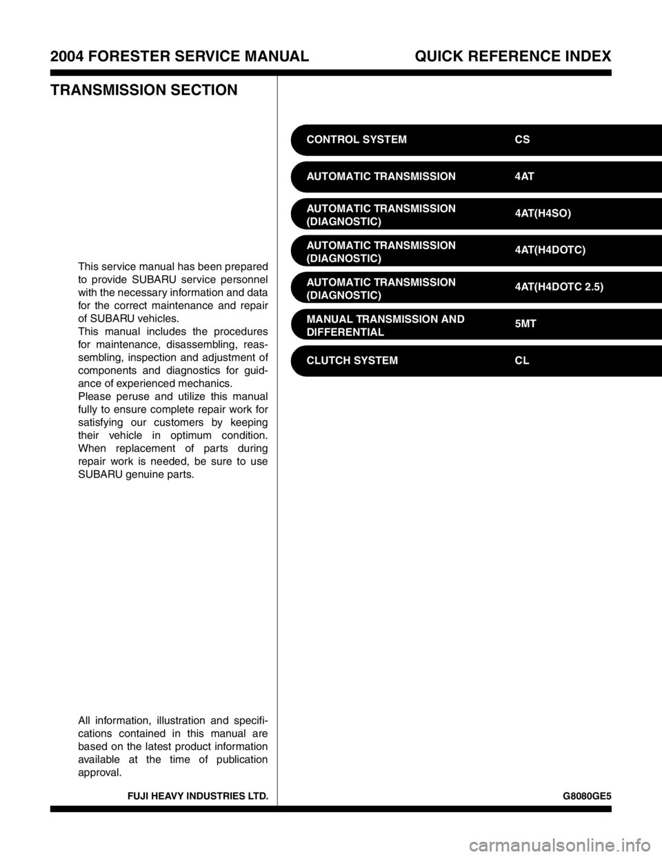
TRANSMISSION SECTION
This service manual has been prepared
to provide SUBARU service personnel
with the necessary information and data
for the correct maintenance and repair
of SUBARU vehicles.
This manual includes the procedures
for maintenance, disassembling, reas-
sembling, inspection and adjustment of
components and diagnostics for guid-
ance of experienced mechanics.
Please peruse and utilize this manual
fully to ensure complete repair work for
satisfying our customers by keeping
their vehicle in optimum condition.
When replacement of parts during
repair work is needed, be sure to use
SUBARU genuine parts.
All information, illustration and specifi-
cations contained in this manual are
based on the latest product information
available at the time of publication
approval.CONTROL SYSTEM CS
AUTOMATIC TRANSMISSION 4AT
AUTOMATIC TRANSMISSION
(DIAGNOSTIC)4AT(H4SO)
AUTOMATIC TRANSMISSION
(DIAGNOSTIC)4AT(H4DOTC)
AUTOMATIC TRANSMISSION
(DIAGNOSTIC)4AT(H4DOTC 2.5)
MANUAL TRANSMISSION AND
DIFFERENTIAL5MT
CLUTCH SYSTEM CL
Page 2312 of 2870

FUJI HEAVY INDUSTRIES LTD. G8080GE5
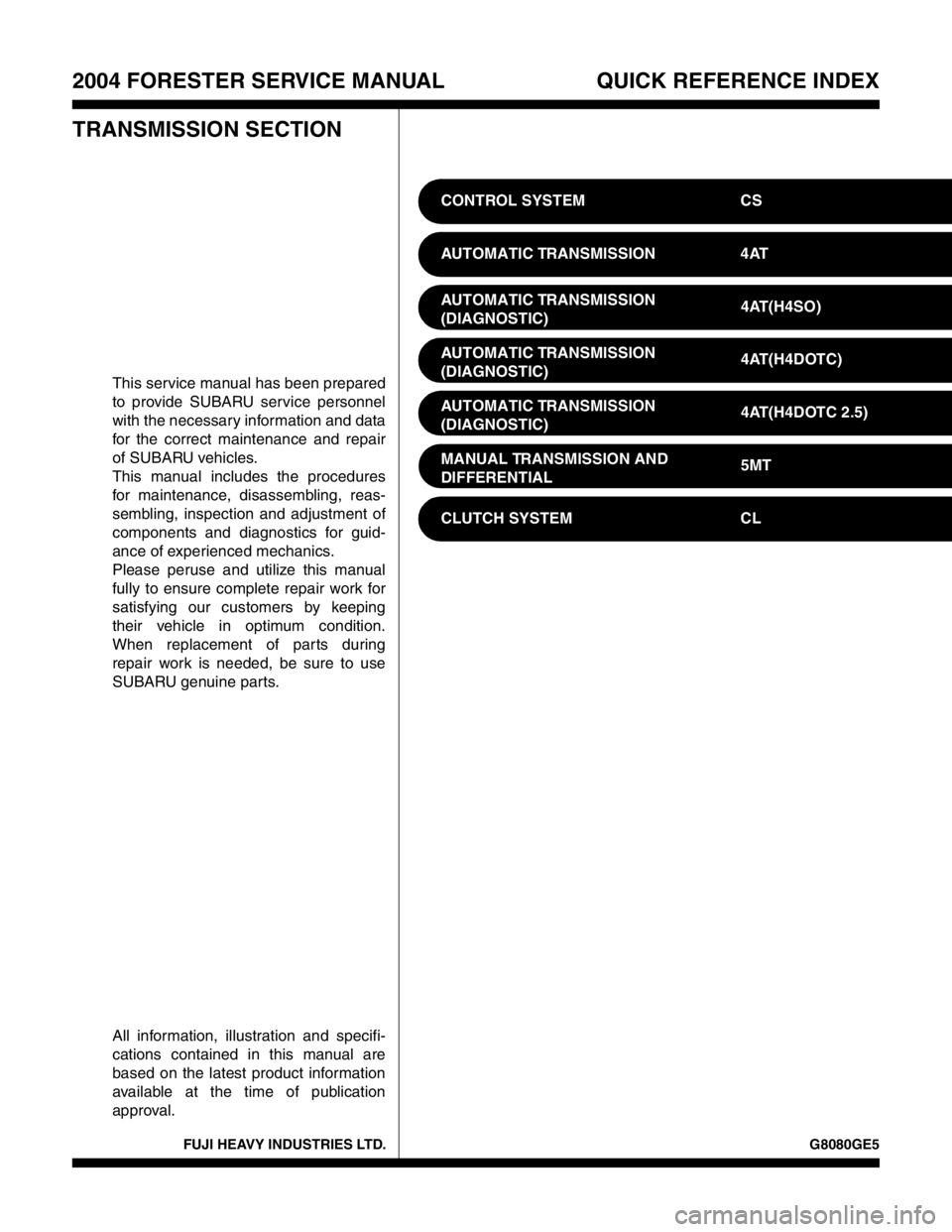
2004 FORESTER SERVICE MANUAL QUICK REFERENCE INDEX
TRANSMISSION SECTION
This service manual has been prepared
to provide SUBARU service personnel
with the necessary information and data
for the correct maintenance and repair
of SUBARU vehicles.
This manual includes the procedures
for maintenance, disassembling, reas-
sembling, inspection and adjustment of
components and diagnostics for guid-
ance of experienced mechanics.
Please peruse and utilize this manual
fully to ensure complete repair work for
satisfying our customers by keeping
their vehicle in optimum condition.
When replacement of parts during
repair work is needed, be sure to use
SUBARU genuine parts.
All information, illustration and specifi-
cations contained in this manual are
based on the latest product information
available at the time of publication
approval.CONTROL SYSTEM CS
AUTOMATIC TRANSMISSION 4AT
AUTOMATIC TRANSMISSION
(DIAGNOSTIC)4AT(H4SO)
AUTOMATIC TRANSMISSION
(DIAGNOSTIC)4AT(H4DOTC)
AUTOMATIC TRANSMISSION
(DIAGNOSTIC)4AT(H4DOTC 2.5)
MANUAL TRANSMISSION AND
DIFFERENTIAL5MT
CLUTCH SYSTEM CL
Page 2313 of 2870

AUTOMATIC TRANSMISSION
4AT
Page
1. General Description ....................................................................................2
2. Automatic Transmission Fluid ...................................................................30
3. Differential Gear Oil...................................................................................31
4. Road Test..................................................................................................32
5. Stall Test ...................................................................................................33
6. Time Lag Test ...........................................................................................35
7. Line Pressure Test ....................................................................................36
8. Transfer Clutch Pressure Test ..................................................................38
9. Automatic Transmission Assembly ...........................................................39
10. Transmission Mounting System ................................................................47
11. Extension Case Oil Seal ...........................................................................49
12. Differential Side Retainer Oil Seal.............................................................50
13. Inhibitor Switch ..........................................................................................51
14. Front Vehicle Speed Sensor .....................................................................55
15. Rear Vehicle Speed Sensor ......................................................................59
16. Torque Converter Turbine Speed Sensor .................................................60
17. Control Valve Body ...................................................................................61
18. Air Bleeding of Control Valve ....................................................................70
19.
Shift Solenoids, Duty Solenoids and ATF Temperature Sensor.........................71
20. Transfer Duty Solenoid and Valve Body ...................................................73
21. ATF Filter ..................................................................................................76
22. Transmission Control Module (TCM) ........................................................77
23. Dropping Resistor .....................................................................................78
24. ATF Cooler Pipe and Hose .......................................................................79
25. ATF Cooler (With Warmer Function).........................................................84
26. Air Breather Hose......................................................................................87
27. Oil Charger Pipe........................................................................................88
28. Torque Converter Clutch Assembly ..........................................................89
29. Extension Case .........................................................................................90
30. Transfer Clutch..........................................................................................92
31. Reduction Driven Gear..............................................................................97
32. Reduction Drive Gear................................................................................99
33. Parking Pawl ...........................................................................................101
34. Torque Converter Clutch Case ...............................................................102
35. Oil Pump Housing ...................................................................................105
36. Drive Pinion Shaft Assembly ...................................................................111
37. Front Differential......................................................................................117
38. AT Main Case .........................................................................................123
39. Transmission Control Device ..................................................................142
Page 2314 of 2870

4AT-2
AUTOMATIC TRANSMISSION
General Description
1. General Description
A: SPECIFICATION
1. TORQUE CONVERTER CLUTCH
2. OIL PUMP
3. TRANSMISSION CONTROL ELEMENT
4. TRANSMISSION GEAR RATIO5. PLANETARY GEAR AND PLATE
Model2.0 L
Non-
turbo2.5 L
Non-
turbo2.0 L
Tu r b o2.5 L
Tu r b o
Ty p eSymmetric, 3 element, single stage, 2 phase
torque converter
Stall torque
ratio2.0 —
2.21.9 —
2.11.85 —
2.152.05 —
2.35
Nominal
diameter246 mm (9.69 in)
Stall speed
(at sea level)2,000 —
2,500
rpm2,100 —
2,600
rpm2,600 —
3,300
rpm2,700 —
3,200
rpm
One-way
clutchSprague type one-way clutch
Type Pracoid constant-displacement pump
Driving method Driven by engine
Number of teethInner rotor 9
Outer rotor 10
Ty p e4-forward, 1-reverse, double-row plan-
etary gears
Multi-plate clutch 3 sets
Multi-plate brake 2 sets
One-way clutch
(sprague type)1 sets
Gear ratio
1st 2.785
2nd 1.545
3rd 1.000
4th 0.694
Rev 2.272
Model2.0 L Non-
turbo2.5 L Non-
turboTu r b o
Tooth num-
ber of front
sun gear33
Front pinion
number of
teeth21
Front inter-
nal gear
number of
teeth75
Tooth num-
ber of rear
sun gear42
Rear pinion
number of
teeth17
Tooth num-
ber of rear
internal gear75
Drive &
driven plate
number of
high clutch45
Drive &
driven plate
number of
low clutch467
Drive &
driven plate
number of
reverse
clutch2
Drive &
driven plate
number of 2-
4 brake34
Drive &
driven plate
number of
low &
reverse
brake467
Page 2315 of 2870

4AT-3
AUTOMATIC TRANSMISSION
General Description
6. SELECTOR POSITION
7. HYDRAULIC CONTROL AND LUBRICA-
TION
8. COOLING AND HARNESS9. TRANSFER
P (Park)Transmission in neutral, output member immov-
able, and engine start possible
R
(Reverse)Transmission in reverse
N (Neu-
tral)Transmission in neutral and engine start possi-
ble
D (Drive)Automatic gear change 1st
←
→ 2nd ←
→ 3rd ←
→
4th
3 (3rd)Automatic gear change 1st
←
→ 2nd ←
→ 3rd ←
4th
2 (2nd)Automatic gear change 1st
←
→ 2nd ← 3rd ←
4th
1 (1st)1st gear locked (Deceleration possible 1st ←
2nd ← 3rd ← 4th)
Control
methodWire cable type
Ty p eElectronic/hydraulic control
[Four forward speed
changes by electrical signals
of vehicle speed and accel-
erator (throttle) opening]
FluidDEXRON III type automatic
transmission fluid
Fluid capac-
ity2.0 L Non-
turbo model8.4 — 8.72 (8.9 — 9.2 US
qt, 7.4 — 7.7 Imp qt)
Except for
2.0 L Non-
turbo model9.3 — 9.62 (9.8 — 10.1 US
qt, 8.2 — 8.4 Imp qt)
Lubrication systemForced feed lubrication with
oil pump
OilAutomatic transmission fluid
(above mentioned)
Cooling SystemLiquid-cooled cooler incorpo-
rated in radiator
Inhibitor switch 12 poles
Transmission harness 20 poles
Model2.0 L Non-
turbo2.5 L Non-
turboTu r b o
Transfer
typeMulti-plate transfer (MPT)
Drive &
driven plate
number of
transfer
clutch456
Control
methodElectronic, hydraulic type
LubricantThe same Automatic transmission fluid used
in automatic transmission
Reduction
gear ratio1.000 (53/53)
Page 2316 of 2870

4AT-4
AUTOMATIC TRANSMISSION
General Description
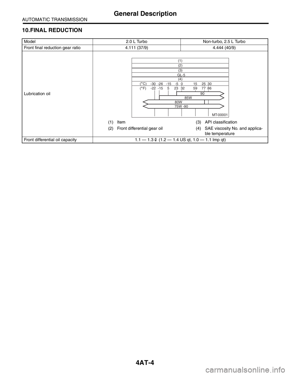
10.FINAL REDUCTION
Model 2.0 L Turbo Non-turbo, 2.5 L Turbo
Front final reduction gear ratio 4.111 (37/9) 4.444 (40/9)
Lubrication oil
(1) Item (3) API classification
(2) Front differential gear oil (4) SAE viscosity No. and applica-
ble temperature
Front differential oil capacity 1.1 — 1.32 (1.2 — 1.4 US qt, 1.0 — 1.1 Imp qt)
MT-00001
(1)
(4) GL-5(3) (2)
( C)( F)-30 -26 -15 15
90
85W
80W
75W -9025 30 -5 0-22-1523328659775