Page 2397 of 2870
4AT-84
AUTOMATIC TRANSMISSION
ATF Cooler (With Warmer Function)
25.ATF Cooler (With Warmer
Function)
A: REMOVAL
1) Drain engine coolant.
REPLACEMENT, Engine Coolant.>
2) Remove the air cleaner case.
6, REMOVAL, Air Cleaner Case.>
3) Remove the harness from bracket.
4) Disconnect the hose from pipe of transmission.
5) Disconnect the engine coolant inlet hose from
cylinder block and the engine coolant outlet hose
from upper side of engine.6) Remove the ATF Cooler (with warmer function)
from transmission body, and then disconnect the
hose located lower of ATF cooler (with warmer
function).
(A) Inlet pipe
(B) Outlet pipe
(A) Outlet hose
(B) Inlet hose
AT-01867
AT-01866(A)(B)
AT-02113
(A)
(B)
AT-01868
Page 2398 of 2870
4AT-85
AUTOMATIC TRANSMISSION
ATF Cooler (With Warmer Function)
B: INSTALLATION
1) Connect the hose to lower side of ATF cooler
(with warmer function), and then install the ATF
cooler (with warmer function) to transmission body.
NOTE:
Insert the tip of ATF cooler bracket into hole of
torque converter case.
Tightening torque:
T1: 21 N
⋅m (2.1 kgf-m, 15.5 ft-lb)
T2: 23 N
⋅m (2.3 kgf-m, 17.0 ft-lb)
T3: 33 N
⋅m (3.4 kgf-m, 24.3 ft-lb)
2) Connect the engine coolant inlet hose to cylinder
block and the engine coolant outlet hose to upper
side of engine.3) Connect the hose to pipe on transmission side.
4) Install the harness to bracket.
5) Install the air cleaner case.
REMOVAL, Air Cleaner Case.>
6) Fill with engine coolant.
REPLACEMENT, Engine Coolant.>
(A) Outlet hose
(B) Inlet hose
AT-01869
T2
T1T3
AT-02113
(A)
(B)
(A) Inlet pipe
(B) Outlet pipe
AT-01866(A)(B)
AT-01867
Page 2399 of 2870
4AT-86
AUTOMATIC TRANSMISSION
ATF Cooler (With Warmer Function)
C: DISASSEMBLY
1) Disconnect each connector from ATF cooler
(with warmer function).
2) Remove the ATF cooler (with warmer function)
from bracket.
D: ASSEMBLY
Assemble in the reverse order of disassembly.
CAUTION:
When connecting hose, be careful of its direc-
tion.
Tightening torque:
T1: 23 N
⋅m (2.3 kgf-m, 17.0 ft-lb)T2: 33 N
⋅m (3.4 kgf-m, 24.3 ft-lb)
E: INSPECTION
Check the ATF cooler (with warmer function) for
damage.
(A) ATF Outlet hose
(B) ATF Inlet hose
(C) Engine coolant inlet hose
(D) Engine coolant outlet hose
AT-02114
(A) (B)(C)
(D)
AT-02115
(A) ATF Inlet hose
(B) ATF Outlet hose
(C) Engine coolant outlet hose
(D) Engine coolant inlet hose
(A) ATF Inlet
(B) ATF Outlet
(C) Engine coolant outlet
(D) Engine coolant inlet
(E) Forward
AT-02116
T1
T2
(B)
(D) (C)
(A)
AT-02117
(D)(B)(A)
(C)
(E)
Page 2400 of 2870
4AT-87
AUTOMATIC TRANSMISSION
Air Breather Hose
26.Air Breather Hose
A: REMOVAL
1) Remove the air cleaner case. (Non-turbo mod-
el).
Case.>
2) Remove the intercooler. (Turbo model)
er.>
3) Disconnect the air breather hose.
Non-turbo model
Turbo model
B: INSTALLATION
1) Install the air breather hose.
Non-turbo model
Turbo model
2) Install the air cleaner case. (Non-turbo model).
Case.>
3) Install the intercooler. (Turbo model)
cooler.>
C: INSPECTION
Make sure the hose is not cracked or clogged.
(A) Air breather hose (Transmission case)
(B) Air breather hose (Oil pump housing)
(A) Air breather hose (Transmission case)
(B) Air breather hose (Oil pump housing)
AT-00099
AT-00098
(A) Air breather hose (Transmission case)
(B) Air breather hose (Oil pump housing)
(A) Air breather hose (Transmission case)
(B) Air breather hose (Oil pump housing)
AT-00099
AT-00098
Page 2401 of 2870
4AT-88
AUTOMATIC TRANSMISSION
Oil Charger Pipe
27.Oil Charger Pipe
A: REMOVAL
1) Remove the air cleaner case. (Non-turbo mod-
el).
Case.>
2) Remove the intercooler. (Turbo model)
er.>
3) Remove the ATF charger pipe, and then remove
the O-ring from flange side.
Model without ATF warmer
Model with ATF warmer
B: INSTALLATION
1) Install the ATF charger pipe with a new O-ring.
Tightening torque:
41 N
⋅m (4.2 kgf-m, 30.4 ft-lb)
Model without ATF warmer
Model with ATF warmer
2) Install the air cleaner case. (Non-turbo model).
Case.>
3) Install the intercooler. (Turbo model)
cooler.>
C: INSPECTION
Make sure the ATF charger pipe is not deformed or
damaged.
(A) ATF level gauge
(B) ATF charger pipe
(A) ATF level gauge
(B) ATF charger pipe
AT-00808
(A)
(B)
AT-01872
(B)
(A)
(A) ATF level gauge
(B) ATF charger pipe
(A) ATF level gauge
(B) ATF charger pipe
AT-00808
(A)
(B)
AT-01872
(B)
(A)
Page 2402 of 2870

4AT-89
AUTOMATIC TRANSMISSION
Torque Converter Clutch Assembly
28.Torque Converter Clutch As-
sembly
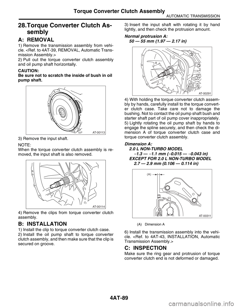
A: REMOVAL
1) Remove the transmission assembly from vehi-
cle.
mission Assembly.>
2) Pull out the torque converter clutch assembly
and oil pump shaft horizontally.
CAUTION:
Be sure not to scratch the inside of bush in oil
pump shaft.
3) Remove the input shaft.
NOTE:
When the torque converter clutch assembly is re-
moved, the input shaft is also removed.
4) Remove the clips from torque converter clutch
assembly.
B: INSTALLATION
1) Install the clip to torque converter clutch case.
2) Install the oil pump shaft to torque converter
clutch assembly, and then make sure that the clip is
secured on groove.3) Insert the input shaft with rotating it by hand
lightly, and then check the protrusion amount.
Normal protrusion A:
50 — 55 mm (1.97 — 2.17 in)
4) With holding the torque converter clutch assem-
bly by hands, carefully install to the torque convert-
er clutch case. Take care not to damage the
bushing. Not to contact the oil pump shaft bush and
starter shaft part of oil pump cover inappropriately.
5) Lightly rotating the oil pump shaft by hands to
engage the spline securely, and then check the di-
mension A of torque converter clutch case and
torque converter clutch assembly.
Dimension A:
2.0 L NON-TURBO MODEL
−1.3 — −1.1 mm (−0.015 — −0.043 in)
EXCEPT FOR 2.0 L NON-TURBO MODEL
2.7 — 2.9 mm (0.106 — 0.114 in)
6) Install the transmission assembly into the vehi-
cle.
Transmission Assembly.>
C: INSPECTION
Make sure the ring gear and protrusion of torque
converter clutch end is not deformed or damaged.
AT-00113
AT-00114
(A) Dimension A
AT-00291
A
AT-00311
(A)
Page 2403 of 2870
4AT-90
AUTOMATIC TRANSMISSION
Extension Case
29.Extension Case
A: REMOVAL
1) Remove the transmission assembly.
sion Assembly.>
2) Remove the rear vehicle speed sensor.
Non-turbo model
Turbo model
3) Separate the transmission case and extension
case part.
B: INSTALLATION
1) Apply the vaseline to selected thrust needle
bearing and attach it to the end surface of reduction
driven gear.
Transfer Clutch.>
NOTE:
Install the thrust needle bearing in correct direction.
2) Install a new gasket.
3) Install the extension case to transmission case.
4) Tighten bolts to secure the extension case.
Tightening torque:
25 N
⋅m (2.5 kgf-m, 18.1 ft-lb)
5) Install the rear vehicle speed sensor.
Tightening torque:
7 N
⋅m (0.7 kgf-m, 5.1 ft-lb)
Non-turbo model
(A) Rear vehicle speed sensor
(B) Front vehicle speed sensor
(A) Rear vehicle speed sensor
AT-00116
(B)
(A)
AT-01338
(A)
AT-00118
(A) Rear vehicle speed sensor
(B) Front vehicle speed sensor
AT-00118
AT-00116
(B)
(A)
Page 2404 of 2870

4AT-91
AUTOMATIC TRANSMISSION
Extension Case
Turbo model
6) Install the transmission assembly.
Transmission Assembly.>
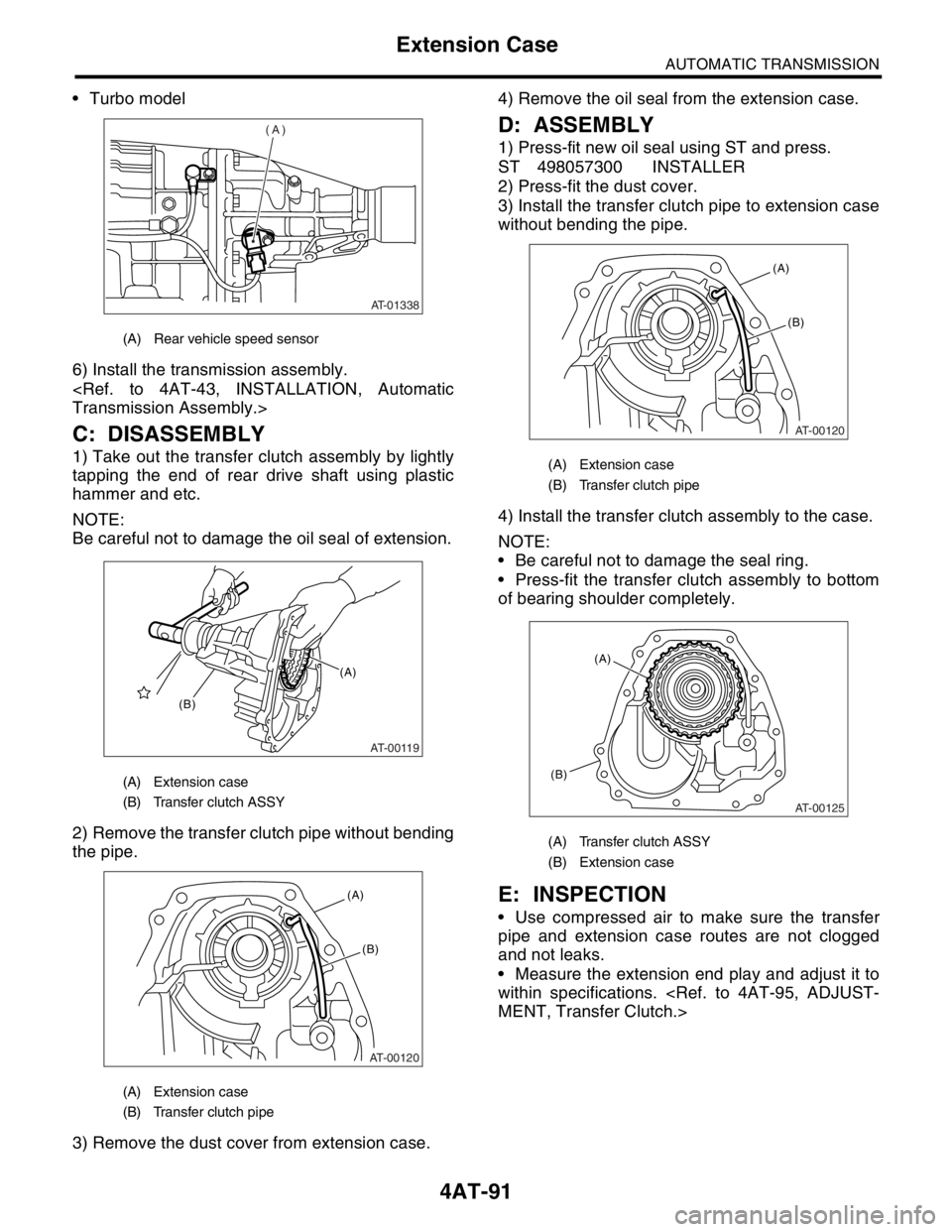
C: DISASSEMBLY
1) Take out the transfer clutch assembly by lightly
tapping the end of rear drive shaft using plastic
hammer and etc.
NOTE:
Be careful not to damage the oil seal of extension.
2) Remove the transfer clutch pipe without bending
the pipe.
3) Remove the dust cover from extension case.4) Remove the oil seal from the extension case.
D: ASSEMBLY
1) Press-fit new oil seal using ST and press.
ST 498057300 INSTALLER
2) Press-fit the dust cover.
3) Install the transfer clutch pipe to extension case
without bending the pipe.
4) Install the transfer clutch assembly to the case.
NOTE:
Be careful not to damage the seal ring.
Press-fit the transfer clutch assembly to bottom
of bearing shoulder completely.
E: INSPECTION
Use compressed air to make sure the transfer
pipe and extension case routes are not clogged
and not leaks.
Measure the extension end play and adjust it to
within specifications.
MENT, Transfer Clutch.>
(A) Rear vehicle speed sensor
(A) Extension case
(B) Transfer clutch ASSY
(A) Extension case
(B) Transfer clutch pipe
AT-01338
(A)
AT-00119
(A)
(B)
AT-00120
(A)
(B)
(A) Extension case
(B) Transfer clutch pipe
(A) Transfer clutch ASSY
(B) Extension case
AT-00120
(A)
(B)
AT-00125
(A)
(B)