Page 410 of 2870
SE-6
SEAT
Front Seat
2. Front Seat
A: REMOVAL
1) Disconnect the ground cable from battery.
WARNING:
The airbag system is fitted with a backup power
source. If the airbag system is serviced within 20
seconds after the ground cable is disconnected,
it may inflate.
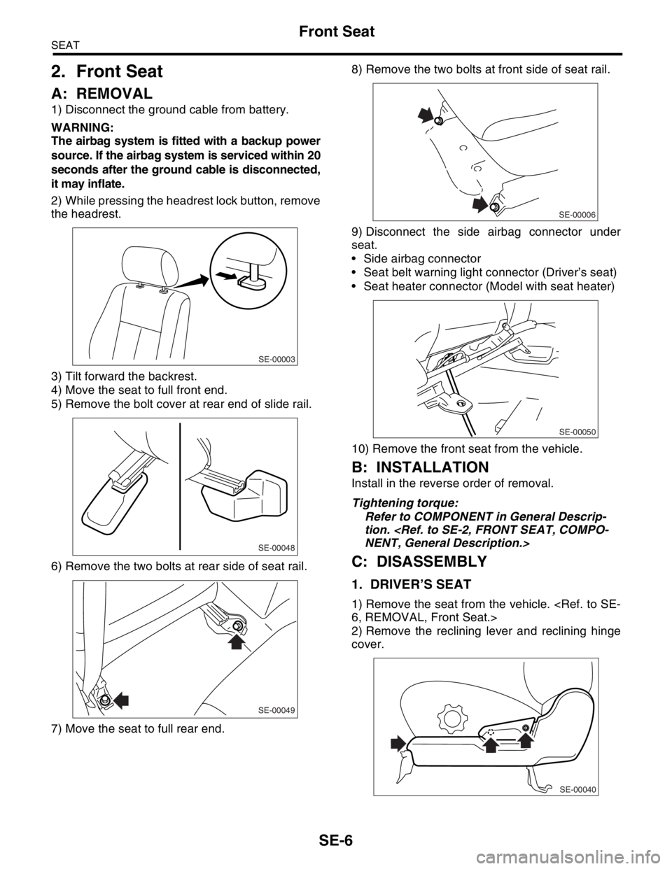
2) While pressing the headrest lock button, remove
the headrest.
3) Tilt forward the backrest.
4) Move the seat to full front end.
5) Remove the bolt cover at rear end of slide rail.
6) Remove the two bolts at rear side of seat rail.
7) Move the seat to full rear end.8) Remove the two bolts at front side of seat rail.
9) Disconnect the side airbag connector under
seat.
Side airbag connector
Seat belt warning light connector (Driver’s seat)
Seat heater connector (Model with seat heater)
10) Remove the front seat from the vehicle.
B: INSTALLATION
Install in the reverse order of removal.
Tightening torque:
Refer to COMPONENT in General Descrip-
tion.
NENT, General Description.>
C: DISASSEMBLY
1. DRIVER’S SEAT
1) Remove the seat from the vehicle.
6, REMOVAL, Front Seat.>
2) Remove the reclining lever and reclining hinge
cover.
SE-00003
SE-00048
SE-00049
SE-00006
SE-00050
SE-00040
Page 412 of 2870
SE-8
SEAT
Front Seat
9) Remove the hog rings (A) which secure the
backrest cover and backrest pad.
10) Remove the headrest bushes.
NOTE:
Push the headrest bushes to outside of seat from
inside, and then remove them.
11) Pull out the backrest frame.
12) Remove the hog rings (A) at bottom of seat
back.
13) Remove the hog rings (A) at front of seat back,
and then remove the seat back cover from seat
back.14) Remove the connecting wire (A), and then
loosen the bolts and nuts to remove slide rail.
15) Remove the inner belt.
16) Remove the hook (A), and then remove the
seat cushion frame.
SE-00242
(A)
SE-00243
SE-00244(A)
SE-00378
(A)
SE-00295
(A)
SE-00297
SE-00268
(A)
Page 415 of 2870
SE-11
SEAT
Front Seat
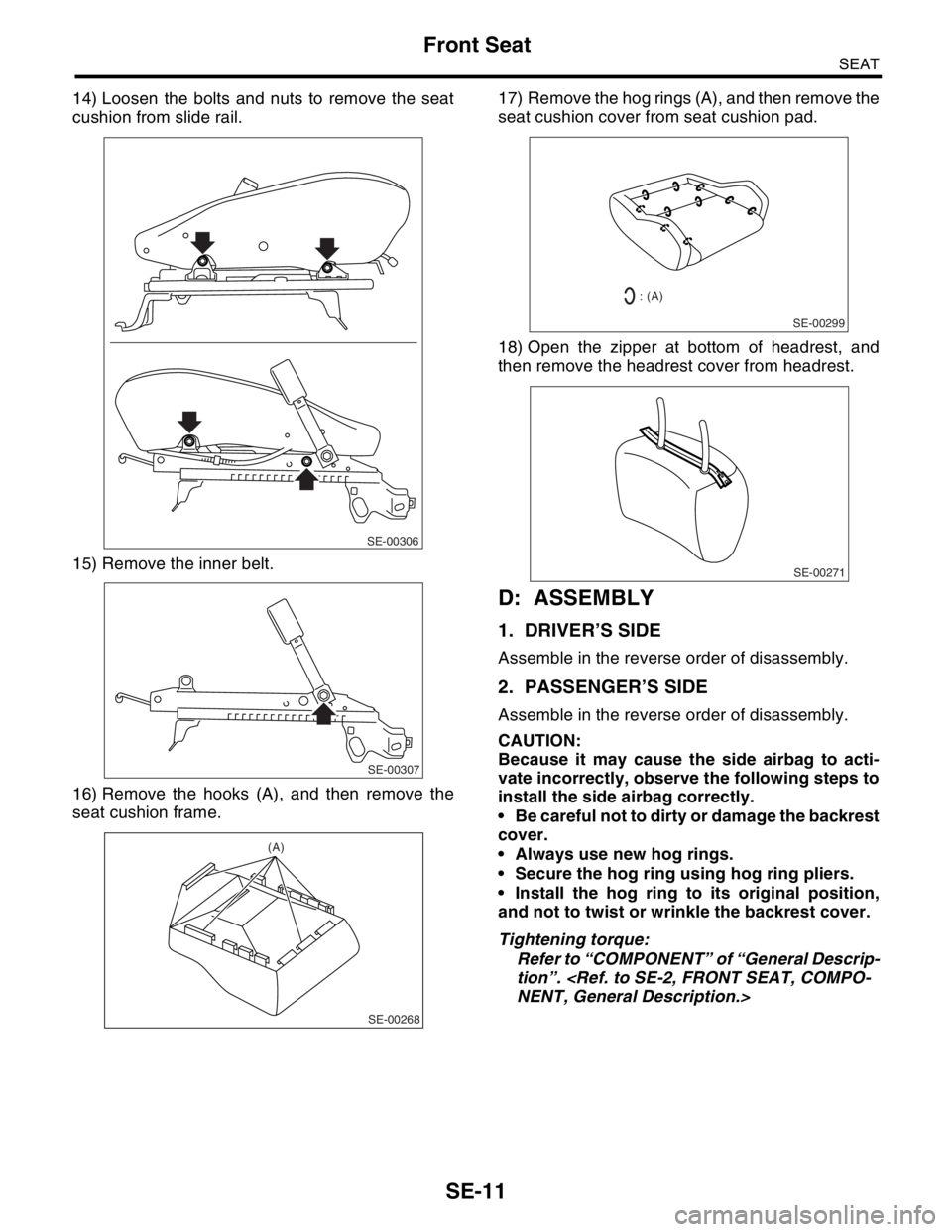
14) Loosen the bolts and nuts to remove the seat
cushion from slide rail.
15) Remove the inner belt.
16) Remove the hooks (A), and then remove the
seat cushion frame.17) Remove the hog rings (A), and then remove the
seat cushion cover from seat cushion pad.
18) Open the zipper at bottom of headrest, and
then remove the headrest cover from headrest.
D: ASSEMBLY
1. DRIVER’S SIDE
Assemble in the reverse order of disassembly.
2. PASSENGER’S SIDE
Assemble in the reverse order of disassembly.
CAUTION:
Because it may cause the side airbag to acti-
vate incorrectly, observe the following steps to
install the side airbag correctly.
Be careful not to dirty or damage the backrest
cover.
Always use new hog rings.
Secure the hog ring using hog ring pliers.
Install the hog ring to its original position,
and not to twist or wrinkle the backrest cover.
Tightening torque:
Refer to “COMPONENT” of “General Descrip-
tion”.
NENT, General Description.>
SE-00306
SE-00307
SE-00268
(A)
SE-00299
: (A)
SE-00271
Page 419 of 2870
FUJI HEAVY INDUSTRIES LTD. G8080GE7
2004 FORESTER SERVICE MANUAL QUICK REFERENCE INDEX
BODY SECTION
This service manual has been prepared
to provide SUBARU service personnel
with the necessary information and data
for the correct maintenance and repair
of SUBARU vehicles.
This manual includes the procedures
for maintenance, disassembling, reas-
sembling, inspection and adjustment of
components and diagnostics for guid-
ance of experienced mechanics.
Please peruse and utilize this manual
fully to ensure complete repair work for
satisfying our customers by keeping
their vehicle in optimum condition.
When replacement of parts during
repair work is needed, be sure to use
SUBARU genuine parts.
All information, illustration and specifi-
cations contained in this manual are
based on the latest product information
available at the time of publication
approval.HVAC SYSTEM
(HEATER, VENTILATOR AND A/C)AC
HVAC SYSTEM (AUTO A/C)
(DIAGNOSTIC)AC
AIRBAG SYSTEM AB
AIRBAG SYSTEM (DIAGNOSTIC) AB
SEAT BELT SYSTEM SB
LIGHTING SYSTEM LI
WIPER AND WASHER SYSTEM WW
ENTERTAINMENT ET
COMMUNICATION SYSTEM COM
GLASS/WINDOW/MIRROR GW
BODY STRUCTURE BS
INSTRUMENTATION/DRIVER INFO IDI
SEAT SE
SECURITY AND LOCK SL
SUNROOF/T-TOP/CONVERTIBLE TOP
(SUNROOF)SR
EXTERIOR/INTERIOR TRIM EI
EXTERIOR BODY PANEL EB
Page 463 of 2870
FUJI HEAVY INDUSTRIES LTD. G8080GE7
2004 FORESTER SERVICE MANUAL QUICK REFERENCE INDEX
BODY SECTION
This service manual has been prepared
to provide SUBARU service personnel
with the necessary information and data
for the correct maintenance and repair
of SUBARU vehicles.
This manual includes the procedures
for maintenance, disassembling, reas-
sembling, inspection and adjustment of
components and diagnostics for guid-
ance of experienced mechanics.
Please peruse and utilize this manual
fully to ensure complete repair work for
satisfying our customers by keeping
their vehicle in optimum condition.
When replacement of parts during
repair work is needed, be sure to use
SUBARU genuine parts.
All information, illustration and specifi-
cations contained in this manual are
based on the latest product information
available at the time of publication
approval.HVAC SYSTEM
(HEATER, VENTILATOR AND A/C)AC
HVAC SYSTEM (AUTO A/C)
(DIAGNOSTIC)AC
AIRBAG SYSTEM AB
AIRBAG SYSTEM (DIAGNOSTIC) AB
SEAT BELT SYSTEM SB
LIGHTING SYSTEM LI
WIPER AND WASHER SYSTEM WW
ENTERTAINMENT ET
COMMUNICATION SYSTEM COM
GLASS/WINDOW/MIRROR GW
BODY STRUCTURE BS
INSTRUMENTATION/DRIVER INFO IDI
SEAT SE
SECURITY AND LOCK SL
SUNROOF/T-TOP/CONVERTIBLE TOP
(SUNROOF)SR
EXTERIOR/INTERIOR TRIM EI
EXTERIOR BODY PANEL EB
Page 475 of 2870
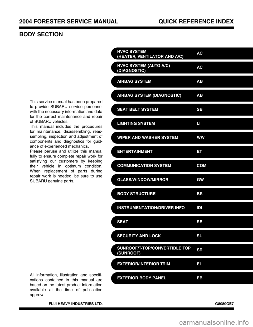
FUJI HEAVY INDUSTRIES LTD. G8080GE7
2004 FORESTER SERVICE MANUAL QUICK REFERENCE INDEX
BODY SECTION
This service manual has been prepared
to provide SUBARU service personnel
with the necessary information and data
for the correct maintenance and repair
of SUBARU vehicles.
This manual includes the procedures
for maintenance, disassembling, reas-
sembling, inspection and adjustment of
components and diagnostics for guid-
ance of experienced mechanics.
Please peruse and utilize this manual
fully to ensure complete repair work for
satisfying our customers by keeping
their vehicle in optimum condition.
When replacement of parts during
repair work is needed, be sure to use
SUBARU genuine parts.
All information, illustration and specifi-
cations contained in this manual are
based on the latest product information
available at the time of publication
approval.HVAC SYSTEM
(HEATER, VENTILATOR AND A/C)AC
HVAC SYSTEM (AUTO A/C)
(DIAGNOSTIC)AC
AIRBAG SYSTEM AB
AIRBAG SYSTEM (DIAGNOSTIC) AB
SEAT BELT SYSTEM SB
LIGHTING SYSTEM LI
WIPER AND WASHER SYSTEM WW
ENTERTAINMENT ET
COMMUNICATION SYSTEM COM
GLASS/WINDOW/MIRROR GW
BODY STRUCTURE BS
INSTRUMENTATION/DRIVER INFO IDI
SEAT SE
SECURITY AND LOCK SL
SUNROOF/T-TOP/CONVERTIBLE TOP
(SUNROOF)SR
EXTERIOR/INTERIOR TRIM EI
EXTERIOR BODY PANEL EB
Page 519 of 2870
EI-43
EXTERIOR/INTERIOR TRIM
Upper Inner Trim
17.Upper Inner Trim
A: REMOVAL
1) Remove the lower inner trim.
MOVAL, Lower Inner Trim.>
2) Remove the front molding (A).
3) Remove the front pillar upper trim (B).
4) Detach the front seat belt shoulder anchor, then
remove the center pillar upper trim (C).
B: INSTALLATION
Install in the reverse order of removal.
CAUTION:
Be sure to securely hook pawls of inner trim
panel to body flange.
NOTE:
When installing the center pillar upper trim and front
pillar upper trim, be sure to set the front molding as
shown in the figure.
(D) Clip
(A) Outside
(B) Inside
(C) Molding
(D) Weather strip
(E) Trim
(F) Body
EI-00105
(A)
(B)(C)
: (D)
EI-00106
(A)
(C)(B)
(E)
(F) (D)
Page 521 of 2870
EI-45
EXTERIOR/INTERIOR TRIM
Rear Quarter Trim
19.Rear Quarter Trim
A: REMOVAL
1) Remove the rear seat.
AL, Rear Seat.>
2) Remove the side sill rear cover.
3) Remove the rear rail trim (A).
4) Remove the strut cap.
5) Remove the shoulder anchor of rear seat belt.
6) Loosen the screws and clips to remove rear
quarter upper trim (B).
7) Remove the rear skirt trim (C).
8) Loosen the screws and clips to remove rear
quarter lower trim (D).
B: INSTALLATION
Install in the reverse order of removal.
CAUTION:
Be sure to securely hook pawls of inner trim
panel to body flange.
NOTE:
When installing the rear quarter upper trim, be sure
to set the rear molding as shown in the figure.
(E) Clip
(F) Hook
EI-00073
(D)(A)
(B)
(C)
: (E): (F)
(A) Outside
(B) Inside
(C) Molding
(D) Weather strip
(E) Trim
(F) Body
EI-00106
(A)
(C)(B)
(E)
(F) (D)