Page 1538 of 2870
ME(H4DOTC)-80
MECHANICAL
Cylinder Head Assembly
(9) Recheck the contact condition between
valve and valve seat after replacing the valve
guide.
4. INTAKE AND EXHAUST VALVE
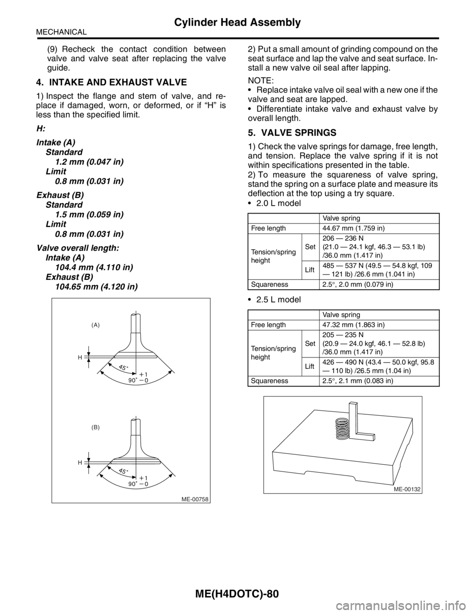
1) Inspect the flange and stem of valve, and re-
place if damaged, worn, or deformed, or if “H” is
less than the specified limit.
H:
Intake (A)
Standard
1.2 mm (0.047 in)
Limit
0.8 mm (0.031 in)
Exhaust (B)
Standard
1.5 mm (0.059 in)
Limit
0.8 mm (0.031 in)
Valve overall length:
Intake (A)
104.4 mm (4.110 in)
Exhaust (B)
104.65 mm (4.120 in)2) Put a small amount of grinding compound on the
seat surface and lap the valve and seat surface. In-
stall a new valve oil seal after lapping.
NOTE:
Replace intake valve oil seal with a new one if the
valve and seat are lapped.
Differentiate intake valve and exhaust valve by
overall length.
5. VALVE SPRINGS
1) Check the valve springs for damage, free length,
and tension. Replace the valve spring if it is not
within specifications presented in the table.
2) To measure the squareness of valve spring,
stand the spring on a surface plate and measure its
deflection at the top using a try square.
2.0 L model
2.5 L model
ME-00758
H
H
(B) (A)
Valve spring
Free length 44.67 mm (1.759 in)
Tension/spring
heightSet206 — 236 N
(21.0 — 24.1 kgf, 46.3 — 53.1 lb)
/36.0 mm (1.417 in)
Lift485 — 537 N (49.5 — 54.8 kgf, 109
— 121 lb) /26.6 mm (1.041 in)
Squareness 2.5°, 2.0 mm (0.079 in)
Valve spring
Free length 47.32 mm (1.863 in)
Tension/spring
heightSet205 — 235 N
(20.9 — 24.0 kgf, 46.1 — 52.8 lb)
/36.0 mm (1.417 in)
Lift426 — 490 N (43.4 — 50.0 kgf, 95.8
— 110 lb) /26.5 mm (1.04 in)
Squareness 2.5°, 2.1 mm (0.083 in)
ME-00132
Page 1539 of 2870
ME(H4DOTC)-81
MECHANICAL
Cylinder Head Assembly
6. INTAKE AND EXHAUST VALVE OIL
SEAL
1) Replace the oil seal with a new one in the follow-
ing condition, Refer to procedure 2) for replace-
ment procedure.
Lip portion is damaged.
Spring is out of place.
Valve and valve seat are reconditioned.
Valve guide is replaced.
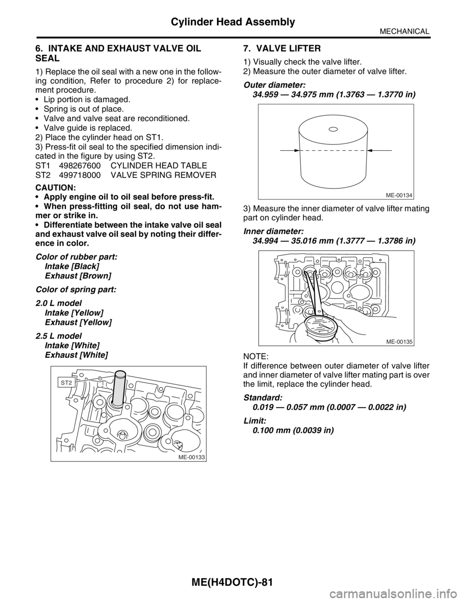
2) Place the cylinder head on ST1.
3) Press-fit oil seal to the specified dimension indi-
cated in the figure by using ST2.
ST1 498267600 CYLINDER HEAD TABLE
ST2 499718000 VALVE SPRING REMOVER
CAUTION:
Apply engine oil to oil seal before press-fit.
When press-fitting oil seal, do not use ham-
mer or strike in.
Differentiate between the intake valve oil seal
and exhaust valve oil seal by noting their differ-
ence in color.
Color of rubber part:
Intake [Black]
Exhaust [Brown]
Color of spring part:
2.0 L model
Intake [Yellow]
Exhaust [Yellow]
2.5 L model
Intake [White]
Exhaust [White]
7. VALVE LIFTER
1) Visually check the valve lifter.
2) Measure the outer diameter of valve lifter.
Outer diameter:
34.959 — 34.975 mm (1.3763 — 1.3770 in)
3) Measure the inner diameter of valve lifter mating
part on cylinder head.
Inner diameter:
34.994 — 35.016 mm (1.3777 — 1.3786 in)
NOTE:
If difference between outer diameter of valve lifter
and inner diameter of valve lifter mating part is over
the limit, replace the cylinder head.
Standard:
0.019 — 0.057 mm (0.0007 — 0.0022 in)
Limit:
0.100 mm (0.0039 in)
ME-00133
ST2
ME-00134
ME-00135
Page 1565 of 2870
ME(H4DOTC)-105
MECHANICAL
Cylinder Block
D: ASSEMBLY
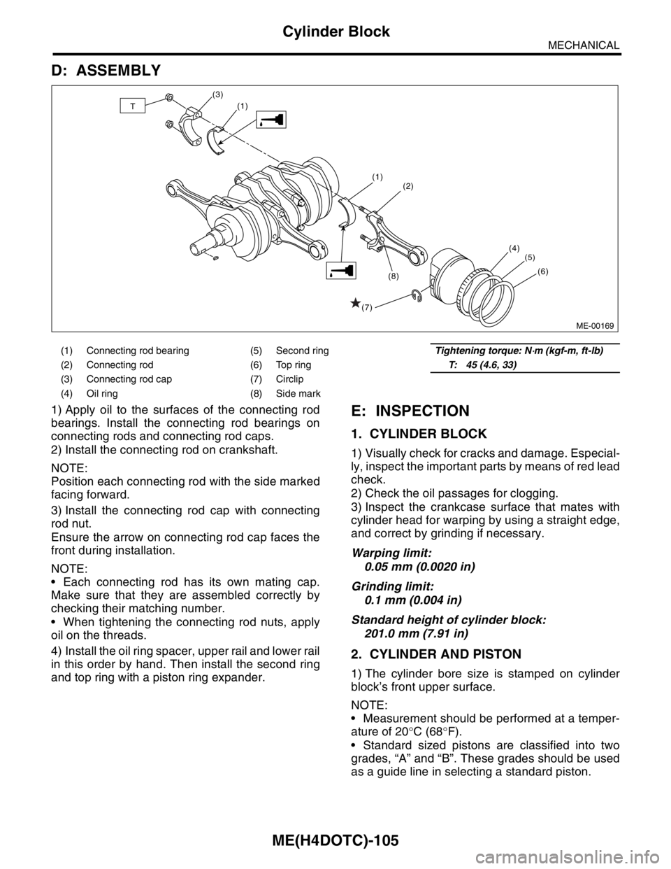
1) Apply oil to the surfaces of the connecting rod
bearings. Install the connecting rod bearings on
connecting rods and connecting rod caps.
2) Install the connecting rod on crankshaft.
NOTE:
Position each connecting rod with the side marked
facing forward.
3) Install the connecting rod cap with connecting
rod nut.
Ensure the arrow on connecting rod cap faces the
front during installation.
NOTE:
Each connecting rod has its own mating cap.
Make sure that they are assembled correctly by
checking their matching number.
When tightening the connecting rod nuts, apply
oil on the threads.
4) Install the oil ring spacer, upper rail and lower rail
in this order by hand. Then install the second ring
and top ring with a piston ring expander.E: INSPECTION
1. CYLINDER BLOCK
1) Visually check for cracks and damage. Especial-
ly, inspect the important parts by means of red lead
check.
2) Check the oil passages for clogging.
3) Inspect the crankcase surface that mates with
cylinder head for warping by using a straight edge,
and correct by grinding if necessary.
Warping limit:
0.05 mm (0.0020 in)
Grinding limit:
0.1 mm (0.004 in)
Standard height of cylinder block:
201.0 mm (7.91 in)
2. CYLINDER AND PISTON
1) The cylinder bore size is stamped on cylinder
block’s front upper surface.
NOTE:
Measurement should be performed at a temper-
ature of 20°C (68°F).
Standard sized pistons are classified into two
grades, “A” and “B”. These grades should be used
as a guide line in selecting a standard piston.
(1) Connecting rod bearing (5) Second ringTightening torque: N⋅m (kgf-m, ft-lb)
(2) Connecting rod (6) Top ringT: 45 (4.6, 33)
(3) Connecting rod cap (7) Circlip
(4) Oil ring (8) Side mark
ME-00169
(2)
(4)
(5)
(6)
(1)
(1)
(7)(8) (3)T
Page 1568 of 2870
ME(H4DOTC)-108
MECHANICAL
Cylinder Block
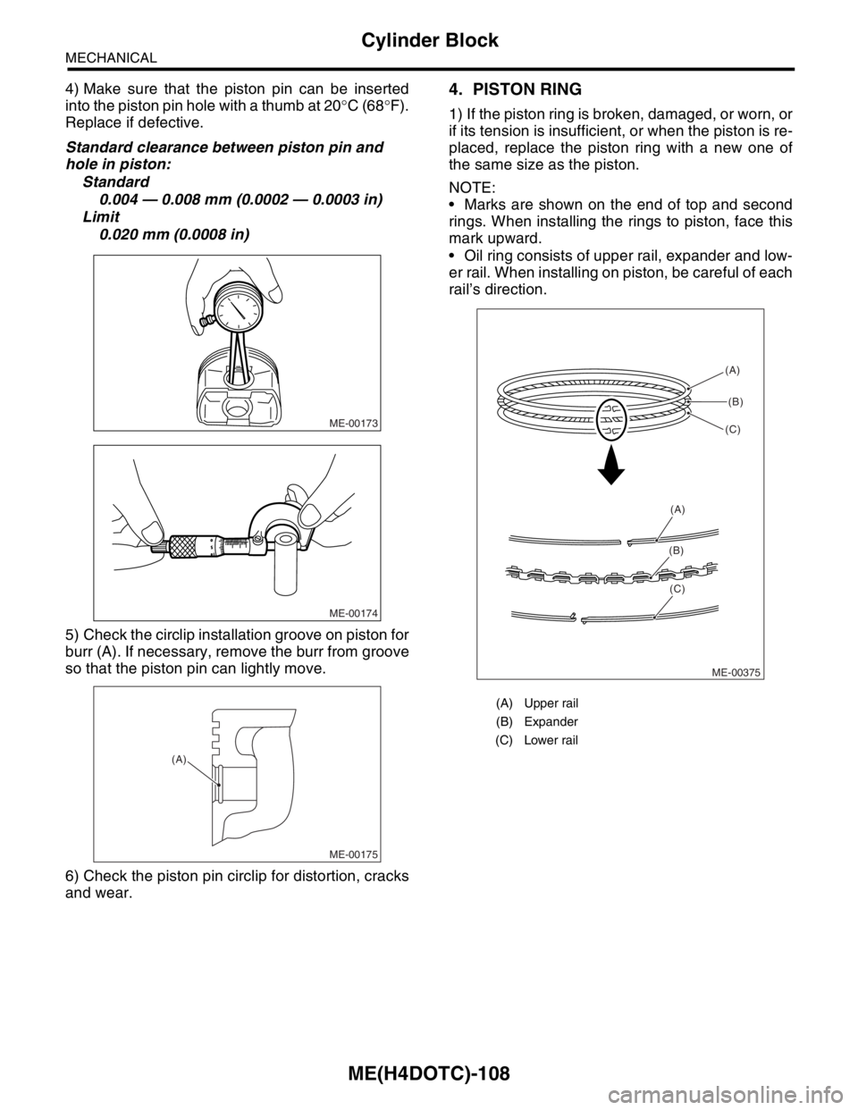
4) Make sure that the piston pin can be inserted
into the piston pin hole with a thumb at 20°C (68°F).
Replace if defective.
Standard clearance between piston pin and
hole in piston:
Standard
0.004 — 0.008 mm (0.0002 — 0.0003 in)
Limit
0.020 mm (0.0008 in)
5) Check the circlip installation groove on piston for
burr (A). If necessary, remove the burr from groove
so that the piston pin can lightly move.
6) Check the piston pin circlip for distortion, cracks
and wear.4. PISTON RING
1) If the piston ring is broken, damaged, or worn, or
if its tension is insufficient, or when the piston is re-
placed, replace the piston ring with a new one of
the same size as the piston.
NOTE:
Marks are shown on the end of top and second
rings. When installing the rings to piston, face this
mark upward.
Oil ring consists of upper rail, expander and low-
er rail. When installing on piston, be careful of each
rail’s direction.
ME-00173
ME-00174
ME-00175
(A)
(A) Upper rail
(B) Expander
(C) Lower rail
ME-00375(A)
(B)
(C)
(A)
(B)
(C)
Page 1569 of 2870
ME(H4DOTC)-109
MECHANICAL
Cylinder Block
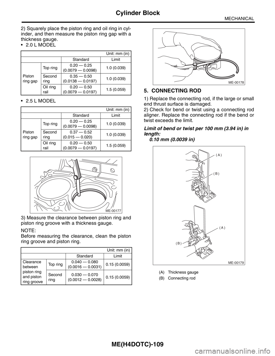
2) Squarely place the piston ring and oil ring in cyl-
inder, and then measure the piston ring gap with a
thickness gauge.
2.0 L MODEL
2.5 L MODEL
3) Measure the clearance between piston ring and
piston ring groove with a thickness gauge.
NOTE:
Before measuring the clearance, clean the piston
ring groove and piston ring.
5. CONNECTING ROD
1) Replace the connecting rod, if the large or small
end thrust surface is damaged.
2) Check for bend or twist using a connecting rod
aligner. Replace the connecting rod if the bend or
twist exceeds the limit.
Limit of bend or twist per 100 mm (3.94 in) in
length:
0.10 mm (0.0039 in)
Unit: mm (in)
Standard Limit
Piston
ring gapTop ring0.20 — 0.25
(0.0079 — 0.0098)1.0 (0.039)
Second
ring0.35 — 0.50
(0.0138 — 0.0197)1.0 (0.039)
Oil ring
rail0.20 — 0.50
(0.0079 — 0.0197)1.5 (0.059)
Unit: mm (in)
Standard Limit
Piston
ring gapTop ring0.20 — 0.25
(0.0079 — 0.0098)1.0 (0.039)
Second
ring0.37 — 0.52
(0.015 — 0.020)1.0 (0.039)
Oil ring
rail0.20 — 0.50
(0.0079 — 0.0197)1.5 (0.059)
Unit: mm (in)
Standard Limit
Clearance
between
piston ring
and piston
ring grooveTop ring0.040 — 0.080
(0.0016 — 0.0031)0.15 (0.0059)
Second
ring0.030 — 0.070
(0.0012 — 0.0028)0.15 (0.0059)
ME-00177
(A) Thickness gauge
(B) Connecting rod
ME-00178
(A)
(A) (B)
(B)
ME-00179
Page 1571 of 2870
ME(H4DOTC)-111
MECHANICAL
Cylinder Block
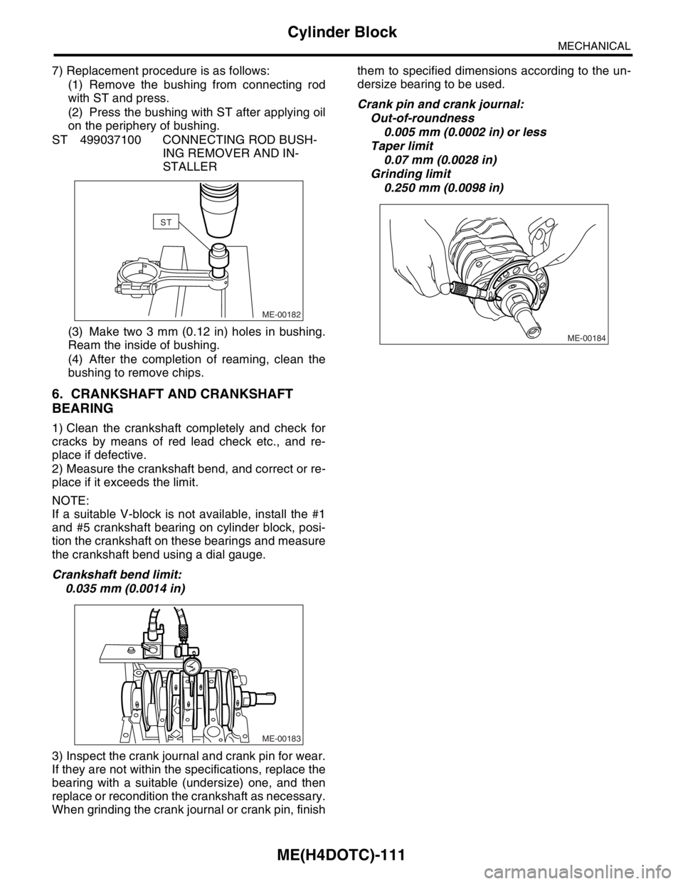
7) Replacement procedure is as follows:
(1) Remove the bushing from connecting rod
with ST and press.
(2) Press the bushing with ST after applying oil
on the periphery of bushing.
ST 499037100 CONNECTING ROD BUSH-
ING REMOVER AND IN-
STALLER
(3) Make two 3 mm (0.12 in) holes in bushing.
Ream the inside of bushing.
(4) After the completion of reaming, clean the
bushing to remove chips.
6. CRANKSHAFT AND CRANKSHAFT
BEARING
1) Clean the crankshaft completely and check for
cracks by means of red lead check etc., and re-
place if defective.
2) Measure the crankshaft bend, and correct or re-
place if it exceeds the limit.
NOTE:
If a suitable V-block is not available, install the #1
and #5 crankshaft bearing on cylinder block, posi-
tion the crankshaft on these bearings and measure
the crankshaft bend using a dial gauge.
Crankshaft bend limit:
0.035 mm (0.0014 in)
3) Inspect the crank journal and crank pin for wear.
If they are not within the specifications, replace the
bearing with a suitable (undersize) one, and then
replace or recondition the crankshaft as necessary.
When grinding the crank journal or crank pin, finishthem to specified dimensions according to the un-
dersize bearing to be used.
Crank pin and crank journal:
Out-of-roundness
0.005 mm (0.0002 in) or less
Taper limit
0.07 mm (0.0028 in)
Grinding limit
0.250 mm (0.0098 in)
ME-00182
ST
ME-00183
ME-00184
Page 1622 of 2870

IG(H4DOTC)-6
IGNITION
Spark Plug
5) Disconnect the connector from ignition coil.
6) Remove the ignition coil.
7) Remove the spark plugs with the spark plug
sockets.
B: INSTALLATION
1. RH SIDE
Install in the reverse order of removal.
Tightening torque (Spark plug):
21 N
⋅m (2.1 kgf-m, 15.2 ft-lb)
Tightening torque (Ignition coil):
16 N
⋅m (1.6 kgf-m, 11.7 ft-lb)
NOTE:
The above torque should be only applied to new
spark plugs without oil on their threads.
In case their threads are lubricated, the torque
should be reduced by approx. 1/3 of the specified
torque in order to avoid over-stressing.
2. LH SIDE
Install in the reverse order of removal.
Tightening torque (Spark plug):
21 N
⋅m (2.1 kgf-m, 15.2 ft-lb)
Tightening torque (Ignition coil):
16 N
⋅m (1.6 kgf-m, 11.7 ft-lb)
NOTE:
The above torque should be only applied to new
spark plugs without oil on their threads.
In case their threads are lubricated, the torque
should be reduced by approx. 1/3 of the specified
torque in order to avoid over-stressing.
C: INSPECTION
Check the electrodes and inner and ceramic insu-
lator of plugs, noting the type of deposits and the
degree of electrode erosion.
1) Normal:
Brown to grayish-tan deposits and slight electrode
wear indicates correct spark plug heat range.
FU-01308
IG-00008
IG-00009
(A) Electrode gap
(B) Carbon accumulation or wear
(C) Cracks
(D) Damage
(E) Damaged gasket
IG-00010
(A)
(B)
(C)
(D)
(E)
IG-00011
Page 1633 of 2870
EN(H4DOTC)-3
ENGINE (DIAGNOSTIC)
Basic Diagnostics Procedure
2. AUTOMATIC TRANSMISSION
When the DTC about automatic transmission is
shown on display, carry out the following basic
check.After that, carry out the replacement or re-
pair work.
1) ATF level check
Transmission Fluid.>
2) Differential gear oil level check
Differential Gear Oil.>
3) ATF leak check
Transmission Fluid.>
4) Differential gear oil leak check
Differential Gear Oil.>
5) Stall Test
6) Line Pressure Test
sure Test.>
7) Transfer Clutch Pressure Test
Transfer Clutch Pressure Test.>
8) Time Lag Test
9) Road Test
10) Shift characteristics
Clutch Pressure Test.>