2004 SUBARU FORESTER check oil
[x] Cancel search: check oilPage 1051 of 2870
LU(H4SO)-23
LUBRICATION
Engine Oil Filter
8. Engine Oil Filter
A: REMOVAL
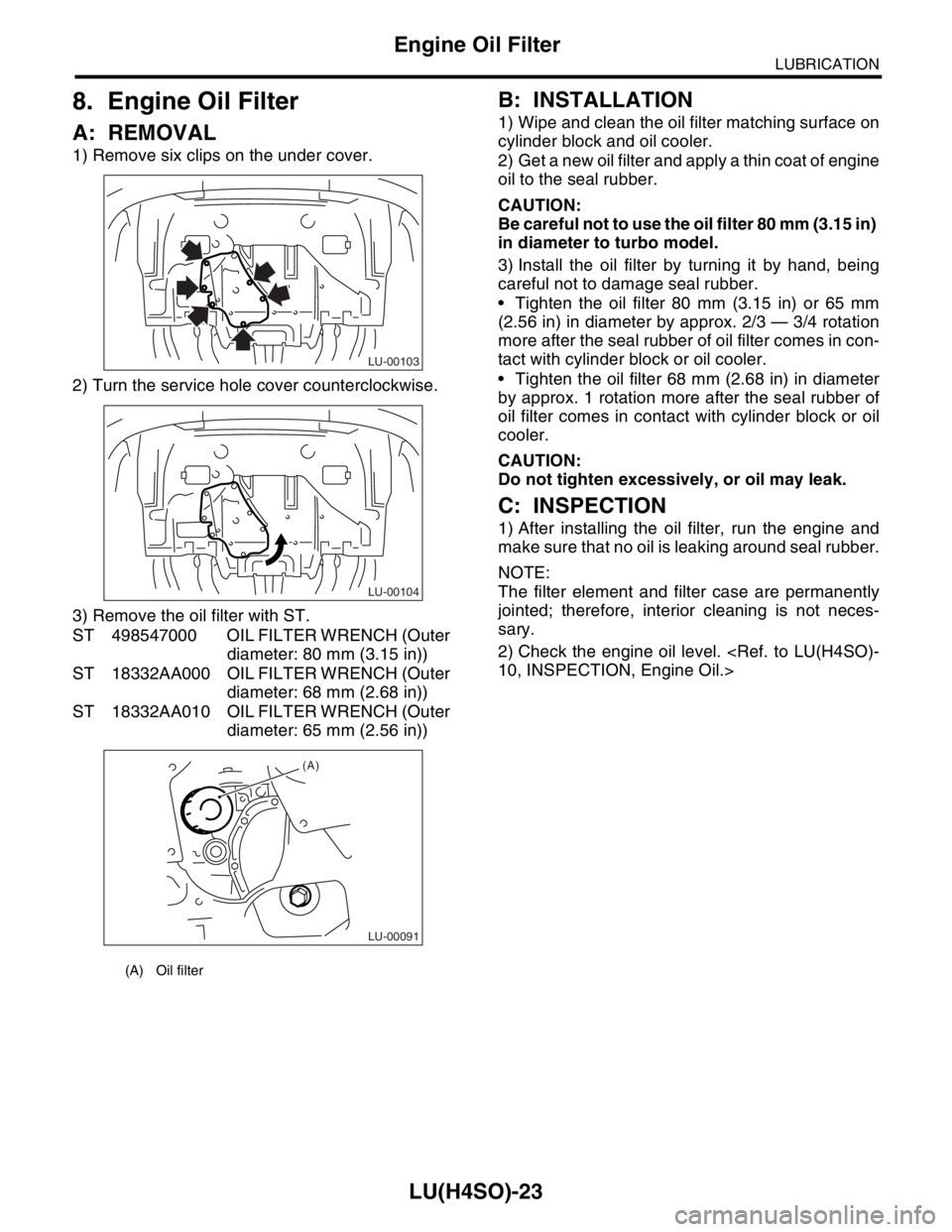
1) Remove six clips on the under cover.
2) Turn the service hole cover counterclockwise.
3) Remove the oil filter with ST.
ST 498547000 OIL FILTER WRENCH (Outer
diameter: 80 mm (3.15 in))
ST 18332AA000 OIL FILTER WRENCH (Outer
diameter: 68 mm (2.68 in))
ST 18332AA010 OIL FILTER WRENCH (Outer
diameter: 65 mm (2.56 in))
B: INSTALLATION
1) Wipe and clean the oil filter matching surface on
cylinder block and oil cooler.
2) Get a new oil filter and apply a thin coat of engine
oil to the seal rubber.
CAUTION:
Be careful not to use the oil filter 80 mm (3.15 in)
in diameter to turbo model.
3) Install the oil filter by turning it by hand, being
careful not to damage seal rubber.
Tighten the oil filter 80 mm (3.15 in) or 65 mm
(2.56 in) in diameter by approx. 2/3 — 3/4 rotation
more after the seal rubber of oil filter comes in con-
tact with cylinder block or oil cooler.
Tighten the oil filter 68 mm (2.68 in) in diameter
by approx. 1 rotation more after the seal rubber of
oil filter comes in contact with cylinder block or oil
cooler.
CAUTION:
Do not tighten excessively, or oil may leak.
C: INSPECTION
1) After installing the oil filter, run the engine and
make sure that no oil is leaking around seal rubber.
NOTE:
The filter element and filter case are permanently
jointed; therefore, interior cleaning is not neces-
sary.
2) Check the engine oil level.
(A) Oil filter
LU-00103
LU-00104
LU-00091
(A)
Page 1052 of 2870

LU(H4SO)-24
LUBRICATION
Engine Lubrication System Trouble in General
9. Engine Lubrication System Trouble in General
A: INSPECTION
Before performing diagnostics, make sure that the engine oil level is correct and no oil leakage exists.
Trouble Possible cause Corrective action
1. Warning light remains
on.1) Oil pressure switch
failureCracked diaphragm or oil leakage within switch Replace.
Broken spring or seized contacts Replace.
2) Low oil pressureClogged oil filter Replace.
Malfunction of oil by-pass valve of oil filter Clean or replace.
Malfunction of oil relief valve of oil pump Clean or replace.
Clogged oil passage Clean.
Excessive tip clearance and side clearance of oil
pump rotor and gearReplace.
Clogged oil strainer or broken pipe Clean or replace.
3) No oil pressureInsufficient engine oil Replenish.
Broken pipe of oil strainer Replace.
Stuck oil pump rotor Replace.
2. Warning light does
not go on.1) Malfunction of combination meter Replace.
2) Poor contact of switch contact points Replace.
3) Disconnection of wiring Repair.
3. Warning light flickers
momentarily.1) Poor contact at terminals Repair.
2) Defective wiring harness Repair.
3) Low oil pressureCheck for the same
possible causes as
listed in 1. — 2).
Page 1070 of 2870
IG(H4SO)-6
IGNITION
Spark Plug
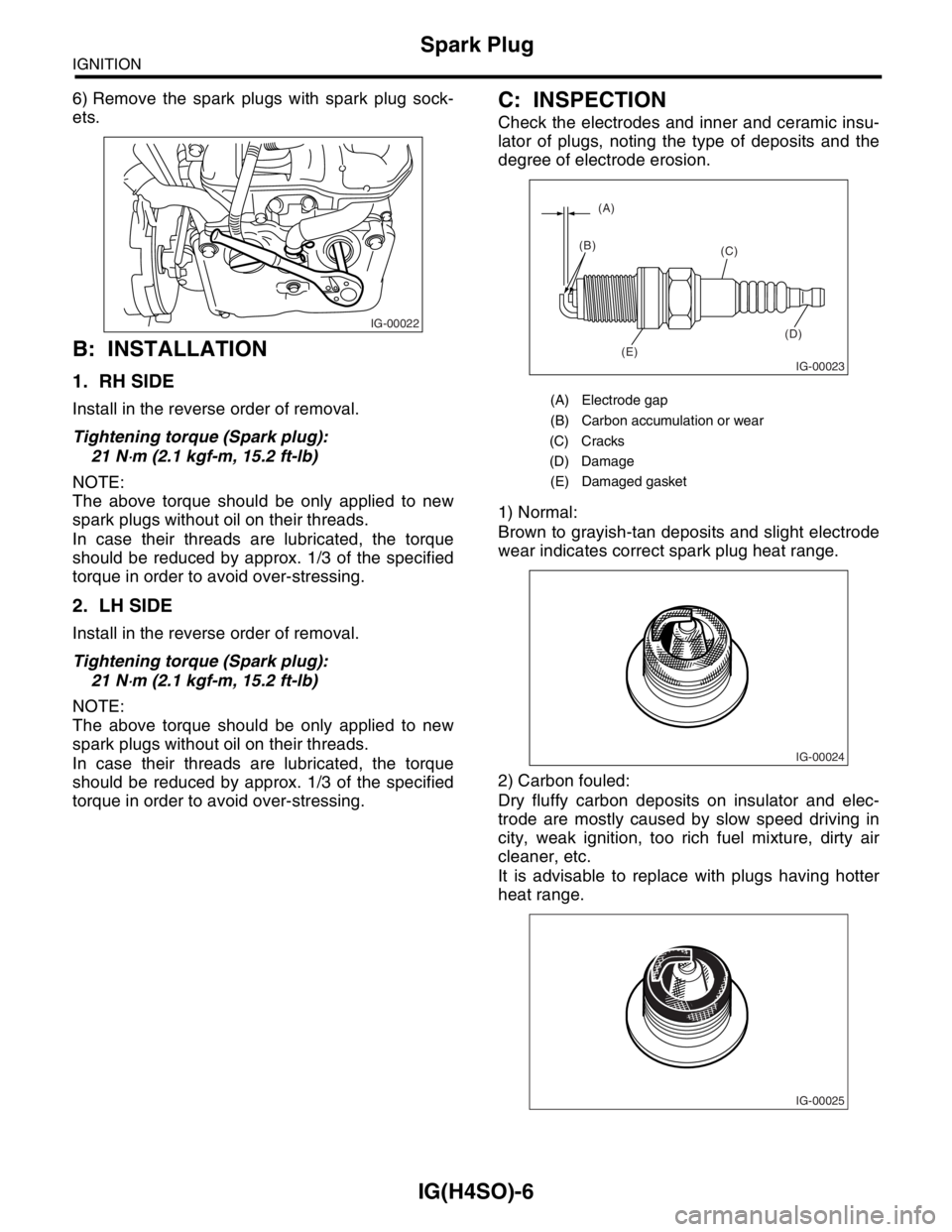
6) Remove the spark plugs with spark plug sock-
ets.
B: INSTALLATION
1. RH SIDE
Install in the reverse order of removal.
Tightening torque (Spark plug):
21 N
⋅m (2.1 kgf-m, 15.2 ft-lb)
NOTE:
The above torque should be only applied to new
spark plugs without oil on their threads.
In case their threads are lubricated, the torque
should be reduced by approx. 1/3 of the specified
torque in order to avoid over-stressing.
2. LH SIDE
Install in the reverse order of removal.
Tightening torque (Spark plug):
21 N
⋅m (2.1 kgf-m, 15.2 ft-lb)
NOTE:
The above torque should be only applied to new
spark plugs without oil on their threads.
In case their threads are lubricated, the torque
should be reduced by approx. 1/3 of the specified
torque in order to avoid over-stressing.
C: INSPECTION
Check the electrodes and inner and ceramic insu-
lator of plugs, noting the type of deposits and the
degree of electrode erosion.
1) Normal:
Brown to grayish-tan deposits and slight electrode
wear indicates correct spark plug heat range.
2) Carbon fouled:
Dry fluffy carbon deposits on insulator and elec-
trode are mostly caused by slow speed driving in
city, weak ignition, too rich fuel mixture, dirty air
cleaner, etc.
It is advisable to replace with plugs having hotter
heat range.
IG-00022
(A) Electrode gap
(B) Carbon accumulation or wear
(C) Cracks
(D) Damage
(E) Damaged gasket
IG-00023
(A)
(B)
(C)
(D)
(E)
IG-00024
IG-00025
Page 1087 of 2870
SC(H4SO)-12
STARTING/CHARGING SYSTEM
Starter
2. YOKE
Make sure the pole is set in position.
3. OVERRUNNING CLUTCH
Inspect the teeth of pinion for wear and damage.
Replace if it is damaged. Rotate the pinion in direc-
tion of rotation (counterclockwise). It should rotate
smoothly. But in opposite direction, it should be
locked.
CAUTION:
Do not clean the overrunning clutch with oil to
prevent grease from flowing out.
4. BRUSH AND BRUSH HOLDER
1) Brush length
Measure the brush length, and then replace if it ex-
ceeds the service limit.
Replace if abnormal wear or cracks are noticed.
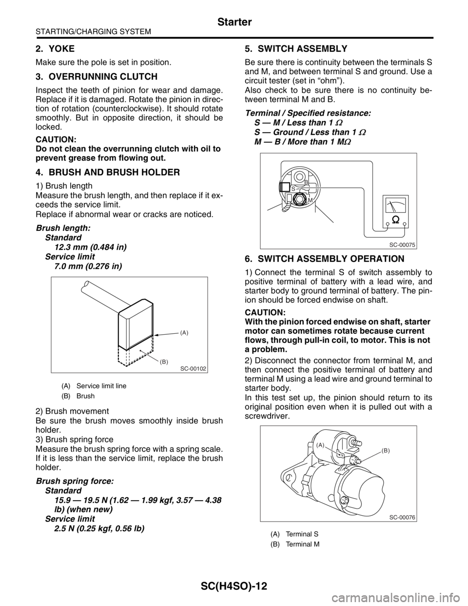
Brush length:
Standard
12.3 mm (0.484 in)
Service limit
7.0 mm (0.276 in)
2) Brush movement
Be sure the brush moves smoothly inside brush
holder.
3) Brush spring force
Measure the brush spring force with a spring scale.
If it is less than the service limit, replace the brush
holder.
Brush spring force:
Standard
15.9 — 19.5 N (1.62 — 1.99 kgf, 3.57 — 4.38
lb) (when new)
Service limit
2.5 N (0.25 kgf, 0.56 lb)
5. SWITCH ASSEMBLY
Be sure there is continuity between the terminals S
and M, and between terminal S and ground. Use a
circuit tester (set in “ohm”).
Also check to be sure there is no continuity be-
tween terminal M and B.
Terminal / Specified resistance:
S — M / Less than 1
Ω
S — Ground / Less than 1 Ω
M — B / More than 1 MΩ
6. SWITCH ASSEMBLY OPERATION
1) Connect the terminal S of switch assembly to
positive terminal of battery with a lead wire, and
starter body to ground terminal of battery. The pin-
ion should be forced endwise on shaft.
CAUTION:
With the pinion forced endwise on shaft, starter
motor can sometimes rotate because current
flows, through pull-in coil, to motor. This is not
a problem.
2) Disconnect the connector from terminal M, and
then connect the positive terminal of battery and
terminal M using a lead wire and ground terminal to
starter body.
In this test set up, the pinion should return to its
original position even when it is pulled out with a
screwdriver.
(A) Service limit line
(B) Brush
SC-00102
(A)
(B)
(A) Terminal S
(B) Terminal M
SC-00075
B
M
S
SC-00076
(B) (A)
Page 1093 of 2870
SC(H4SO)-18
STARTING/CHARGING SYSTEM
Generator
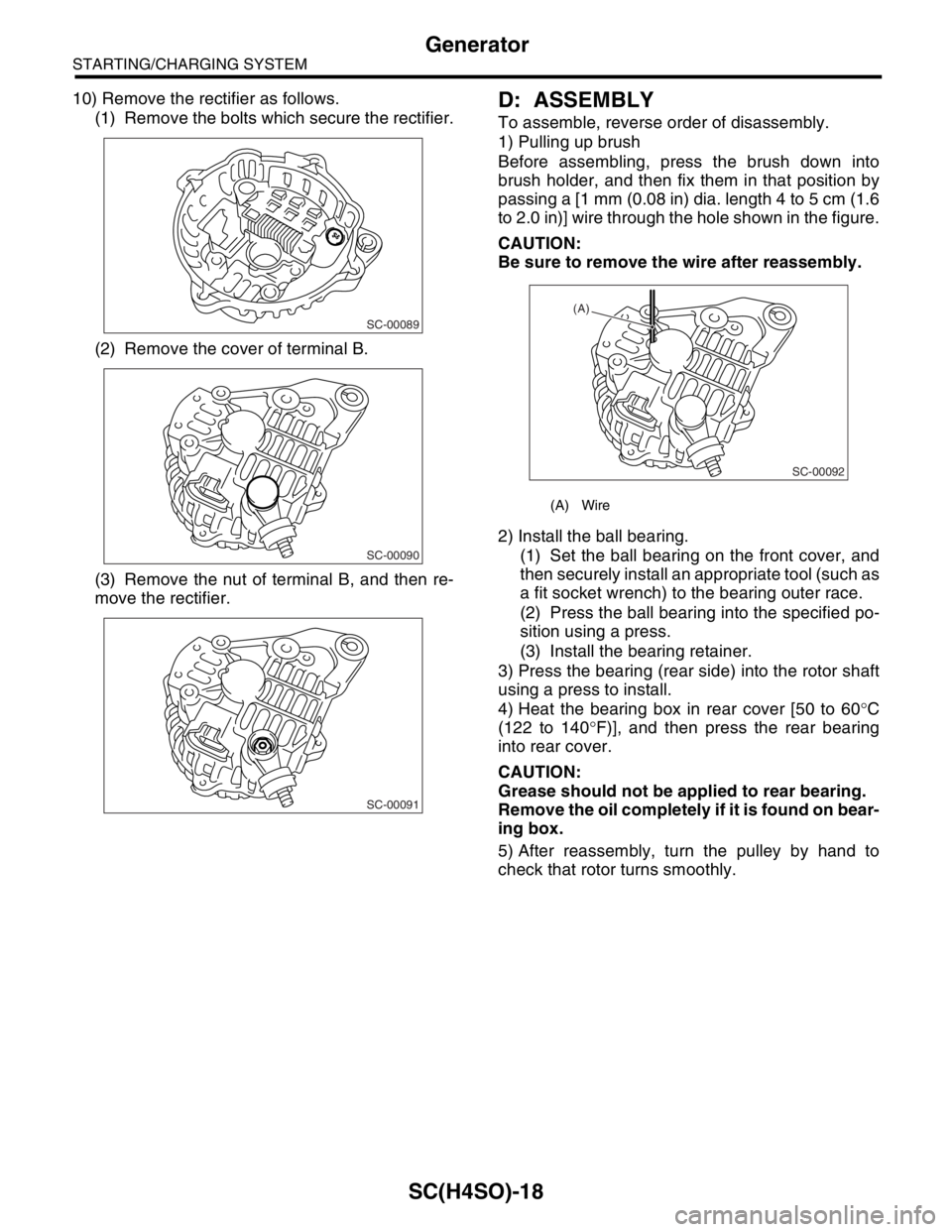
10) Remove the rectifier as follows.
(1) Remove the bolts which secure the rectifier.
(2) Remove the cover of terminal B.
(3) Remove the nut of terminal B, and then re-
move the rectifier.D: ASSEMBLY
To assemble, reverse order of disassembly.
1) Pulling up brush
Before assembling, press the brush down into
brush holder, and then fix them in that position by
passing a [1 mm (0.08 in) dia. length 4 to 5 cm (1.6
to 2.0 in)] wire through the hole shown in the figure.
CAUTION:
Be sure to remove the wire after reassembly.
2) Install the ball bearing.
(1) Set the ball bearing on the front cover, and
then securely install an appropriate tool (such as
a fit socket wrench) to the bearing outer race.
(2) Press the ball bearing into the specified po-
sition using a press.
(3) Install the bearing retainer.
3) Press the bearing (rear side) into the rotor shaft
using a press to install.
4) Heat the bearing box in rear cover [50 to 60°C
(122 to 140°F)], and then press the rear bearing
into rear cover.
CAUTION:
Grease should not be applied to rear bearing.
Remove the oil completely if it is found on bear-
ing box.
5) After reassembly, turn the pulley by hand to
check that rotor turns smoothly.
SC-00089
SC-00090
SC-00091
(A) Wire
SC-00092
(A)
Page 1094 of 2870
SC(H4SO)-19
STARTING/CHARGING SYSTEM
Generator
E: INSPECTION
1. DIODE
CAUTION:
Never use a mega tester (measuring use for
high voltage) or any other similar measure for
this test; otherwise, the diodes may be dam-
aged.
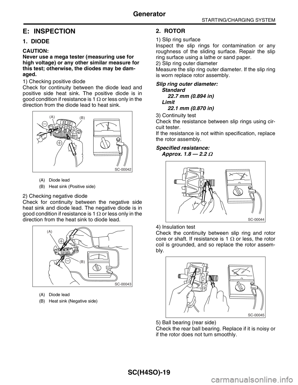
1) Checking positive diode
Check for continuity between the diode lead and
positive side heat sink. The positive diode is in
good condition if resistance is 1 Ω or less only in the
direction from the diode lead to heat sink.
2) Checking negative diode
Check for continuity between the negative side
heat sink and diode lead. The negative diode is in
good condition if resistance is 1 Ω or less only in the
direction from the heat sink to diode lead.
2. ROTOR
1) Slip ring surface
Inspect the slip rings for contamination or any
roughness of the sliding surface. Repair the slip
ring surface using a lathe or sand paper.
2) Slip ring outer diameter
Measure the slip ring outer diameter. If the slip ring
is worn replace rotor assembly.
Slip ring outer diameter:
Standard
22.7 mm (0.894 in)
Limit
22.1 mm (0.870 in)
3) Continuity test
Check the resistance between slip rings using cir-
cuit tester.
If the resistance is not within specification, replace
the rotor assembly.
Specified resistance:
Approx. 1.8 — 2.2
Ω
4) Insulation test
Check the continuity between slip ring and rotor
core or shaft. If resistance is 1 Ω or less, the rotor
coil is grounded, and so replace the rotor assem-
bly.
5) Ball bearing (rear side)
Check the rear ball bearing. Replace if it is noisy or
if the rotor does not turn smoothly.
(A) Diode lead
(B) Heat sink (Positive side)
(A) Diode lead
(B) Heat sink (Negative side)
(A)
(B)
SC-00042
(B) (A)
SC-00043
SC-00044
SC-00045
Page 1095 of 2870
SC(H4SO)-20
STARTING/CHARGING SYSTEM
Generator
3. STARTOR
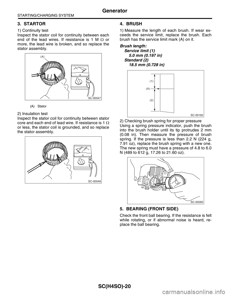
1) Continuity test
Inspect the stator coil for continuity between each
end of the lead wires. If resistance is 1 M Ω or
more, the lead wire is broken, and so replace the
stator assembly.
2) Insulation test
Inspect the stator coil for continuity between stator
core and each end of lead wire. If resistance is 1 Ω
or less, the stator coil is grounded, and so replace
the stator assembly.
4. BRUSH
1) Measure the length of each brush. If wear ex-
ceeds the service limit, replace the brush. Each
brush has the service limit mark (A) on it.
Brush length:
Service limit (1)
5.0 mm (0.197 in)
Standard (2)
18.5 mm (0.728 in)
2) Checking brush spring for proper pressure
Using a spring pressure indicator, push the brush
into the brush holder until its tip protrudes 2 mm
(0.08 in). Then measure the pressure of brush
spring. If the pressure is less than 2.2 N (224 g,
7.91 oz), replace the brush spring with a new one.
The new spring must have a pressure of 4.8 to 6.0
N (489 to 612 g, 17.26 to 21.60 oz).
5. BEARING (FRONT SIDE)
Check the front ball bearing. If the resistance is felt
while rotating, or if abnormal noise is heard, re-
place the ball bearing.
(A) Stator
(A)
SC-00047
SC-00048
SC-00162
(A)
(1)
(2)
SC-00093
Page 1101 of 2870

EN(H4SO)-3
ENGINE (DIAGNOSTIC)
Basic Diagnostics Procedure
2. AUTOMATIC TRANSMISSION
When the DTC about automatic transmission is
shown on display, carry out the following basic
check. After that, carry out the replacement or re-
pair work.
1) ATF level check
2) Differential gear oil level check
3) ATF leak check
4) Differential gear oil level check
5) Stall Test
6) Line Pressure Test
7) Transfer Clutch Pressure Test
8) Time Lag Test
9) Road Test
10) Shift characteristics