Page 780 of 2870
PM-43
PERIODIC MAINTENANCE SERVICE
Steering System (Power Steering)
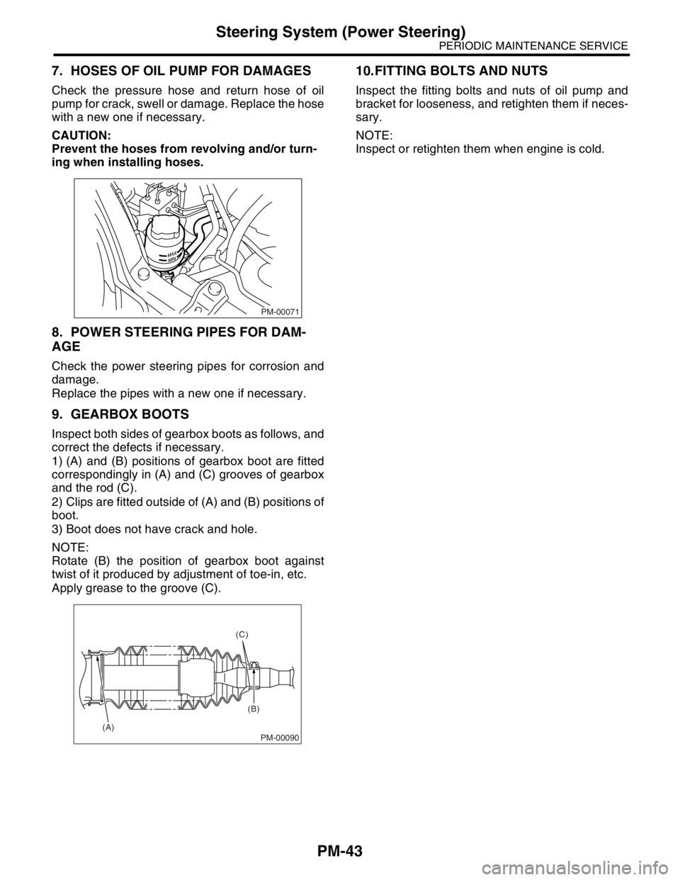
7. HOSES OF OIL PUMP FOR DAMAGES
Check the pressure hose and return hose of oil
pump for crack, swell or damage. Replace the hose
with a new one if necessary.
CAUTION:
Prevent the hoses from revolving and/or turn-
ing when installing hoses.
8. POWER STEERING PIPES FOR DAM-
AGE
Check the power steering pipes for corrosion and
damage.
Replace the pipes with a new one if necessary.
9. GEARBOX BOOTS
Inspect both sides of gearbox boots as follows, and
correct the defects if necessary.
1) (A) and (B) positions of gearbox boot are fitted
correspondingly in (A) and (C) grooves of gearbox
and the rod (C).
2) Clips are fitted outside of (A) and (B) positions of
boot.
3) Boot does not have crack and hole.
NOTE:
Rotate (B) the position of gearbox boot against
twist of it produced by adjustment of toe-in, etc.
Apply grease to the groove (C).
10.FITTING BOLTS AND NUTS
Inspect the fitting bolts and nuts of oil pump and
bracket for looseness, and retighten them if neces-
sary.
NOTE:
Inspect or retighten them when engine is cold.
PM-00071
PM-00090
(C)
(B)
(A)
Page 884 of 2870
ME(H4SO)-15
MECHANICAL
General Description
C: CAUTION
Wear working clothing, including a cap, protec-
tive goggles and protective shoes during operation.
Remove contamination including dirt and corro-
sion before removal, installation or disassembly.
Keep the disassembled parts in order and pro-
tect them from dust or dirt.
Before removal, installation or disassembly, be
sure to clarify the failure. Avoid unnecessary re-
moval, installation, disassembly and replacement.
Be careful not to burn yourself, because each
part in the vehicle is hot after running.
Be sure to tighten bolts and nuts to the specified
torque.
Place shop jacks or rigid racks at the specified
points.
Before disconnecting electrical connectors of
sensors or units, be sure to disconnect the ground
cable from battery.
All parts should be thoroughly cleaned, paying
special attention to the engine oil passages, pis-
tons and bearings. Rotating parts and sliding parts such as piston,
bearing and gear should be coated with oil prior to
assembly.
Be careful not to let oil, grease or coolant contact
the timing belt, clutch disc and flywheel.
All removed parts, if to be reused, should be re-
installed in the original positions and directions.
Bolts, nuts and washers should be replaced with
new ones as required.
Even if necessary inspections have been made
in advance, proceed with assembly work while
making rechecks.
Remove or install engine in an area where chain
hoists, lifting devices, etc. are available for ready
use.
Be sure not to damage coated surfaces of body
panels with tools, or not to stain seats and windows
with coolant or oil. Place a cover over fenders, as
required, for protection.
Prior to starting work, prepare the following:
Service tools, clean cloth, containers to catch cool-
ant and oil, wire ropes, chain hoist, transmission
jacks, etc.
Lift-up or lower the vehicle when necessary.
Make sure to support the correct positions.
D: PREPARATION TOOL
1. SPECIAL TOOL
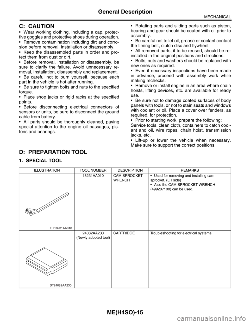
ILLUSTRATION TOOL NUMBER DESCRIPTION REMARKS
18231AA010 CAM SPROCKET
WRENCH Used for removing and installing cam
sprocket. (LH side)
Also the CAM SPROCKET WRENCH
(499207100) can be used.
24082AA230
(Newly adopted tool)CARTRIDGE Troubleshooting for electrical systems.
ST18231AA010
ST24082AA230
Page 898 of 2870
ME(H4SO)-29
MECHANICAL
Engine Oil Pressure
6. Engine Oil Pressure
A: INSPECTION
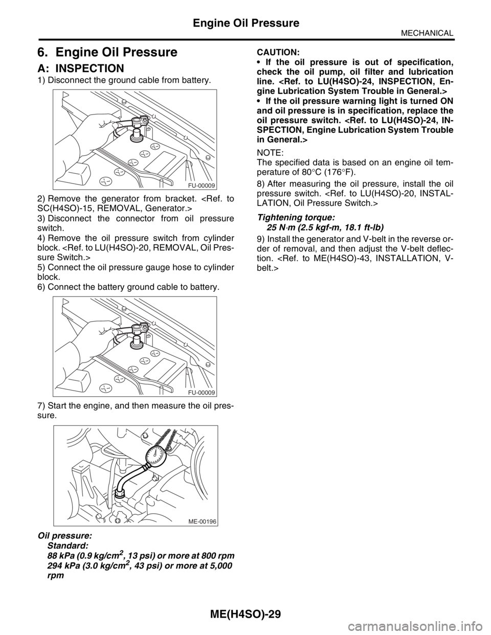
1) Disconnect the ground cable from battery.
2) Remove the generator from bracket.
SC(H4SO)-15, REMOVAL, Generator.>
3) Disconnect the connector from oil pressure
switch.
4) Remove the oil pressure switch from cylinder
block.
sure Switch.>
5) Connect the oil pressure gauge hose to cylinder
block.
6) Connect the battery ground cable to battery.
7) Start the engine, and then measure the oil pres-
sure.
Oil pressure:
Standard:
88 kPa (0.9 kg/cm
2, 13 psi) or more at 800 rpm
294 kPa (3.0 kg/cm2, 43 psi) or more at 5,000
rpmCAUTION:
If the oil pressure is out of specification,
check the oil pump, oil filter and lubrication
line.
gine Lubrication System Trouble in General.>
If the oil pressure warning light is turned ON
and oil pressure is in specification, replace the
oil pressure switch.
SPECTION, Engine Lubrication System Trouble
in General.>
NOTE:
The specified data is based on an engine oil tem-
perature of 80°C (176°F).
8) After measuring the oil pressure, install the oil
pressure switch.
LATION, Oil Pressure Switch.>
Tightening torque:
25 N
⋅m (2.5 kgf-m, 18.1 ft-lb)
9) Install the generator and V-belt in the reverse or-
der of removal, and then adjust the V-belt deflec-
tion.
belt.>
FU-00009
FU-00009
ME-00196
Page 913 of 2870
ME(H4SO)-44
MECHANICAL
V-belt
2) Tighten the lock nut (A).
Tightening torque:
Lock nut (A)
22.6 N
⋅m (2.3 kgf-m, 16.6 ft-lb)
C: INSPECTION
1) Replace the belts, if cracks, fraying or wear is
found.
2) Check the drive belt tension and adjust it if nec-
essary by changing the generator installing position
or idler pulley installing position.
Belt tension
(A)
replaced: 7 — 9 mm (0.276 — 0.354 in)
reused: 9 — 11 mm (0.354 — 0.433 in)
(B)
replaced: 7.5 — 8.5 mm (0.295 — 0.335 in)
reused: 9.0 — 10.0 mm (0.354 — 0.394 in)
C/P Crank pulley
GEN Generator
P/S Power steering oil pump pulley
A/C Air conditioning compressor pulley
I/P Idler pulley
ME-00224
(A) (B)
ME-00226
(A) (B)(C)GEN
C/P
I/P A/C
P/S
Page 915 of 2870
ME(H4SO)-46
MECHANICAL
Crank Pulley
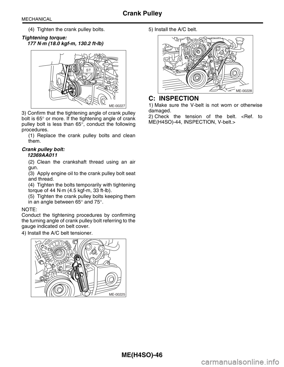
(4) Tighten the crank pulley bolts.
Tightening torque:
177 N
⋅m (18.0 kgf-m, 130.2 ft-lb)
3) Confirm that the tightening angle of crank pulley
bolt is 65° or more. If the tightening angle of crank
pulley bolt is less than 65°, conduct the following
procedures.
(1) Replace the crank pulley bolts and clean
them.
Crank pulley bolt:
12369AA011
(2) Clean the crankshaft thread using an air
gun.
(3) Apply engine oil to the crank pulley bolt seat
and thread.
(4) Tighten the bolts temporarily with tightening
torque of 44 N⋅m (4.5 kgf-m, 33 ft-lb).
(5) Tighten the crank pulley bolts keeping them
in an angle between 65° and 75°.
NOTE:
Conduct the tightening procedures by confirming
the turning angle of crank pulley bolt referring to the
gauge indicated on belt cover.
4) Install the A/C belt tensioner.5) Install the A/C belt.
C: INSPECTION
1) Make sure the V-belt is not worn or otherwise
damaged.
2) Check the tension of the belt.
ME(H4SO)-44, INSPECTION, V-belt.>ME-00227
STST
ME-00225
ME-00228
Page 920 of 2870
ME(H4SO)-51
MECHANICAL
Timing Belt
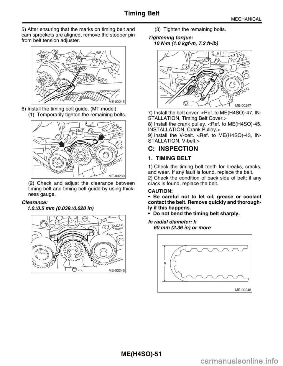
5) After ensuring that the marks on timing belt and
cam sprockets are aligned, remove the stopper pin
from belt tension adjuster.
6) Install the timing belt guide. (MT model)
(1) Temporarily tighten the remaining bolts.
(2) Check and adjust the clearance between
timing belt and timing belt guide by using thick-
ness gauge.
Clearance:
1.0
±0.5 mm (0.039±0.020 in)(3) Tighten the remaining bolts.
Tightening torque:
10 N
⋅m (1.0 kgf-m, 7.2 ft-lb)
7) Install the belt cover.
STALLATION, Timing Belt Cover.>
8) Install the crank pulley.
INSTALLATION, Crank Pulley.>
9) Install the V-belt.
STALLATION, V-belt.>
C: INSPECTION
1. TIMING BELT
1) Check the timing belt teeth for breaks, cracks,
and wear. If any fault is found, replace the belt.
2) Check the condition of back side of belt; if any
crack is found, replace the belt.
CAUTION:
Be careful not to let oil, grease or coolant
contact the belt. Remove quickly and thorough-
ly if this happens.
Do not bend the timing belt sharply.
In radial diameter: h
60 mm (2.36 in) or more
ME-00245
ME-00230
ME-00246
ME-00247
ME-00248
h
Page 921 of 2870
ME(H4SO)-52
MECHANICAL
Timing Belt
2. AUTOMATIC BELT TENSION ADJUST-
ER
1) Visually check oil seals for leaks, and rod ends
for abnormal wear or scratches. If necessary, re-
place faulty parts.
2) Check that the adjuster rod does not move when
a pressure of 294 N (30 kgf, 66 lb) is applied to it.
This is to check adjuster rod stiffness.
3) If the adjuster rod is not stiff and moves freely
when applying 294 N (30 kgf, 66 lb), check it using
the following procedures:
(1) Slowly press the adjuster rod down to the
end surface of the cylinder. Repeat this motion 2
or 3 times.
(2) With the adjuster rod moved all the way up,
apply a pressure of 294 N (30 kgf, 66 lb) to it.
Check adjuster rod stiffness.
(3) If the adjuster rod is not stiff and moves
down, replace the automatic belt tension adjust-
er assembly with a new one.
CAUTION:
Always use a vertical type pressing tool to
move the adjuster rod down.
Do not use a lateral type vise.
Push the adjuster rod vertically.
Press-in the adjuster rod gradually taking
more than 3 minutes.
Do not allow press pressure to exceed 9,807
N (1,000 kgf, 2,205 lb).
Press the adjuster rod as far as the end sur-
face of the cylinder. Do not press the adjuster
rod into the cylinder. Doing so may damage the
cylinder.
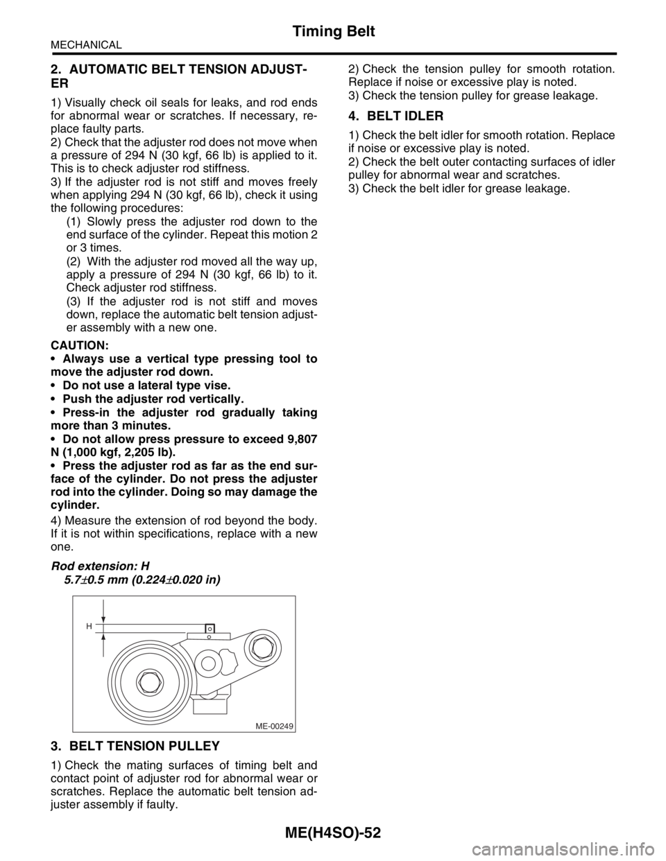
4) Measure the extension of rod beyond the body.
If it is not within specifications, replace with a new
one.
Rod extension: H
5.7
±0.5 mm (0.224±0.020 in)
3. BELT TENSION PULLEY
1) Check the mating surfaces of timing belt and
contact point of adjuster rod for abnormal wear or
scratches. Replace the automatic belt tension ad-
juster assembly if faulty.2) Check the tension pulley for smooth rotation.
Replace if noise or excessive play is noted.
3) Check the tension pulley for grease leakage.
4. BELT IDLER
1) Check the belt idler for smooth rotation. Replace
if noise or excessive play is noted.
2) Check the belt outer contacting surfaces of idler
pulley for abnormal wear and scratches.
3) Check the belt idler for grease leakage.
ME-00249
H
Page 928 of 2870
ME(H4SO)-57
MECHANICAL
Valve Rocker Assembly
D: ASSEMBLY
1) Install the adjusting screw and nut to valve rock-
er.
2) Arrange the valve rocker arms, springs and shaft
supports in assembly order and insert valve rocker
shaft.
Tightening torque (Shaft supports installing
bolts):
5 N
⋅m (0.5 kgf-m, 3.6 ft-lb)
NOTE:
Valve rocker arms, rocker shaft and shaft supports
have identification marks. Ensure the parts with
same markings are properly assembled.
3) Install the valve rocker shaft securing bolts.
E: INSPECTION
1. VALVE ROCKER ARM AND ROCKER
SHAFT
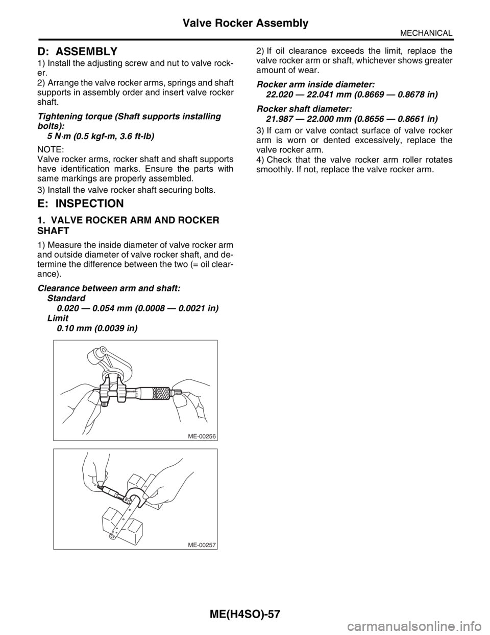
1) Measure the inside diameter of valve rocker arm
and outside diameter of valve rocker shaft, and de-
termine the difference between the two (= oil clear-
ance).
Clearance between arm and shaft:
Standard
0.020 — 0.054 mm (0.0008 — 0.0021 in)
Limit
0.10 mm (0.0039 in)2) If oil clearance exceeds the limit, replace the
valve rocker arm or shaft, whichever shows greater
amount of wear.
Rocker arm inside diameter:
22.020 — 22.041 mm (0.8669 — 0.8678 in)
Rocker shaft diameter:
21.987 — 22.000 mm (0.8656 — 0.8661 in)
3) If cam or valve contact surface of valve rocker
arm is worn or dented excessively, replace the
valve rocker arm.
4) Check that the valve rocker arm roller rotates
smoothly. If not, replace the valve rocker arm.
ME-00256
ME-00257