Page 959 of 2870
ME(H4SO)-88
MECHANICAL
Cylinder Block
Connecting rod oil clearance:
Standard
0.0158 — 0.0438 mm (0.0006 — 0.0017 in)
Limit
0.05 mm (0.0020 in)
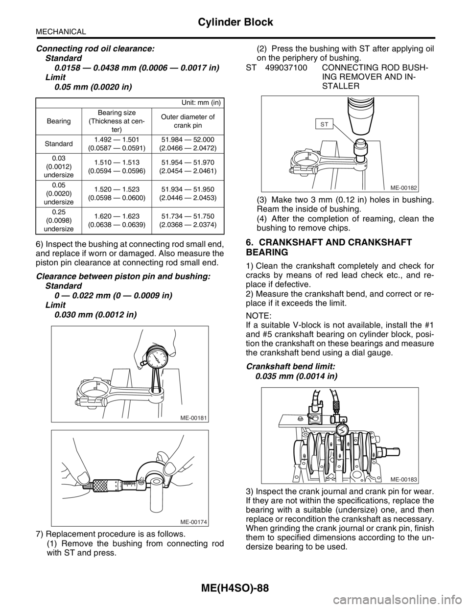
6) Inspect the bushing at connecting rod small end,
and replace if worn or damaged. Also measure the
piston pin clearance at connecting rod small end.
Clearance between piston pin and bushing:
Standard
0 — 0.022 mm (0 — 0.0009 in)
Limit
0.030 mm (0.0012 in)
7) Replacement procedure is as follows.
(1) Remove the bushing from connecting rod
with ST and press.(2) Press the bushing with ST after applying oil
on the periphery of bushing.
ST 499037100 CONNECTING ROD BUSH-
ING REMOVER AND IN-
STALLER
(3) Make two 3 mm (0.12 in) holes in bushing.
Ream the inside of bushing.
(4) After the completion of reaming, clean the
bushing to remove chips.
6. CRANKSHAFT AND CRANKSHAFT
BEARING
1) Clean the crankshaft completely and check for
cracks by means of red lead check etc., and re-
place if defective.
2) Measure the crankshaft bend, and correct or re-
place if it exceeds the limit.
NOTE:
If a suitable V-block is not available, install the #1
and #5 crankshaft bearing on cylinder block, posi-
tion the crankshaft on these bearings and measure
the crankshaft bend using a dial gauge.
Crankshaft bend limit:
0.035 mm (0.0014 in)
3) Inspect the crank journal and crank pin for wear.
If they are not within the specifications, replace the
bearing with a suitable (undersize) one, and then
replace or recondition the crankshaft as necessary.
When grinding the crank journal or crank pin, finish
them to specified dimensions according to the un-
dersize bearing to be used.
Unit: mm (in)
BearingBearing size
(Thickness at cen-
ter)Outer diameter of
crank pin
Standard1.492 — 1.501
(0.0587 — 0.0591)51.984 — 52.000
(2.0466 — 2.0472)
0.03
(0.0012)
undersize1.510 — 1.513
(0.0594 — 0.0596)51.954 — 51.970
(2.0454 — 2.0461)
0.05
(0.0020)
undersize1.520 — 1.523
(0.0598 — 0.0600)51.934 — 51.950
(2.0446 — 2.0453)
0.25
(0.0098)
undersize1.620 — 1.623
(0.0638 — 0.0639)51.734 — 51.750
(2.0368 — 2.0374)
ME-00181
ME-00174
ME-00182
ST
ME-00183
Page 1016 of 2870
CO(H4SO)-33
COOLING
Radiator
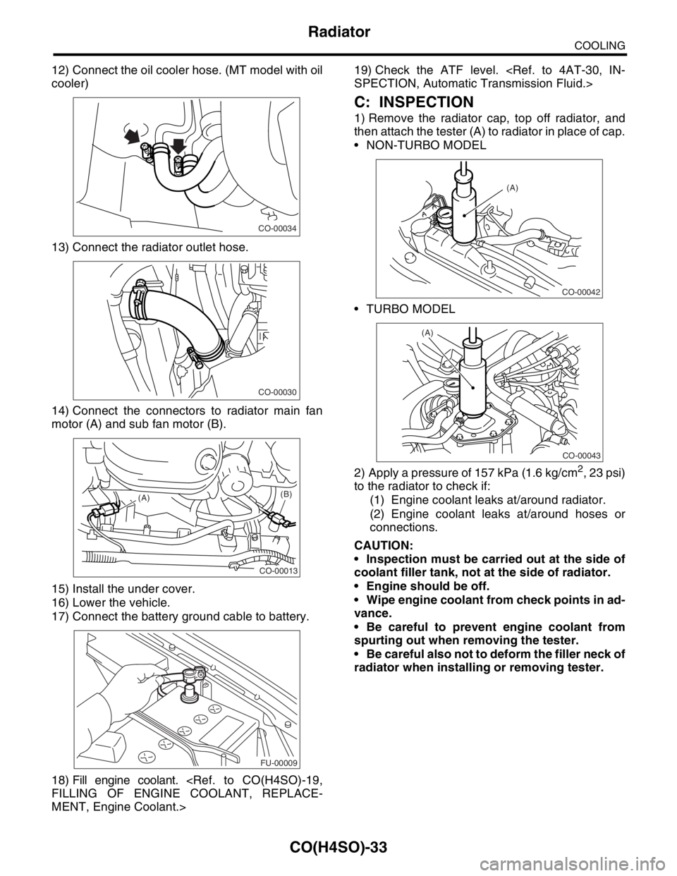
12) Connect the oil cooler hose. (MT model with oil
cooler)
13) Connect the radiator outlet hose.
14) Connect the connectors to radiator main fan
motor (A) and sub fan motor (B).
15) Install the under cover.
16) Lower the vehicle.
17) Connect the battery ground cable to battery.
18) Fill engine coolant.
FILLING OF ENGINE COOLANT, REPLACE-
MENT, Engine Coolant.>19) Check the ATF level.
SPECTION, Automatic Transmission Fluid.>
C: INSPECTION
1) Remove the radiator cap, top off radiator, and
then attach the tester (A) to radiator in place of cap.
NON-TURBO MODEL
TURBO MODEL
2) Apply a pressure of 157 kPa (1.6 kg/cm
2, 23 psi)
to the radiator to check if:
(1) Engine coolant leaks at/around radiator.
(2) Engine coolant leaks at/around hoses or
connections.
CAUTION:
Inspection must be carried out at the side of
coolant filler tank, not at the side of radiator.
Engine should be off.
Wipe engine coolant from check points in ad-
vance.
Be careful to prevent engine coolant from
spurting out when removing the tester.
Be careful also not to deform the filler neck of
radiator when installing or removing tester.
CO-00034
CO-00030
CO-00013
(A)(B)
FU-00009
CO-00042
(A)
CO-00043
(A)
Page 1037 of 2870

LU(H4SO)-9
LUBRICATION
Oil Pressure System
B: INSPECTION
Step Check Yes No
1 CHECK COMBINATION METER.
1) Turn the ignition switch to ON. (engine
OFF)
2) Check other warning lights.Does the warning lights illumi-
nate?Go to step 2.Repair or replace
the combination
meter.
4, INSPECTION,
Combination
Meter System.>
2 CHECK HARNESS CONNECTOR BETWEEN
COMBINATION METER AND OIL PRES-
SURE SWITCH.
1) Turn the ignition switch to OFF.
2) Disconnect the connector from oil pressure
switch.
3) Turn the ignition switch to ON.
4) Measure the voltage of harness between
the combination meter connector and chassis
ground.
Connector & terminal
(E11) No. 1 (+) — Chassis ground (
−):Is the voltage more than 10 V? Replace the oil
pressure switch.Go to step 3.
3 CHECK COMBINATION METER.
1) Turn the ignition switch to OFF.
2) Remove the combination meter.
3) Measure the resistance of combination
meter.
Te r m i n a l
No. B9 — No. A3:Is the resistance less than 10
Ω?Replace the har-
ness connector
between combina-
tion meter and oil
pressure switch.Repair or replace
the combination
meter and the oil
pressure switch
warning light bulb.
Page 1038 of 2870
LU(H4SO)-10
LUBRICATION
Engine Oil
3. Engine Oil
A: INSPECTION
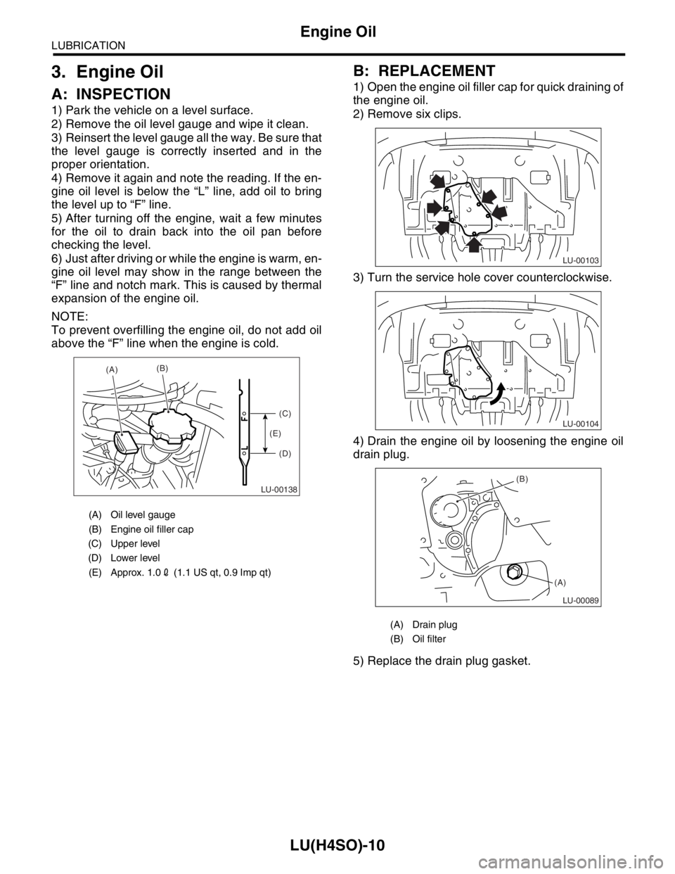
1) Park the vehicle on a level surface.
2) Remove the oil level gauge and wipe it clean.
3) Reinsert the level gauge all the way. Be sure that
the level gauge is correctly inserted and in the
proper orientation.
4) Remove it again and note the reading. If the en-
gine oil level is below the “L” line, add oil to bring
the level up to “F” line.
5) After turning off the engine, wait a few minutes
for the oil to drain back into the oil pan before
checking the level.
6) Just after driving or while the engine is warm, en-
gine oil level may show in the range between the
“F” line and notch mark. This is caused by thermal
expansion of the engine oil.
NOTE:
To prevent overfilling the engine oil, do not add oil
above the “F” line when the engine is cold.
B: REPLACEMENT
1) Open the engine oil filler cap for quick draining of
the engine oil.
2) Remove six clips.
3) Turn the service hole cover counterclockwise.
4) Drain the engine oil by loosening the engine oil
drain plug.
5) Replace the drain plug gasket.
(A) Oil level gauge
(B) Engine oil filler cap
(C) Upper level
(D) Lower level
(E) Approx. 1.02 (1.1 US qt, 0.9 Imp qt)
LU-00138
(A)(B)
(C)
(D) (E)
(A) Drain plug
(B) Oil filter
LU-00103
LU-00104
LU-00089
(B)
(A)
Page 1039 of 2870
LU(H4SO)-11
LUBRICATION
Engine Oil
6) Tighten the engine oil drain plug after draining
engine oil.
Tightening torque:
44 N
⋅m (4.5 kgf-m, 32.5 ft-lb)
7) Install the service hole cover.
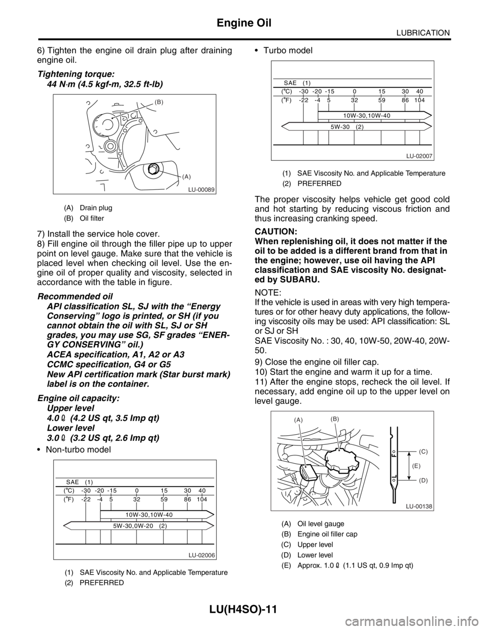
8) Fill engine oil through the filler pipe up to upper
point on level gauge. Make sure that the vehicle is
placed level when checking oil level. Use the en-
gine oil of proper quality and viscosity, selected in
accordance with the table in figure.
Recommended oil
API classification SL, SJ with the “Energy
Conserving” logo is printed, or SH (if you
cannot obtain the oil with SL, SJ or SH
grades, you may use SG, SF grades “ENER-
GY CONSERVING” oil.)
ACEA specification, A1, A2 or A3
CCMC specification, G4 or G5
New API certification mark (Star burst mark)
label is on the container.
Engine oil capacity:
Upper level
4.02 (4.2 US qt, 3.5 Imp qt)
Lower level
3.02 (3.2 US qt, 2.6 Imp qt)
Non-turbo model Turbo model
The proper viscosity helps vehicle get good cold
and hot starting by reducing viscous friction and
thus increasing cranking speed.
CAUTION:
When replenishing oil, it does not matter if the
oil to be added is a different brand from that in
the engine; however, use oil having the API
classification and SAE viscosity No. designat-
ed by SUBARU.
NOTE:
If the vehicle is used in areas with very high tempera-
tures or for other heavy duty applications, the follow-
ing viscosity oils may be used: API classification: SL
or SJ or SH
SAE Viscosity No. : 30, 40, 10W-50, 20W-40, 20W-
50.
9) Close the engine oil filler cap.
10) Start the engine and warm it up for a time.
11) After the engine stops, recheck the oil level. If
necessary, add engine oil up to the upper level on
level gauge.
(A) Drain plug
(B) Oil filter
(1) SAE Viscosity No. and Applicable Temperature
(2) PREFERRED
LU-00089
(B)
(A)
LU-02006
40 30 15 0 -15 -20 -30 ( C)
104 86 59 32
10W-30,10W-40 5 -4 -22 ( F)
SAE (1)
5W-30,0W-20 (2)
(1) SAE Viscosity No. and Applicable Temperature
(2) PREFERRED
(A) Oil level gauge
(B) Engine oil filler cap
(C) Upper level
(D) Lower level
(E) Approx. 1.02 (1.1 US qt, 0.9 Imp qt)
LU-02007
40 30 15 0 -15 -20 -30 ( C)
104 86 59 32 5 -4 -22 ( F)
SAE (1)
10W-30,10W-40
5W-30 (2)
LU-00138
(A)(B)
(C)
(D) (E)
Page 1043 of 2870
LU(H4SO)-15
LUBRICATION
Oil Pump
E: INSPECTION
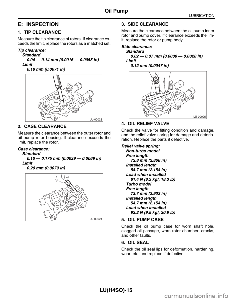
1. TIP CLEARANCE
Measure the tip clearance of rotors. If clearance ex-
ceeds the limit, replace the rotors as a matched set.
Tip clearance:
Standard
0.04 — 0.14 mm (0.0016 — 0.0055 in)
Limit
0.18 mm (0.0071 in)
2. CASE CLEARANCE
Measure the clearance between the outer rotor and
oil pump rotor housing. If clearance exceeds the
limit, replace the rotor.
Case clearance:
Standard
0.10 — 0.175 mm (0.0039 — 0.0069 in)
Limit
0.20 mm (0.0079 in)
3. SIDE CLEARANCE
Measure the clearance between the oil pump inner
rotor and pump cover. If clearance exceeds the lim-
it, replace the rotor or pump body.
Side clearance:
Standard
0.02 — 0.07 mm (0.0008 — 0.0028 in)
Limit
0.12 mm (0.0047 in)
4. OIL RELIEF VALVE
Check the valve for fitting condition and damage,
and the relief valve spring for damage and deterio-
ration. Replace the parts if defective.
Relief valve spring:
Non-turbo model
Free length
72.8 mm (2.866 in)
Installed length
54.7 mm (2.154 in)
Load when installed
81.4 N (8.3 kgf, 18.3 lb)
Turbo model
Free length
73.7 mm (2.902 in)
Installed length
54.7 mm (2.154 in)
Load when installed
93.2 N (9.5 kgf, 20.9 lb)
5. OIL PUMP CASE
Check the oil pump case for worn shaft hole,
clogged oil passage, worn rotor chamber, cracks,
and other faults.
6. OIL SEAL
Check the oil seal lips for deformation, hardening,
wear, etc. and replace if defective.
LU-00023
LU-00024
LU-00025
Page 1047 of 2870
LU(H4SO)-19
LUBRICATION
Oil Pan and Strainer
10) Remove the lifting device and steel cables.
11) Install the pitching stopper.
Tightening torque:
T1: 50 N
⋅m (5.1 kgf-m, 36.9 ft-lb)
T2: 58 N
⋅m (5.9 kgf-m, 42.8 ft-lb)
12) Install the radiator upper brackets.
13) Install the air intake duct and air cleaner case.
(Non-turbo model)
LATION, Air Intake Duct.>
INSTALLATION, Air Cleaner Case.>
14) Install the intercooler. (Turbo model)
IN(H4DOTC)-11, INSTALLATION, Intercooler.>15) Install the air intake boot and air cleaner upper
cover. (Turbo model)
16) Connect the connector to mass air flow sensor.
(Turbo model)
17) Install the front wheels.
18) Connect the battery ground cable to battery.
19) Fill engine oil.
TION, Engine Oil.>
C: INSPECTION
By visual check make sure the oil pan, oil strainer,
oil strainer stay and baffle plate are not damaged.
LU-00028
ME-00218T2T1
LU-00027
LU-00070
LU-00026
FU-00009
Page 1050 of 2870
LU(H4SO)-22
LUBRICATION
Engine Oil Cooler
B: INSTALLATION
NOTE:
Engine oil cooler is equipped with turbo model only.
1) Install in the reverse order of removal.
2) Contact the knock pin (A) of adapter (1) to cylin-
der block rib (B) to install adapter (1).
3) Install the adapter (2).
4) Contact the engine oil cooler stopper (A) to
adapter (2) rib (B) to install engine oil cooler.
Tightening torque:
T1: 6.4 N
⋅m (0.7 kgf-m, 5.1 ft-lb)
T2: 44 N
⋅m (4.5 kgf-m, 33 ft-lb)
T3: 54 N
⋅m (5.5 kgf-m, 40 ft-lb)NOTE:
Always use a new O-ring.
C: INSPECTION
1) Check that the coolant passages are not
clogged using air blow method.
2) Check the mating surfaces of cylinder block, O-
ring groove and oil filter for damage.
LU-00042
(A)
(B)
LU-00043
(B)(A)
(A) Adapter (1)
(B) Adapter connector
(C) Adapter (2)
(D) Oil cooler
(E) Oil cooler connector
LU-00044
(A)
(B)
(C)
(D)
(E)
T1
T2
T3