Page 136 of 2870

AB-4
AIRBAG SYSTEM (DIAGNOSTIC)
General Description
3. General Description
A: CAUTION
When servicing a vehicle, be sure to turn the ig-
nition switch to OFF, disconnect the ground cable
from battery, and wait for more than 20 seconds
before starting work.
The airbag system is fitted with a backup power
source. If the airbag system is serviced within 20
seconds after the ground cable is disconnected, it
may inflate.
If sensors, airbag module, airbag control module,
pretensioner, and harness are deformed or dam-
aged, replace them with new genuine parts.
Do not use the airbag system and pretensioners
on other vehicles. When replacing parts, be sure to
replace them with new parts.
When checking the system, be sure to use a dig-
ital circuit tester. Use of an analog circuit tester may
cause the airbag to activate erroneously. When checking, use a test harness. Do not di-
rectly apply the tester probe to any connector termi-
nal of the airbag.
Do not drop the airbag modulator parts, subject
them to high temperature over 93°C (199°F), or let
water, oil, or grease get on them; otherwise, the in-
ternal parts may be damaged and reliability greatly
lowered.
AB-00002
AB-00120
AB-00121
(1) Test harness
AB-00122
(1)
AB-00123
Page 137 of 2870
AB-5
AIRBAG SYSTEM (DIAGNOSTIC)
General Description
If any damage, opening, or rust is found on the
airbag system wiring harness, do not attempt to re-
pair using soldering equipment. Be sure to replace
the faulty harness with a new genuine part.
Install the wiring harness securely with the spec-
ified clips to avoid interference or tangled up with
other parts.
Do not allow water or oil to come in contact with
the connector terminals. Do not touch the connec-
tor terminals. Either of the airbag modules for driver, passen-
ger or side, or pretensioner must not be disassem-
bled.
The airbag module cannot be used again once
inflated.
After removal, keep the airbag module with the
pad facing upward on a dry, clean, and flat surface
away from heat and light sources, and moisture
and dust.
Do not check continuity of either of the airbag
modules for driver, passenger or side, or preten-
sioner.
AB-00124
AB-00125
AB-00126
AB-00127
AB-00056
AB-00006
Page 238 of 2870

SB-4
SEAT BELT SYSTEM
General Description
B: CAUTION
Before starting, turn the ignition switch to OFF,
disconnect the battery ground cable and wait for 20
seconds or more.
The pretension system has a backup power source.
The pretensioner might deploy if you do not wait for 20
seconds or more before starting work.
Do not drop or apply any impact to the preten-
sioner.
If oil, grease, or water gets on the pretensioner,
wipe it off immediately with a dry cloth.
Do not expose the pretensioner to high tempera-
ture or flame.
Do not allow current to flow through or voltage to
reach the pretensioner. Do not use a circuit tester
to check resistance of the pretensioner.
Do not disassemble or attempt to repair the pre-
tensioner. If it is dented, cracked, or deformed, re-
place it with a new one.
Do not use the airbag or pretensioner parts from
other vehicles. Always replace parts with new
parts.
When handling a seat belt with a deployed pre-
tensioner, wear gloves and goggles. Wash your
hands afterwards.
Do not re-use a seat belt with a deployed preten-
sioner again.
Be sure to deploy pretensioner before disposal.
sioner.>
If the material gets in your eyes or on your skin
during deployment, wash it away with clean water,
and then consult a doctor.
Page 270 of 2870

LI-16
LIGHTING SYSTEM
Headlight Bulb
12.Headlight Bulb
A: REMOVAL
CAUTION:
Because the halogen bulb operates at a high
temperature, dirt and oil on the bulb surface re-
duces the bulb’s service life. Hold the flange
portion when replacing the bulb. Never touch
the glass portion.
Do not leave the headlight without a bulb for
a long time. Dust, moisture, etc. entering the
headlight may affect its performance.
1) Disconnect the ground cable from battery.
2) Remove the air intake duct (when removing the
headlight RH).
3) Disconnect the harness connector.
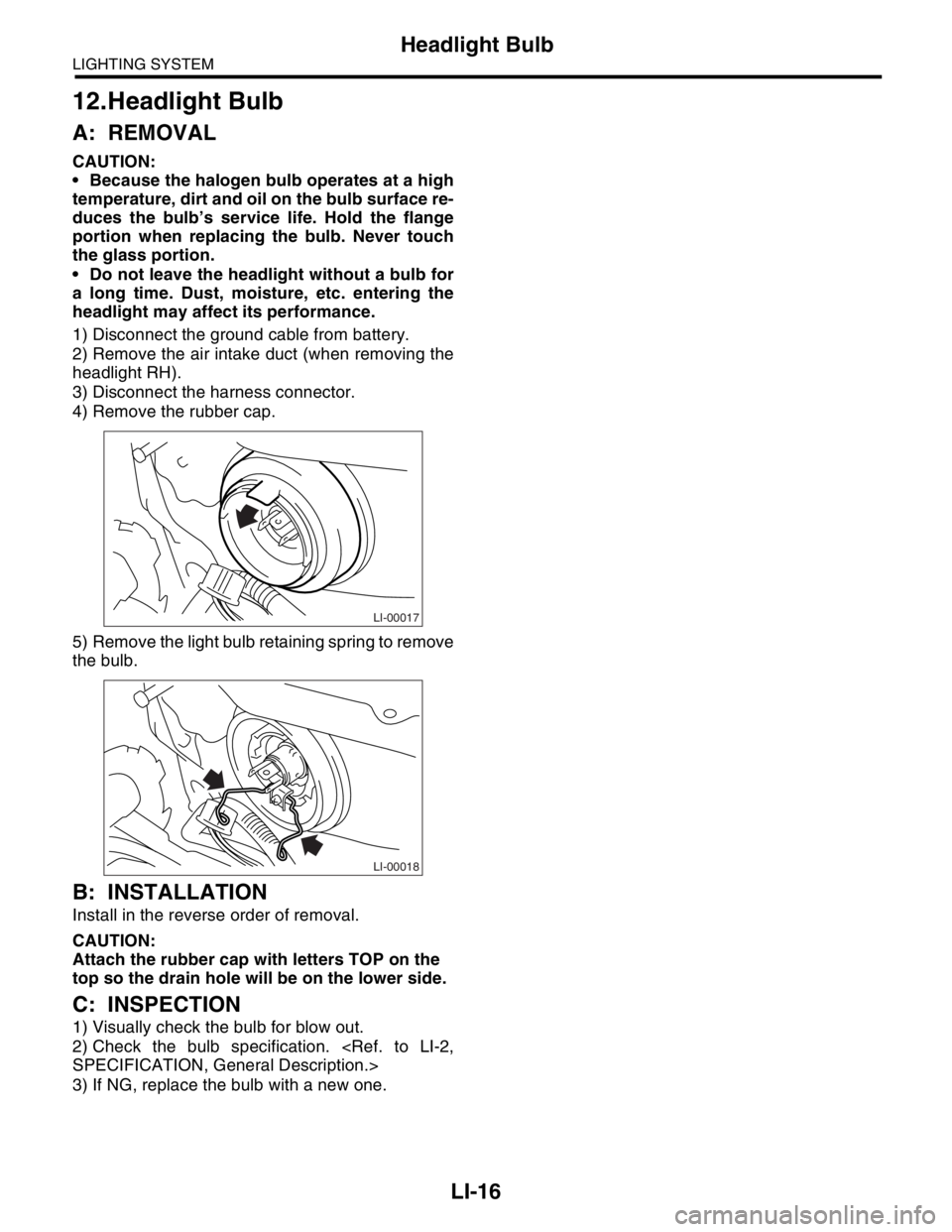
4) Remove the rubber cap.
5) Remove the light bulb retaining spring to remove
the bulb.
B: INSTALLATION
Install in the reverse order of removal.
CAUTION:
Attach the rubber cap with letters TOP on the
top so the drain hole will be on the lower side.
C: INSPECTION
1) Visually check the bulb for blow out.
2) Check the bulb specification.
SPECIFICATION, General Description.>
3) If NG, replace the bulb with a new one.
LI-00017
LI-00018
Page 313 of 2870
ET-3
ENTERTAINMENT
Radio System
2. Radio System
A: WIRING DIAGRAM
1. RADIO
B: INSPECTION
Symptom Repair order
No power coming in. (No display and no sound from speakers.) (1) Check the fuse and power supply for radio.
(2) Check the radio ground.
(3) Remove the radio for repair.
A specific speaker does not operate. (1) Check the speaker.
(2) Check the output circuit between radio and speaker.
Radio generates noise with engine running. (1) Check the radio ground.
(2) Check the generator.
(3) Check the ignition coil.
(4) Remove the radio for repair.
AM and FM modes are weak or noisy. (1) Check the antenna.
(2) Check the antenna amplifier.
(3) Check the noise suppressor.
(4) Check the radio ground.
(5) Remove the radio for repair.
Page 317 of 2870

ET-7
ENTERTAINMENT
Antenna
6. Antenna
A: INSPECTION
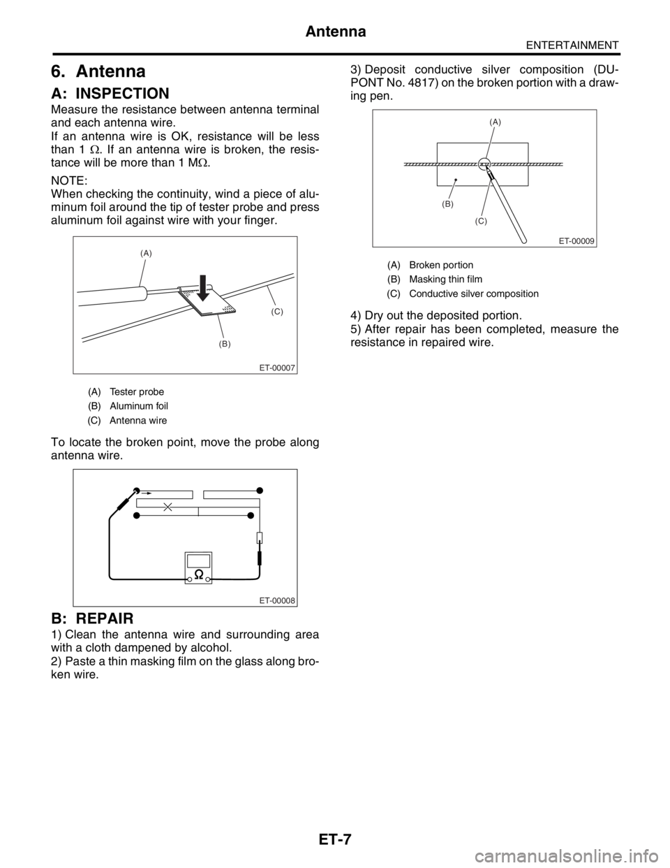
Measure the resistance between antenna terminal
and each antenna wire.
If an antenna wire is OK, resistance will be less
than 1 Ω. If an antenna wire is broken, the resis-
tance will be more than 1 MΩ.
NOTE:
When checking the continuity, wind a piece of alu-
minum foil around the tip of tester probe and press
aluminum foil against wire with your finger.
To locate the broken point, move the probe along
antenna wire.
B: REPAIR
1) Clean the antenna wire and surrounding area
with a cloth dampened by alcohol.
2) Paste a thin masking film on the glass along bro-
ken wire.3) Deposit conductive silver composition (DU-
PONT No. 4817) on the broken portion with a draw-
ing pen.
4) Dry out the deposited portion.
5) After repair has been completed, measure the
resistance in repaired wire.
(A) Tester probe
(B) Aluminum foil
(C) Antenna wire
ET-00007
(B)(C) (A)
ET-00008
(A) Broken portion
(B) Masking thin film
(C) Conductive silver composition
(B)
(C)
ET-00009
(A)
Page 361 of 2870

GW-31
GLASS/WINDOW/MIRROR
Rear Window Defogger
17.Rear Window Defogger
A: INSPECTION
CAUTION:
When wiping stain on glass off with cloth, use a
dry and soft cloth and move it in the direction of
heat wire extension to avoid damage to heat
wire.
1) Turn the ignition switch to ON.
2) Turn the defogger switch to ON.
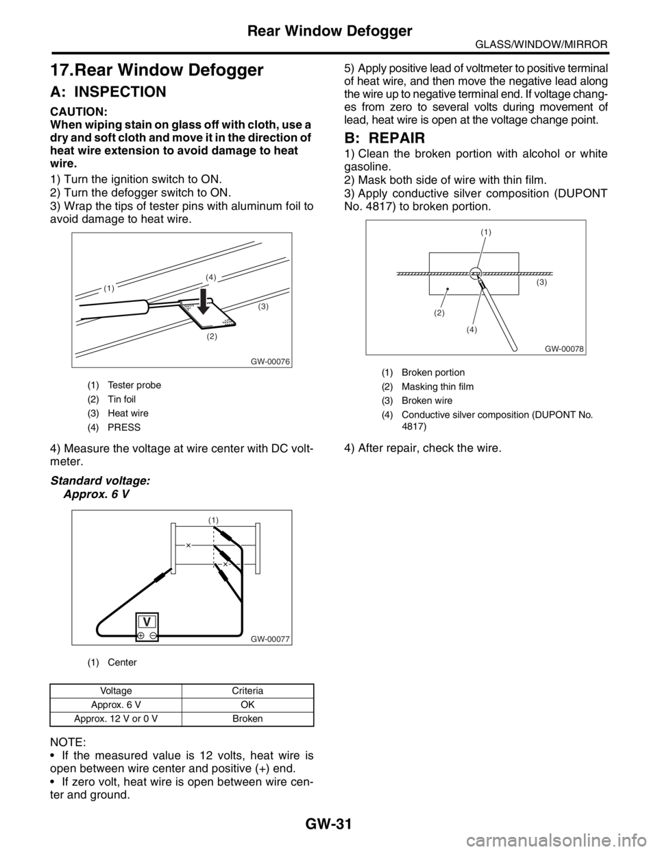
3) Wrap the tips of tester pins with aluminum foil to
avoid damage to heat wire.
4) Measure the voltage at wire center with DC volt-
meter.
Standard voltage:
Approx. 6 V
NOTE:
If the measured value is 12 volts, heat wire is
open between wire center and positive (+) end.
If zero volt, heat wire is open between wire cen-
ter and ground. 5) Apply positive lead of voltmeter to positive terminal
of heat wire, and then move the negative lead along
the wire up to negative terminal end. If voltage chang-
es from zero to several volts during movement of
lead, heat wire is open at the voltage change point.
B: REPAIR
1) Clean the broken portion with alcohol or white
gasoline.
2) Mask both side of wire with thin film.
3) Apply conductive silver composition (DUPONT
No. 4817) to broken portion.
4) After repair, check the wire.
(1) Tester probe
(2) Tin foil
(3) Heat wire
(4) PRESS
(1) Center
Voltage Criteria
Approx. 6 V OK
Approx. 12 V or 0 V Broken
GW-00076
(2)(3) (4)
(1)
GW-00077
(1)
(1) Broken portion
(2) Masking thin film
(3) Broken wire
(4) Conductive silver composition (DUPONT No.
4817)
GW-00078
(2)(3)
(4)
(1)
Page 501 of 2870

EI-25
EXTERIOR/INTERIOR TRIM
Front Bumper
C: REPAIR
1. COATING METHOD FOR PP BUMPER
Pro-
cess
No.Process name Job contents
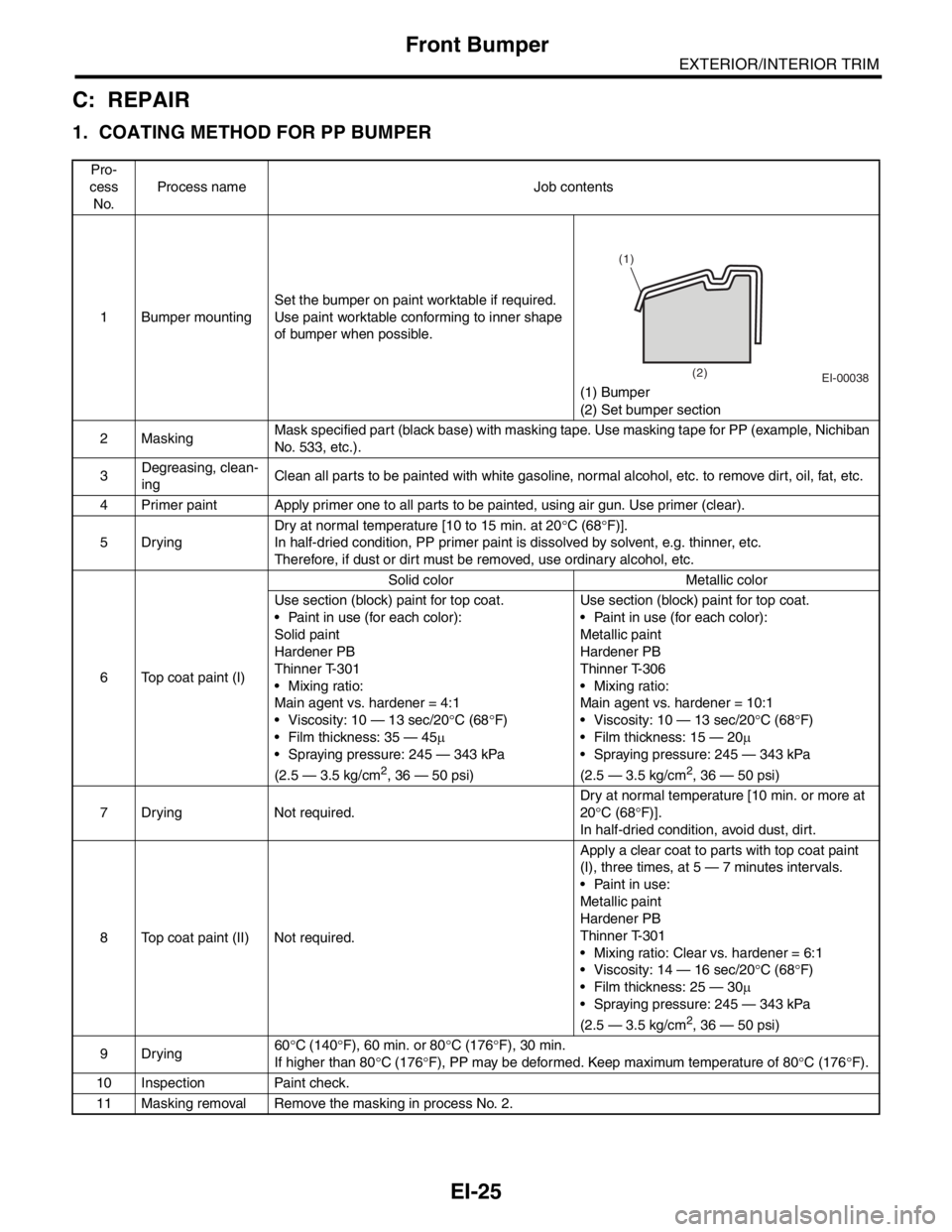
1 Bumper mountingSet the bumper on paint worktable if required.
Use paint worktable conforming to inner shape
of bumper when possible.
(1) Bumper
(2) Set bumper section
2MaskingMask specified part (black base) with masking tape. Use masking tape for PP (example, Nichiban
No. 533, etc.).
3Degreasing, clean-
ingClean all parts to be painted with white gasoline, normal alcohol, etc. to remove dirt, oil, fat, etc.
4 Primer paint Apply primer one to all parts to be painted, using air gun. Use primer (clear).
5DryingDry at normal temperature [10 to 15 min. at 20°C (68°F)].
In half-dried condition, PP primer paint is dissolved by solvent, e.g. thinner, etc.
Therefore, if dust or dirt must be removed, use ordinary alcohol, etc.
6 Top coat paint (I)Solid color Metallic color
Use section (block) paint for top coat.
Paint in use (for each color):
Solid paint
Hardener PB
Thinner T-301
Mixing ratio:
Main agent vs. hardener = 4:1
Viscosity: 10 — 13 sec/20°C (68°F)
Film thickness: 35 — 45µ
Spraying pressure: 245 — 343 kPa
(2.5 — 3.5 kg/cm
2, 36 — 50 psi)Use section (block) paint for top coat.
Paint in use (for each color):
Metallic paint
Hardener PB
Thinner T-306
Mixing ratio:
Main agent vs. hardener = 10:1
Viscosity: 10 — 13 sec/20°C (68°F)
Film thickness: 15 — 20µ
Spraying pressure: 245 — 343 kPa
(2.5 — 3.5 kg/cm2, 36 — 50 psi)
7 Drying Not required.Dry at normal temperature [10 min. or more at
20°C (68°F)].
In half-dried condition, avoid dust, dirt.
8 Top coat paint (II) Not required.Apply a clear coat to parts with top coat paint
(I), three times, at 5 — 7 minutes intervals.
Paint in use:
Metallic paint
Hardener PB
Thinner T-301
Mixing ratio: Clear vs. hardener = 6:1
Viscosity: 14 — 16 sec/20°C (68°F)
Film thickness: 25 — 30µ
Spraying pressure: 245 — 343 kPa
(2.5 — 3.5 kg/cm
2, 36 — 50 psi)
9Drying60°C (140°F), 60 min. or 80°C (176°F), 30 min.
If higher than 80°C (176°F), PP may be deformed. Keep maximum temperature of 80°C (176°F).
10 Inspection Paint check.
11 Masking removal Remove the masking in process No. 2.
EI-00038
(1)
(2)