Page 1500 of 2870
ME(H4DOTC)-42
MECHANICAL
Engine Assembly
(4) Engine harness connector
(5) Generator connector, terminal and A/C
compressor connectors
(6) Accelerator cable (2.0 L model)
(7) Clutch release spring (MT model)12) Disconnect the following hoses.
(1) Brake booster vacuum hose
(2) Heater inlet outlet hose
13) Remove the power steering pump from bracket.
(1) Loosen the lock bolt and slider bolt, and
then remove the front side V-belt.
ME(H4DOTC)-52, FRONT SIDE BELT, RE-
MOVAL, V-belt.>
(2) Disconnect the power steering switch con-
nector.
(3) Remove the pipe with bracket from intake
manifold.
(A) A/C compressor connector
(B) Generator connector and terminal
ME-00029
ME-00030
(A) (B)
ME-00031
ME-00032
ME-00033
ME-00035
ME-00036
Page 1501 of 2870
ME(H4DOTC)-43
MECHANICAL
Engine Assembly
(4) Remove the power steering pump from en-
gine.
(5) Remove the reservoir tank from bracket by
pulling it upward.
(6) Place the power steering pump on RH side
wheel apron.
14) Lift-up the vehicle.
15) Remove the ATF cooler pipe from frame. (AT
model)
16) Remove the center exhaust pipe.
EX(H4DOTC)-9, REMOVAL, Center Exhaust
Pipe.>17) Remove the nuts which hold the lower side of
transmission to engine.
18) Remove the nuts which install the front cushion
rubber onto front crossmember.
19) Lower the vehicle.
20) Separate the clutch release fork from release
bearing. (MT model)
(1) Remove the clutch operating cylinder from
transmission.
(2) Remove the plug using a 10 mm hexagon
wrench.
ME-00037
ME-00038
ME-00039ME-00040
ME-00041
ME-00042
Page 1505 of 2870

ME(H4DOTC)-47
MECHANICAL
Engine Assembly
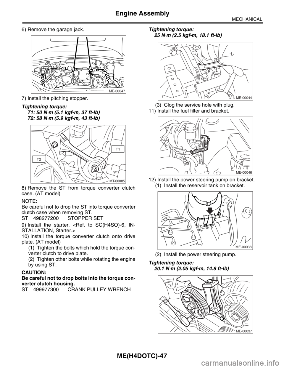
6) Remove the garage jack.
7) Install the pitching stopper.
Tightening torque:
T1: 50 N
⋅m (5.1 kgf-m, 37 ft-lb)
T2: 58 N
⋅m (5.9 kgf-m, 43 ft-lb)
8) Remove the ST from torque converter clutch
case. (AT model)
NOTE:
Be careful not to drop the ST into torque converter
clutch case when removing ST.
ST 498277200 STOPPER SET
9) Install the starter.
STALLATION, Starter.>
10) Install the torque converter clutch onto drive
plate. (AT model)
(1) Tighten the bolts which hold the torque con-
verter clutch to drive plate.
(2) Tighten other bolts while rotating the engine
by using ST.
CAUTION:
Be careful not to drop bolts into the torque con-
verter clutch housing.
ST 499977300 CRANK PULLEY WRENCHTightening torque:
25 N
⋅m (2.5 kgf-m, 18.1 ft-lb)
(3) Clog the service hole with plug.
11) Install the fuel filter and bracket.
12) Install the power steering pump on bracket.
(1) Install the reservoir tank on bracket.
(2) Install the power steering pump.
Tightening torque:
20.1 N
⋅m (2.05 kgf-m, 14.8 ft-lb)
ME-00047
T1
T2
MT-00085ME-00044
ME-00046
ME-00038
ME-00037
Page 1506 of 2870

ME(H4DOTC)-48
MECHANICAL
Engine Assembly
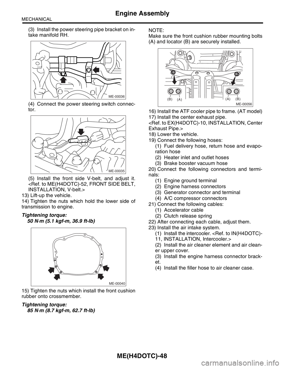
(3) Install the power steering pipe bracket on in-
take manifold RH.
(4) Connect the power steering switch connec-
tor.
(5) Install the front side V-belt, and adjust it.
INSTALLATION, V-belt.>
13) Lift-up the vehicle.
14) Tighten the nuts which hold the lower side of
transmission to engine.
Tightening torque:
50 N
⋅m (5.1 kgf-m, 36.9 ft-lb)
15) Tighten the nuts which install the front cushion
rubber onto crossmember.
Tightening torque:
85 N
⋅m (8.7 kgf-m, 62.7 ft-lb)NOTE:
Make sure the front cushion rubber mounting bolts
(A) and locator (B) are securely installed.
16) Install the ATF cooler pipe to frame. (AT model)
17) Install the center exhaust pipe.
Exhaust Pipe.>
18) Lower the vehicle.
19) Connect the following hoses:
(1) Fuel delivery hose, return hose and evapo-
ration hose
(2) Heater inlet and outlet hoses
(3) Brake booster vacuum hose
20) Connect the following connectors and termi-
nals:
(1) Engine ground terminal
(2) Engine harness connectors
(3) Generator connector and terminal
(4) A/C compressor connectors
21) Connect the following cables:
(1) Accelerator cable
(2) Clutch release spring
22) After connecting each cable, adjust them.
23) Install the air intake system.
(1) Install the intercooler.
11, INSTALLATION, Intercooler.>
(2) Install the air cleaner element and air clean-
er upper cover.
(3) Install the engine harness connector brack-
et.
(4) Install the filler hose to air cleaner case.
ME-00036
ME-00035
ME-00040
ME-00056
(A)
(A)(B)
(B)
Page 1511 of 2870
ME(H4DOTC)-53
MECHANICAL
V-belt
2. REAR SIDE BELT
1) Install the belt, and tighten the slider bolt (B) so
as to obtain the specified belt tension.
ME(H4DOTC)-53, INSPECTION, V-belt.>
2) Tighten the lock nut (A).
Tightening torque:
Lock nut (A);
22.6 N
⋅m (2.3 kgf-m, 16.6 ft-lb)
C: INSPECTION
1) Replace the belts, if cracks, fraying or wear is
found.
2) Check the drive belt tension and adjust it if nec-
essary by changing generator installing position
and/or idler pulley installing position.
Belt tension (With using belt tension gauge)
(A)
Replaced: 640 — 780 N (65 — 80 kgf, 144 —
175 lb)
Reused: 490 — 640 N (50 — 65 kgf, 110 — 144
lb)
(B)*
Replaced: 740 — 880 N (76 — 89 kgf, 167 —
197 lb)
Reused: 350 — 450 N (36 — 46 kgf, 78 — 101
lb)
*: With air conditioner
(A)
(B)
ME-00060
(A) Front side belt
(B) Rear side belt
C/P Crank pulley
GEN Generator
P/S Power steering oil pump pulley
A/C A/C compressor pulley
I/P Idler pulley
C/P P/SA/C
GEN
(A)
(B)
I/P
PM-00154
Page 1512 of 2870
ME(H4DOTC)-54
MECHANICAL
V-belt
Belt tension (Without using belt tension gauge)
(A)
Replaced: 7 — 9 mm (0.276 — 0.354 in)
Reused: 9 — 11 mm (0.354 — 0.433 in)
(B)*
Replaced: 7.5 — 8.5 mm (0.295 — 0.335 in)
Reused: 9.0 — 10.0 mm (0.354 — 0.394 in)
*: With air conditioner
(A) Front side belt
(B) Rear side belt
C/P Crank pulley
GEN Generator
P/S Power steering oil pump pulley
A/C Air conditioning compressor pulley
I/P Idler pulley
ME-00062
P/S
C/PGEN
I/P A/C 98 N (10 kgf, 22 lb)
(A)(B)
Page 1598 of 2870

EX(H4DOTC)-12
EXHAUST
Center Exhaust Pipe
12) Place the turbocharger upper cover, and tight-
en the bolts which install upper side of upper cover.
Tightening torque:
7.4 N·m (0.75 kgf-m, 5.4 ft-lb)
13) Lift-up the vehicle.
14) Tighten the bolts which install under side of tur-
bocharger upper cover.
Tightening torque:
7.4 N·m (0.75 kgf-m, 5.4 ft-lb)
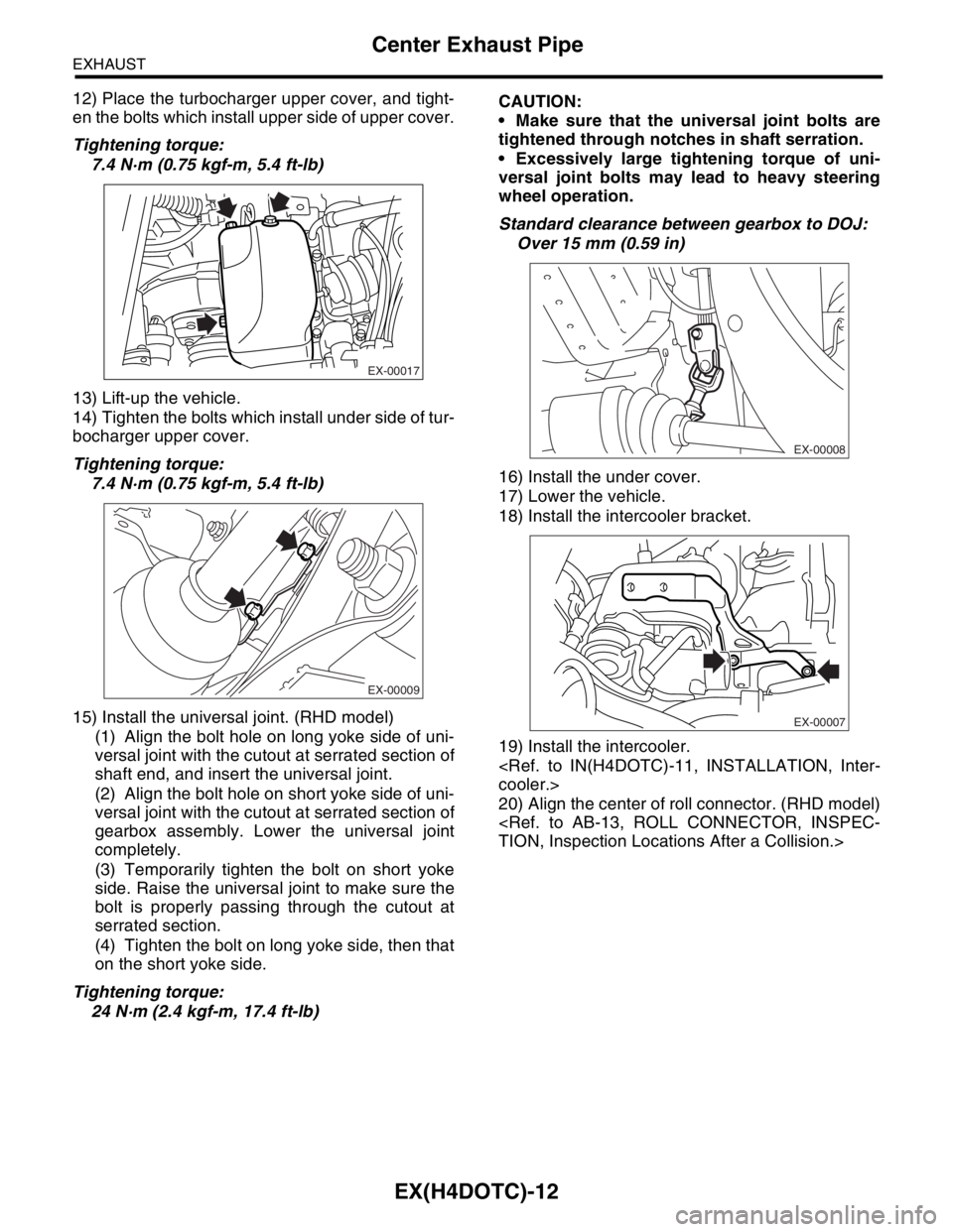
15) Install the universal joint. (RHD model)
(1) Align the bolt hole on long yoke side of uni-
versal joint with the cutout at serrated section of
shaft end, and insert the universal joint.
(2) Align the bolt hole on short yoke side of uni-
versal joint with the cutout at serrated section of
gearbox assembly. Lower the universal joint
completely.
(3) Temporarily tighten the bolt on short yoke
side. Raise the universal joint to make sure the
bolt is properly passing through the cutout at
serrated section.
(4) Tighten the bolt on long yoke side, then that
on the short yoke side.
Tightening torque:
24 N·m (2.4 kgf-m, 17.4 ft-lb)CAUTION:
Make sure that the universal joint bolts are
tightened through notches in shaft serration.
Excessively large tightening torque of uni-
versal joint bolts may lead to heavy steering
wheel operation.
Standard clearance between gearbox to DOJ:
Over 15 mm (0.59 in)
16) Install the under cover.
17) Lower the vehicle.
18) Install the intercooler bracket.
19) Install the intercooler.
cooler.>
20) Align the center of roll connector. (RHD model)
TION, Inspection Locations After a Collision.>
EX-00017
EX-00009
EX-00008
EX-00007
Page 1637 of 2870

EN(H4DOTC)-7
ENGINE (DIAGNOSTIC)
General Description
12) Observe the following cautions when installing
a radio in MFI equipped models.
CAUTION:
The antenna must be kept as far apart as pos-
sible from the control unit. (The ECM is located
under the steering column, inside of the instru-
ment panel lower trim panel.)
The antenna feeder must be placed as far
apart as possible from the ECM and MFI har-
ness.
Carefully adjust the antenna for correct
matching.
When mounting a large power type radio, pay
special attention to the three items above men-
tioned.
Incorrect installation of the radio may affect
the operation of the ECM.
13) Before disconnecting the fuel hose, disconnect
the fuel pump connector and crank the engine for
more than five seconds to release pressure in the
fuel system.If engine starts during this operation,
run it until it stops.
14) Problems in the electronic-controlled automatic
transmission may be caused by failure of the en-
gine, the electronic control system, the transmis-
sion proper, or by a combination of these.These
three causes (engine, electronic control system,
transmission) must be distinguished clearly when
performing diagnostics.
15) Diagnostics should be conducted by rotating
with simple, easy operations and proceeding to
complicated, difficult operations.The most impor-
tant thing in diagnostics is to understand the cus-
tomer’s complaint, and distinguish between the
three causes.
16) On the model with ABS, when performing driv-
ing test in jacked-up or lifted-up position, some-
times the warning light may be lit, but this is not a
malfunction of the system.The reason for this is the
speed difference between the front and rear
wheels.After diagnosis of engine control system,
perform the ABS memory clearance procedure of
self-diagnosis function.
B: INSPECTION
Before performing diagnostics, check the following
items which might affect engine problems:
1. BATTERY
1) Measure battery voltage and specific gravity of
electrolyte.
Standard voltage: 12 V
Specific gravity: Above 1.2602) Check the condition of the main and other fuses,
and harnesses and connectors.Also check for
proper grounding.
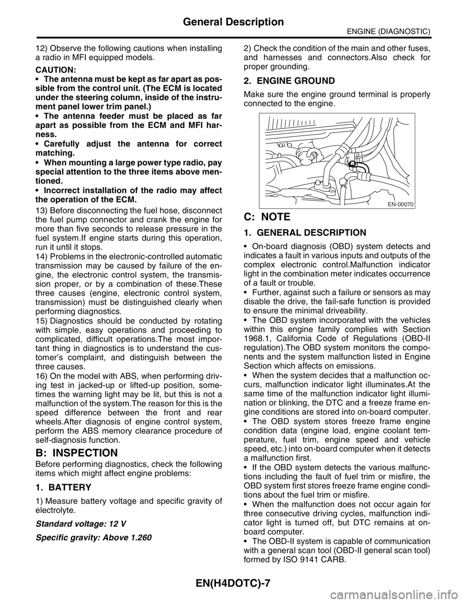
2. ENGINE GROUND
Make sure the engine ground terminal is properly
connected to the engine.
C: NOTE
1. GENERAL DESCRIPTION
On-board diagnosis (OBD) system detects and
indicates a fault in various inputs and outputs of the
complex electronic control.Malfunction indicator
light in the combination meter indicates occurrence
of a fault or trouble.
Further, against such a failure or sensors as may
disable the drive, the fail-safe function is provided
to ensure the minimal driveability.
The OBD system incorporated with the vehicles
within this engine family complies with Section
1968.1, California Code of Regulations (OBD-II
regulation).The OBD system monitors the compo-
nents and the system malfunction listed in Engine
Section which affects on emissions.
When the system decides that a malfunction oc-
curs, malfunction indicator light illuminates.At the
same time of the malfunction indicator light illumi-
nation or blinking, the DTC and a freeze frame en-
gine conditions are stored into on-board computer.
The OBD system stores freeze frame engine
condition data (engine load, engine coolant tem-
perature, fuel trim, engine speed and vehicle
speed, etc.) into on-board computer when it detects
a malfunction first.
If the OBD system detects the various malfunc-
tions including the fault of fuel trim or misfire, the
OBD system first stores freeze frame engine condi-
tions about the fuel trim or misfire.
When the malfunction does not occur again for
three consecutive driving cycles, malfunction indi-
cator light is turned off, but DTC remains at on-
board computer.
The OBD-II system is capable of communication
with a general scan tool (OBD-II general scan tool)
formed by ISO 9141 CARB.
EN-00070