Page 781 of 2870
PM-44
PERIODIC MAINTENANCE SERVICE
Steering System (Power Steering)
Page 796 of 2870

FU(H4SO)-14
FUEL INJECTION (FUEL SYSTEM)
Intake Manifold
3. Intake Manifold
A: REMOVAL
1) Release the fuel pressure.
47, RELEASING OF FUEL PRESSURE, OPERA-
TION, Fuel.>
2) Open the fuel flap lid, and remove the fuel filler
cap.
3) Disconnect the ground cable from battery.
4) Remove the air intake duct and air cleaner case.
Case.>
5) Disconnect the accelerator cable (A).
6) Disconnect the cruise control cable (B). (With
cruise control model)
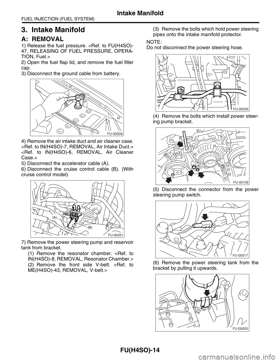
7) Remove the power steering pump and reservoir
tank from bracket.
(1) Remove the resonator chamber.
IN(H4SO)-8, REMOVAL, Resonator Chamber.>
(2) Remove the front side V-belt.
ME(H4SO)-43, REMOVAL, V-belt.>(3) Remove the bolts which hold power steering
pipes onto the intake manifold protector.
NOTE:
Do not disconnect the power steering hose.
(4) Remove the bolts which install power steer-
ing pump bracket.
(5) Disconnect the connector from the power
steering pump switch.
(6) Remove the power steering tank from the
bracket by pulling it upwards.
FU-00009
FU-00251
(B)
(A)
FU-00255
FU-00139
FU-00017
FU-00020
Page 797 of 2870
FU(H4SO)-15
FUEL INJECTION (FUEL SYSTEM)
Intake Manifold
(7) Place the power steering pump on the right
side wheel apron.
8) Disconnect the spark plug cords from the spark
plugs.
9) Disconnect the PCV hose from the intake mani-
fold.
10) Disconnect the engine coolant hose (A) from
the throttle body.
11) Disconnect the brake booster hose.12) Remove the air cleaner case stay RH and en-
gine harness bracket, and disconnect the engine
harness connectors from the bulkhead harness
connectors.
13) Disconnect the connectors from the engine
coolant temperature sensor.
14) Disconnect the knock sensor connector.
15) Disconnect the connector from the crankshaft
position sensor.
FU-00021
FU-00141
FU-00361
(A)(A)
FU-00143
FU-00258
FU-00145
FU-00062
FU-00056
Page 800 of 2870
FU(H4SO)-18
FUEL INJECTION (FUEL SYSTEM)
Intake Manifold
10) Connect the brake booster hose.
11) Connect the engine coolant hose (A) to the
throttle body.
12) Connect the PCV hose to the intake manifold.
13) Connect the spark plug cords to the spark
plugs.
14) Install the power steering pump and reservoir
tank to bracket.
(1) Install the reservoir tank to bracket.(2) Connect the connector to the power steering
pump switch.
(3) Tighten the bolts which install power steer-
ing pump bracket.
Tightening torque:
22 N
⋅m (2.2 kgf-m, 15.9 ft-lb)
(4) Install the power steering pipes onto the
right side intake manifold protector.
(5) Install the front side V-belt.
ME(H4SO)-43, INSTALLATION, V-belt.>
FU-00143
FU-00361
(A)(A)
FU-00141
FU-00020
FU-00017
FU-00139
FU-00255
Page 817 of 2870
FU(H4SO)-35
FUEL INJECTION (FUEL SYSTEM)
Fuel Injector
13.Fuel Injector
A: REMOVAL
1. RH SIDE
1) Release the fuel pressure.
PRESSURE, OPERATION, Fuel.>
2) Open the fuel flap lid, and remove the fuel filler
cap.
3) Disconnect the ground cable from battery.
4) Remove the resonator chamber.
IN(H4SO)-8, REMOVAL, Resonator Chamber.>
5) Remove the spark plug cords from the spark
plugs (#1 and #3 cylinders).6) Remove the power steering pump and reservoir
tank from the brackets.
(1) Remove the front side V-belt.
ME(H4SO)-43, REMOVAL, V-belt.>
(2) Remove the bolts which hold the power
steering pipes onto the intake manifold protec-
tor.
(3) Remove the bolts which install the power
steering pump to the bracket.
(4) Disconnect the connector from the power
steering pump switch.
FU-00009
FU-00302
FU-00255
FU-00139
FU-00017
Page 818 of 2870
FU(H4SO)-36
FUEL INJECTION (FUEL SYSTEM)
Fuel Injector
(5) Remove the power steering tank from the
bracket by pulling it upwards.
(6) Place the power steering pump and reser-
voir tank on the right side wheel apron.
7) Remove the fuel pipe protector RH.
8) Disconnect the connector from fuel injector.9) Remove the bolts which holds the fuel injector
pipe to the intake manifold.
10) Remove the fuel injector from the intake mani-
fold.
(1) Remove the fuel injector securing clip.
(2) Remove the fuel injector while lifting up the
fuel injector pipe.
FU-00020
FU-00021
FU-00267
FU-00303
FU-00284
FU-00304
FU-00305
FU-00306
Page 904 of 2870
ME(H4SO)-35
MECHANICAL
Engine Assembly
(4) Engine harness connectors
(5) Generator connector, terminal and A/C
compressor connector
(6) Accelerator cable (A) and cruise control ca-
ble (B)(7) Pressure switch
12) Disconnect the following hoses.
(1) Brake booster vacuum hose
(2) Heater inlet and outlet hose
(3) Heater inlet and outlet hose (with ATF
warmer model)
13) Remove the power steering pump from brack-
et.
(1) Remove the resonator chamber.
(A) Generator connector and terminal
(B) A/C compressor connector
ME-00207
ME-00208
(A)
(B)
(B)(A)
ME-00328
FU-00017
ME-00329
ME-00330
ME-02009
Page 905 of 2870
ME(H4SO)-36
MECHANICAL
Engine Assembly
(2) Loosen the lock bolt and slider bolt, and
then remove the front side V-belt.
ME(H4SO)-43, FRONT SIDE BELT, REMOV-
AL, V-belt.>
(3) Remove the pipe with bracket.
(4) Remove the bolts which install power steer-
ing pump bracket.
(5) Remove the reservoir tank from bracket by
pulling it upward.
(6) Place the power steering pump on right side
wheel apron.14) Remove the front and center exhaust pipe.
Pipe.>
15) Remove the nuts which hold lower side of
transmission to engine.
16) Remove the nuts which install front cushion
rubber onto front crossmember.
17) Separate the torque converter clutch from drive
plate. (AT model)
(1) Lower the vehicle.
(2) Remove the service hole plug.
(3) Remove the bolts which hold torque con-
verter clutch to drive plate.
(4) Remove other bolts while rotating the en-
gine using socket wrench.
ME-00331
FU-00139
FU-00020
FU-00140ME-00210
ME-00211
ME-00212