Page 455 of 2870
SL-35
SECURITY AND LOCK
Ignition Key Lock
17.Ignition Key Lock
A: REPLACEMENT
1) Remove the ground cable from battery.
2) Remove the steering column.
REMOVAL, Tilt Steering Column.>
3) Secure the steering column in a vise. Remove
the bolt with a drill.
4) Remove the ignition key lock.
5) Use a new torn bolt. Tighten the torn bolt to end
of thread.
B: INSPECTION
1) Remove the instrument panel lower cover.
2) Remove the lower column cover.
3) Unfasten the holddown clip which secures harness
and disconnect the connector of ignition switch from
body harness.
4) Turn the ignition key plate to each position and
check the continuity between terminals of ignition
connector.
If NG, replace the ignition switch.
Switch position Terminal No. Standard
LOCK — —
ACC No. 1 and No. 2 Less than 1 Ω
ON No. 1 and No. 2
No. 1 and No. 4
No. 2 and No. 4Less than 1 Ω
ST No. 1 and No. 3
No. 1 and No. 4
No. 3 and No. 4Less than 1 Ω
SL-00024
SL-00025
Page 488 of 2870
EI-12
EXTERIOR/INTERIOR TRIM
General Description
14.INSTRUMENT PANEL
LHD MODEL
(1) Pad & frame (7) Center panel (13) Grille cover
(2) Center compartment (8) Air vent grille (14) Air vent grille (Defroster)
(3) Grille cover (9) Cup holder (15) Switch panel
(4) Lower cover (10) Glove box panel (16) Passenger’s airbag module
(5) Coin box (11) Glove box lid
(6) Meter visor (12) Steering beam
EI-00793
(9)
(14)
(16)
(4)
(3)
(2)
(13)
(12)
(11) (15)
(1)
(8)
(10)
(5)
(6)
(7)
A
A
Page 489 of 2870
EI-13
EXTERIOR/INTERIOR TRIM
General Description
RHD MODEL
(1) Pad & frame (7) Center panel (13) Grille cover
(2) Center compartment (8) Air vent grille (14) Air vent grille (Defroster)
(3) Grille cover (9) Cup holder (15) Switch panel
(4) Lower cover (10) Glove box panel (16) Passenger’s airbag module
(5) Coin box (11) Glove box lid
(6) Meter cover (12) Steering beam
EI-00226
(12)
(14)
(3)
(2)
(11)
(10)
(9)(13)
(1)
(7)
(8)
(15)(4)
(5)
(6)A
A
(16)
Page 517 of 2870

EI-41
EXTERIOR/INTERIOR TRIM
Instrument Panel Assembly
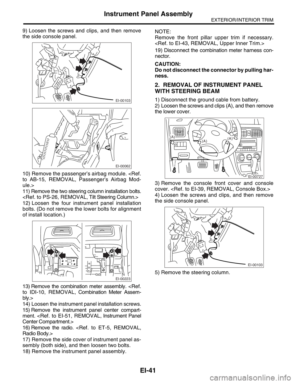
9) Loosen the screws and clips, and then remove
the side console panel.
10) Remove the passenger’s airbag module.
to AB-15, REMOVAL, Passenger’s Airbag Mod-
ule.>
11) Remove the two steering column installation bolts.
12) Loosen the four instrument panel installation
bolts. (Do not remove the lower bolts for alignment
of install location.)
13) Remove the combination meter assembly.
to IDI-10, REMOVAL, Combination Meter Assem-
bly.>
14) Loosen the instrument panel installation screws.
15) Remove the instrument panel center compart-
ment.
Center Compartment.>
16) Remove the radio.
Radio Body.>
17) Remove the side cover of instrument panel as-
sembly (both side), and then loosen two bolts.
18) Remove the instrument panel assembly.NOTE:
Remove the front pillar upper trim if necessary.
19) Disconnect the combination meter harness con-
nector.
CAUTION:
Do not disconnect the connector by pulling har-
ness.
2. REMOVAL OF INSTRUMENT PANEL
WITH STEERING BEAM
1) Disconnect the ground cable from battery.
2) Loosen the screws and clips (A), and then remove
the lower cover.
3) Remove the console front cover and console
cover.
4) Loosen the screws and clips, and then remove
the side console panel.
5) Remove the steering column.EI-00103
EI-00062
EI-00223
EI-00727
(A)
(A)(A)
EI-00103
Page 518 of 2870
EI-42
EXTERIOR/INTERIOR TRIM
Instrument Panel Assembly
6) Loosen the four instrument panel installation bolts.
7) Remove the driver’s and passenger’s airbag mod-
ule.
Module.>
Airbag Module.>
8) Loosen the steering beam installation bolts.
9) Loosen the brake pedal installation bolts.
to BR-50, REMOVAL, Brake Pedal.>
10) Remove two clips from the edge of instrument
panel assembly.
11) Remove the instrument panel assembly.
CAUTION:
Do not disconnect the connector by pulling har-
ness.
NOTE:
If necessary, make matching marks for easy re-
assembly.
When storing the removed instrument panel, place it
standing up on the floor.B: INSTALLATION
Install in the reverse order of removal.
CAUTION:
Be careful not to snag the harness.
Make sure to connect the harness connector.
NOTE:
When setting the instrument panel into position, push
the hook into grommet (A) on the body panel.
EI-00066
EI-00068
EI-00069
(A)
(A)(A)
Page 561 of 2870

CC-9
CRUISE CONTROL SYSTEM
Cruise Control Command Switch
5. Cruise Control Command
Switch
A: REMOVAL
WARNING:
Before servicing, be sure to read the notes in
the AB section for proper handling of the driv-
er’s airbag module.
General Description.>
1) Set the front wheels in straight ahead position.
2) Turn the ignition switch to OFF.
3) Disconnect the ground cable from battery and
wait for at least 20 seconds before starting work.
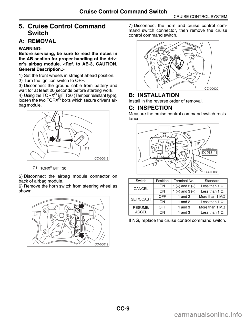
4) Using the TORX
® BIT T30 (Tamper resistant type),
loosen the two TORX® bolts which secure driver’s air-
bag module.
5) Disconnect the airbag module connector on
back of airbag module.
6) Remove the horn switch from steering wheel as
shown.7) Disconnect the horn and cruise control com-
mand switch connector, then remove the cruise
control command switch.
B: INSTALLATION
Install in the reverse order of removal.
C: INSPECTION
Measure the cruise control command switch resis-
tance.
If NG, replace the cruise control command switch.
(1)
TORX® BIT T30
CC-00018
(1)
CC-00019
Switch Position Terminal No. Standard
CANCELON 1 (+) and 2 (−) Less than 1 Ω
ON 1 (+) and 3 (−) Less than 1 Ω
SET/COASTOFF 1 and 2 More than 1 MΩ
ON 1 and 2 Less than 1 Ω
RESUME/
ACCELOFF 1 and 3 More than 1 MΩ
ON 1 and 3 Less than 1 Ω
CC-00020
CC-00038
1 2 3
Page 587 of 2870
CC(H4SO)-19
CRUISE CONTROL SYSTEM (DIAGNOSTIC)
Diagnostic Procedure with Symptom
E: CHECK CRUISE CONTROL COMMAND SWITCH
TROUBLE SYMPTOM:
Cruise control cannot be set. (Cancelled immediately.)
WIRING DIAGRAM:
CC-00040
B94F45B236S1F144
12345678910
11 12 13 14 15 16 17 18 19 20
412365
4
321
BATTERY
CRUISE CONTROL MODULECRUISE CONTROL
COMMAND SWITCH
STEERING
ROLL CONNECTORHORN HORN RELAY HORN SWITCH
RESUME/
ACCEL
SWITCHCANCEL
SWITCHSET/
COAST
SWITCH M/B No.6
B94
F37
B62F45
S1
321
910
B236
13
3 2
11
3245123
8910411 12 13 14 15 16567
F144
F37
RHD
RHD
LHD
LHD
RHD :
:LHD
: LHD MODEL
: RHD MODEL
LHD
RHDRHD LHD
RHD :
:LHD
Page 665 of 2870

FUJI HEAVY INDUSTRIES LTD. G8080GE6
2004 FORESTER SERVICE MANUAL QUICK REFERENCE INDEX
CHASSIS SECTION
This service manual has been prepared
to provide SUBARU service personnel
with the necessary information and data
for the correct maintenance and repair
of SUBARU vehicles.
This manual includes the procedures
for maintenance, disassembling, reas-
sembling, inspection and adjustment of
components and diagnostics for guid-
ance of experienced mechanics.
Please peruse and utilize this manual
fully to ensure complete repair work for
satisfying our customers by keeping
their vehicle in optimum condition.
When replacement of parts during
repair work is needed, be sure to use
SUBARU genuine parts.
All information, illustration and specifi-
cations contained in this manual are
based on the latest product information
available at the time of publication
approval.FRONT SUSPENSION FS
REAR SUSPENSION RS
WHEEL AND TIRE SYSTEM WT
DIFFERENTIAL DI
TRANSFER CASE TC
DRIVE SHAFT SYSTEM DS
ABS ABS
ABS (DIAGNOSTIC) ABS
BRAKE BR
PARKING BRAKE PB
POWER ASSISTED SYSTEM
(POWER STEERING)PS