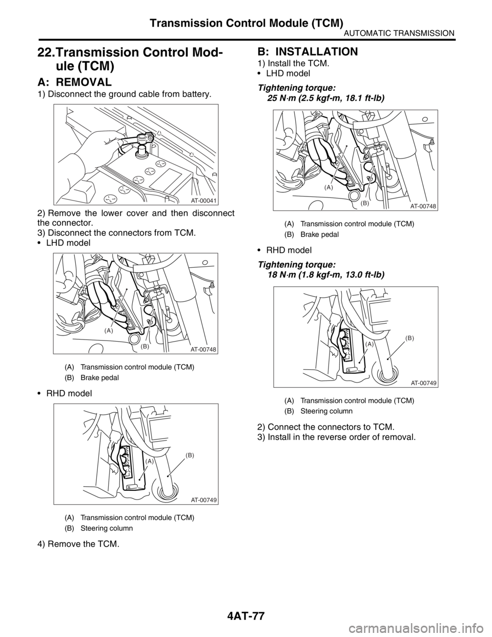
2004 SUBARU FORESTER steering
[x] Cancel search: steeringPage 2043 of 2870

EN(H4DOTC 2.5)-19
ENGINE (DIAGNOSTIC)
Engine Control Module (ECM) I/O Signal
Radiator fan relay 2 con-
trolB135 24ON: 0.5, or less
OFF: 10 — 13ON: 0.5, or less
OFF: 13 — 14Model with A/C only
Malfunction indicator
lightB134 17 — —Light “ON”: 1, or less
Light “OFF”: 10 — 14
Engine speed output B134 23 — 0 — 13, or more Waveform
Purge control solenoid
valveB134 14ON: 1, or less
OFF: 10 — 13ON: 1, or less
OFF: 13 — 14Wavefor m
Manifold
absolute
pressure
sensorSignal B136 22 1.7 — 2.4 1.1 — 1.6
— Pow er
supplyB136 16 5 5
GND
(sensors)B136 35 0 0
Small light switch B137 12ON: 0
OFF: 10 — 13ON: 0
OFF: 13 — 14—
Blower fan switch B137 13ON: 0
OFF: 10 — 13ON: 0
OFF: 13 — 14—
Rear defogger switch B137 11ON: 0
OFF: 10 — 13ON: 0
OFF: 13 — 14—
Power steering oil pres-
sure switchB137 10 10 — 13ON: 0
OFF: 13 — 14—
Front oxygen (A/F) sen-
sor signal (+)B134 33 2.8 — 3.2 2.8 — 3.2 —
Front oxygen (A/F) sen-
sor signal (−)B134 26 2.4 — 2.7 2.4 — 2.7 —
Front oxygen (A/F) sen-
sor shieldB134 25 0 0 —
SSM/GST communica-
tion lineB137 20 1 ← → 41 ← → 4—
GND (injector) B137 7 0 0 —
GND (ignition system) B135 12 0 0 —
GND (power supply)B135 4 0 0 —
B135 1 0 0 —
GND (control system)B137 1 0 0 —
B137 2 0 0 —
GND (Front oxygen (A/F)
sensor heater 1)B134 7 0 0 —
GND (Front oxygen (A/F)
sensor heater 2)B134 6 0 0 —
Camshaft position sen-
sor (LH)B135 8 0 — 0.9ON: 0
OFF: 4.7 — 5.3Wavefor m
Camshaft position sen-
sor (RH)B135 9 0 — 0.9ON: 0
OFF: 4.7 — 5.3Wavefor m
Fuel level sensor B136 20 0.12 — 4.75 0.12 — 4.75 —
Electronic
throttle
controlMain B136 180.64 — 0.72
Fully opens:
3.960.64 — 0.72
(After engine is
warmed-up.)Fully closed: 0.6 Fully opens:
3.96
Sub B136 291.51 — 1.58
Fully opens:
4.171.51 — 1.58
(After engine is
warmed-up)Fully closed: 1.48 Fully opens:
4.17
Pow er
supplyB136 16 5 5 —
GND
(sensor)B137 3 0 0 — DESCRIPTION Connector No. Terminal No.Signal (V)
NOTE
Ignition SW ON
(engine OFF)Engine ON
(Idling)
Page 2053 of 2870

EN(H4DOTC 2.5)-29
ENGINE (DIAGNOSTIC)
Subaru Select Monitor
NOTE:
For detailed operation procedure, refer to the “SUBARU SELECT MONITOR OPERATION MANUAL”.
Mass air flow sensor signal Air Flow Sensor Voltage V
AT/MT identification signal AT Vehicle ID Signal ON or OFF
ETC motor relay ETC Motor Relay ON or OFF
Clutch SW Clutch Switch ON or OFF
Stop Light SW Stop Light Switch ON or OFF
SET/COAST SW SET/COAST Switch ON or OFF
RESUME/ACCEL SW RESUME/ACCEL Switch ON or OFF
Brake SW Brake Switch ON or OFF
Main SW Main Switch ON or OFF
Ignition switch signal Ignition Switch ON or OFF
Test Mode Signal Test Mode Signal ON or OFF
Neutral position switch signal Neutral Position Switch ON or OFF
Air conditioning switch signal A/C Switch ON or OFF
Air conditioning signal A/C Compressor Signal ON or OFF
Radiator main fan relay signal Radiator Fan Relay #1 ON or OFF
Knocking signal Knocking Signal ON or OFF
Radiator sub fan relay signal Radiator Fan Relay #2 ON or OFF
Power steering switch signal P/S Switch ON or OFF
Rear oxygen sensor rich signalRear O
2 Rich Signal
ON or OFF
Starter switch signal Starter Switch ON or OFF
Idle switch signal Idle Switch Signal ON or OFF
Crankshaft position sensor signal Crankshaft Position Sig. ON or OFF
Camshaft position sensor signal Camshaft Position Sig. ON or OFF
Rear defogger switch signal Rear Defogger SW ON or OFF
Blower fan switch signal Blower Fan SW ON or OFF
Small light switch signal Light Switch ON or OFF
Handle switch signal Handle Switch —
Wiper switch signal Wiper Switch ON or OFF
A/C mid pressure switch signal A/C mid Pressure Switch ON or OFF
AT coordinate retard angle demand Retard Signal form AT ON or OFF
AT coordinate fuel cut demand Fuel Cut Signal from AT ON or OFF
AT coordinate permission signal Torque Permission Signal ON or OFF
UDC not torque down output Ban of Torque Down ON or OFF
UDC torque down demand Request Torque Down UDC ON or OFF
Tumble generated valve output signal TGV Output ON or OFF
Tumble generated valve drive signal TGV Drive OPEN or CLOSERemarks Display Unit of measure
Page 2056 of 2870
![SUBARU FORESTER 2004 Service Repair Manual EN(H4DOTC 2.5)-32
ENGINE (DIAGNOSTIC)
Subaru Select Monitor
7. LED OPERATION MODE FOR ENGINE
1) On the «Main Menu» display screen, select the {Each System Check} and press the [YES] key.
2) On the � SUBARU FORESTER 2004 Service Repair Manual EN(H4DOTC 2.5)-32
ENGINE (DIAGNOSTIC)
Subaru Select Monitor
7. LED OPERATION MODE FOR ENGINE
1) On the «Main Menu» display screen, select the {Each System Check} and press the [YES] key.
2) On the �](/manual-img/17/57426/w960_57426-2055.png)
EN(H4DOTC 2.5)-32
ENGINE (DIAGNOSTIC)
Subaru Select Monitor
7. LED OPERATION MODE FOR ENGINE
1) On the «Main Menu» display screen, select the {Each System Check} and press the [YES] key.
2) On the «System Selection Menu» display screen, select the {Engine} and press the [YES] key.
3) Press the [YES] key after the information of engine type was displayed.
4) On the «Engine Diagnosis» screen, select the {Current Data Display/Save}, and then press the [YES] key.
5) On the «Data Display» screen, select the {Data & LED Display} and press the [YES] key.
6) Using the scroll key, move the display screen up or down until the desired data is shown.
A list of the support data is shown in the following table.
Description Display Message LED “ON” requirements
Ignition switch signal Ignition Switch ON or OFF When ignition switch is ON.
Test Mode Signal Test Mode Signal ON or OFF When test mode connector is connected.
Neutral position switch signal Neutral Position Switch ON or OFF When neutral position signal is entered.
Air conditioning switch signal A/C Switch ON or OFF When air conditioning switch is ON.
Air conditioning relay signal A/C Compressor Signal ON or OFF When air conditioning relay is in function.
Radiator main fan relay signal Radiator Fan Relay #1 ON or OFF When radiator main fan relay is in function.
Knocking signal Knocking Signal ON or OFF When knocking signal is input.
Radiator sub fan relay signal Radiator Fan Relay #2 ON or OFF When radiator sub fan relay is in function.
Rear oxygen sensor rich signalRear O
2 Rich Signal
ON or OFFWhen rear oxygen sensor mixture ratio is
rich.
Starter switch signal Starter Switch Signal ON or OFF When starter switch signal is entered.
Idle switch signal Idle Switch Signal ON or OFF When idle switch signal is entered.
Crankshaft position sensor signal Crankshaft Position Signal ON or OFFWhen crankshaft position sensor signal is
input.
Camshaft position sensor signal Camshaft Position Signal ON or OFFWhen camshaft position sensor signal is
entered.
Power steering switch signal P/S Switch ON or OFF When power steering switch is entered.
Rear defogger switch signal Rear Defogger Switch ON or OFF When rear defogger switch is ON.
Blower fan switch signal Blower Fan Switch ON or OFF When blower fan switch is ON.
Small light switch signal Light Switch ON or OFF When small light switch is ON.
Tumble generated valve actuator
signalTGV Output ON or OFF When TGV actuator signal is entered.
Tumble generated valve drive sig-
nalTGV DriveClose or
OpenWhen TGV moves and valve opens.
Handle switch signal Handle SWLow Input
or High
InputIlluminates in Low Input.
AT/MT identification terminal AT Vehicle ID Signal ON or OFF ON (AT model).
Wiper switch signal Wiper Switch ON or OFF When wiper switch is turned to ON.
A/C mid pressure switch signal A/C Mid Pressure Switch ON or OFFWhen A/C mid pressure switch is turned to
ON.
AT coordinate retard angle
demandRetard Signal from AT ON or OFF When AT retard angle signal is exists.
AT coordinate fuel cut demand Fuel Cut Signal from AT ON or OFFWhen AT coordinate fuel cut demand signal
is exists.
AT coordinate permission signal Torque Permission Signal ON or OFFWhen AT coordinate permission signal is
exists.
VDC not torque down out put Ban of Torque Down ON or OFFWhen VDC not torque down output signal is
exists.
VDC torque down demand Request Torque Down VDC ON or OFFWhen VDC torque down demand signal is
exists.
ETC motor relay signal ETC Motor Relay ON or OFFWhen electronic throttle control relay is in
function.
Clutch switch signal Clutch Switch ON or OFF When clutch switch is ON.
Stop switch signal Stop Light Switch ON or OFF When stop light switch is ON.
Page 2344 of 2870

4AT-32
AUTOMATIC TRANSMISSION
Road Test
4. Road Test
A: INSPECTION
1. GENERAL PRECAUTION
Road tests should be conducted to properly diag-
nose the condition of the automatic transmission.
NOTE:
When performing the test, do not exceed posted
speed limit.
2. D RANGE SHIFT FUNCTION
Check shifting between 1st ←→ 2nd ←→ 3rd ←→
4th while driving on normal city streets.
3. D RANGE SHIFT SHOCK
Check the shock level when shifting up during nor-
mal driving.
4. KICK-DOWN FUNCTION
Check kick-down for each gear. Also check the
kick-down shock level.
5. ENGINE BRAKE OPERATION
Check the 3rd gear engine brake when shifting
down from D ←→ 3rd range while driving in 4th
gear of D range [50 — 60 km/h (31 — 37 MPH)].
Check the 2nd gear engine brake when shifting
between 3rd ←→ 2nd range while driving in the 3rd
range of 3rd gear [40 — 50 km/h (25 — 31 MPH)].
Check the 1st gear engine brake when shifting
between 2nd ←→ 1st range while driving in the 2nd
range of 2nd gear [20 — 30 km/h (12 — 19 MPH)].
6. LOCK-UP FUNCTION
Check that rpm does not change sharply when
the axle pedal is lightly depressed when driving on
flat roads at 60 km/h (37 MPH).
Check slip lock-up with following procedure.
Subaru Select Monitor is needed for checking (EC,
EK model).
Before start checking, check that the DTC is not ex-
isted using Subaru Select Monitor. When the DTC
is existed, perform the collective action with DTC
and check that the DTC is not existed again, and
then start the checking.
1) The check performed on flat and straight road or
free roller.
NOTE:
Slip lock-up does not operate when the vehicle is
lifted up, because of not occurring surface resis-
tance.
Also checking on the free roller, check with de-
pressing foot brake lightly to make the checking
easier, because the surface resistance will be defi-
cient2) Connect the Subaru Select Monitor.
3) Check ATF temperature using Subaru Select
Monitor.
NOTE:
ATF temperature is between 50 — 100°C (122
— 212°F).
When the temperature is low, warm-up the ATF
by running the vehicle or etc.
4) Start the engine, and make the lock-up duty be
able to read on data display of Subaru Select Mon-
itor.
5) 35 — 40 Drive the vehicle at a constant speed of
35 — 40 km/h (22 — 25 MPH).
6) Read the lock-up duty while vehicle is running.
Standard value:
25 — 45%
NOTE:
On the free roller, the value sometimes lowers.
Slip lock-up control is not operating when the
lock-up duty is less than 5%, or when the lock-up
duty goes down immediately after starts rise. On
these cases, improper ATF or deterioration of ATF
may be the cause. Check the amount of ATF or re-
place them, and then recheck it.
7. P RANGE OPERATION
Stop the vehicle on an uphill grade of 5% or more
and shift to “P” range. Check that the vehicle does
not move when the parking brake is released.
8. NOISE AND VIBRATION
Check for unusual sounds and vibration while driv-
ing and during shifting.
9. CLIMBING CONTROL FUNCTION
Check that the gear remains in 3rd when going
up a grade.
Check that the gear remains in 3rd when apply-
ing the brakes while going down a grade.
10.TRANSFER CLUTCH
Check tight corner braking when the vehicle started
with steering fully turned.
11.OIL LEAKS
After the driving test, inspect for oil leaks.
Page 2390 of 2870

4AT-77
AUTOMATIC TRANSMISSION
Transmission Control Module (TCM)
22.Transmission Control Mod-
ule (TCM)
A: REMOVAL
1) Disconnect the ground cable from battery.
2) Remove the lower cover and then disconnect
the connector.
3) Disconnect the connectors from TCM.
LHD model
RHD model
4) Remove the TCM.
B: INSTALLATION
1) Install the TCM.
LHD model
Tightening torque:
25 N
⋅m (2.5 kgf-m, 18.1 ft-lb)
RHD model
Tightening torque:
18 N
⋅m (1.8 kgf-m, 13.0 ft-lb)
2) Connect the connectors to TCM.
3) Install in the reverse order of removal.
(A) Transmission control module (TCM)
(B) Brake pedal
(A) Transmission control module (TCM)
(B) Steering column
AT-00041
(A)
(B)
AT-00748
AT-00749
(A)(B)
(A) Transmission control module (TCM)
(B) Brake pedal
(A) Transmission control module (TCM)
(B) Steering column
(A)
(B)
AT-00748
AT-00749
(A)(B)
Page 2408 of 2870

4AT-95
AUTOMATIC TRANSMISSION
Transfer Clutch
12) Install the transfer clutch assembly without
damaging seal ring.
E: INSPECTION
Inspect the drive plate facing for wear and dam-
age.
Inspect the snap ring for wear; return spring for
permanent distortion, breakage and deformation.
Inspect the damage for D-ring.
Measure the extension end play and adjust it to
within specifications.
1) Check clearance between snap ring and pres-
sure plate.
2) Before measuring clearance, place the same
thickness of shim on both sides to prevent pressure
plate from tilting.
3) If the clearance is out of specification, select a
suitable retaining plate and adjust it.
Standard value:
0.7 — 1.1 mm (0.028 — 0.043 in)
Service limit:
1.6 mm (0.063 in)4) Check that the tight corner braking does not oc-
cur when the vehicle is started with steering wheel
held at fully turned position. If tight corner braking
occurs, perform the following procedures.
(1) With the steering wheel held at fully turned
position, drive the vehicle in “D” range and with
vehicle speed at approx. 5 km/h (3 MPH) in both
clockwise and counterclockwise directions for
approx. ten times each, while repeating acceler-
ation and braking intermittently.
(2) If the tight corner braking still persists, drive
the vehicle again in a circle for several laps.
F: ADJUSTMENT
1) Measure distance “A” from end of extension
case and rear drive shaft with ST.
ST 398643600 GAUGE
2) Measure the distance “B” from the transmission
case end to reduction drive gear end surface with
ST1 and ST2.
ST1 398643600 GAUGE
ST2 499577000 GAUGE(A) Transfer clutch ASSY
(B) Extension case
Retaining plate
TOOL NUMBER Thickness mm (in)
31593AA151 3.3 (0.130)
31593AA161 3.7 (0.146)
31593AA171 4.1 (0.161)
31593AA181 4.5 (0.177)
AT-00125
(A)
(B)
AT-00142
AST
AT-01029
ST2ST1
B
AT-01030
Page 2860 of 2870

CL-34
CLUTCH SYSTEM
Clutch Pedal
10.Clutch Pedal
A: REMOVAL
1. LHD MODEL
1) Remove the steering column.
2) Disconnect the connectors from stop light switch
and clutch switch.
3) Remove the snap pins which secure lever to
push rod and operating rod.
4) Remove the clevis pins which secure lever to
push rod and operating rod.
5) Remove the accelerator pedal.
6) Remove the air cleaner case and intake duct.
(Non-turbo model)
7) Remove the intercooler. (Turbo model)
8) Remove the PHV adjusting nut and lock nut.
(Model with hill holder)9) Remove the cable clamp, and disconnect the
PHV cable from PHV. (Model with hill holder)
CAUTION:
Carefully protect the boot and inner cable from
damage when disconnecting the PHV cable.
10) Remove the nut which secures clutch master
cylinder.
11) Remove the bolts and nuts which secure brake
and clutch pedals, and remove the pedal assembly.
(A) Operating rod
(B) Push rod
(C) Snap pin
(D) Clevis pin
(A) Adjusting nut
(B) Lock nut
(C) PHV
(D)
(B)(C)
(C) (D)(A)
CL-00090
CL-00091
(C)(B) (A)
(A) PHV cable
(B) Clamp
(B) (A)
CL-00092
CL-00093