2004 SUBARU FORESTER display
[x] Cancel search: displayPage 1668 of 2870
![SUBARU FORESTER 2004 Service Repair Manual EN(H4DOTC)-38
ENGINE (DIAGNOSTIC)
Subaru Select Monitor
8. READ CURRENT DATA FOR AT
1) On the «Main Menu» display screen, select the {Each System Check} and press the [YES] key.
2) On the «System S SUBARU FORESTER 2004 Service Repair Manual EN(H4DOTC)-38
ENGINE (DIAGNOSTIC)
Subaru Select Monitor
8. READ CURRENT DATA FOR AT
1) On the «Main Menu» display screen, select the {Each System Check} and press the [YES] key.
2) On the «System S](/manual-img/17/57426/w960_57426-1667.png)
EN(H4DOTC)-38
ENGINE (DIAGNOSTIC)
Subaru Select Monitor
8. READ CURRENT DATA FOR AT
1) On the «Main Menu» display screen, select the {Each System Check} and press the [YES] key.
2) On the «System Selection Menu» display screen, select the {Transmission} and press the [YES] key.
3) Press the [YES] key after displayed the information of transmission type.
4) On the «Transmission Diagnosis» screen, select the {Current Data Display/Save}, and then press the
[YES] key.
5) On the «Data Display Menu» screen, select the {Data Display} and press the [YES] key.
6) Using the scroll key, move the display screen up or down until the desired data is shown.
A list of the support data is shown in the following table.
NOTE:
For detailed operation procedure, refer to the “SUBARU SELECT MONITOR OPERATION MANUAL”.
Description Display Unit of measure
Battery voltage Battery Voltage V
Rear vehicle speed sensor signal Rear Wheel Speed km/h or MPH
Front vehicle speed sensor signal Front Wheel Speed km/h or MPH
Engine speed signal Engine Speed rpm
ATF temperature signal ATF Temp.°C or °F
Mass air flow sensor signal Air Flow Sensor Voltage V
Throttle position signal Throttle Sensor Voltage V
Gear Position Gear position —
Line pressure control duty ratio Line Pressure Duty Ratio %
Lock up clutch control duty ratio Lock Up Duty Ratio %
Transfer clutch control duty ratio Transfer Duty Ratio %
Throttle position sensor power supply Throttle Sensor Power V
Turbine revolution signal Turbine Revolution Speed rpm
2-4 Brake timing pressure control duty ratio Brake Clutch Duty Ratio %
Stop light switch signal Stop Light Switch ON or OFF
Anti lock brake system signal ABS Signal ON or OFF
Cruise control system signal Cruise Control Signal ON or OFF
Neutral/Parking range signal N/P Range Signal ON or OFF
Reverse range signal R Range Signal ON or OFF
Drive range signal D Range Signal ON or OFF
3rd range signal 3rd Range Signal ON or OFF
2nd range signal 2nd Range Signal ON or OFF
1st range signal 1st Range Signal ON or OFF
Shift control solenoid A Shift Solenoid #1 ON or OFF
Shift control solenoid B Shift Solenoid #2 ON or OFF
Torque control output signal #1 Torque Control Signal #1 ON or OFF
Torque control output signal #2 Torque Control Signal #2 ON or OFF
Torque control cut signal Torque Control Cut Sig. ON or OFF
2-4 brake timing control solenoid valve 2-4 Brake Timing Sol. ON or OFF
Low clutch timing control solenoid valve Low Clutch Timing Sol. ON or OFF
Automatic transmission diagnosis indicator lamp Diagnosis Lamp ON or OFF
Page 1669 of 2870

EN(H4DOTC)-39
ENGINE (DIAGNOSTIC)
Read Diagnostic Trouble Code (DTC)
11.Read Diagnostic Trouble
Code (DTC)
A: OPERATION
1. SUBARU SELECT MONITOR (NORMAL
MODE)
1) On the «Main Menu» display screen, select the
{Each System Check} and press the [YES] key.
2) On the «System Selection Menu» display screen,
select the {Engine} and press the [YES] key.
3) Press the [YES] key after the information of en-
gine type was displayed.
4) On the «Engine Diagnosis» screen, select the
{DTC Display}, and then press the [YES] key.
5) On the «Diagnostic Code(s) Display» screen,
select the {Current Diagnostic Code(s)} or {History
Diagnostic Code(s)}, and then press the [YES] key.
NOTE:
For detailed operation procedure, refer to the
“SUBARU SELECT MONITOR OPERATION
MANUAL”.
For details concerning DTCs, refer to the List of Di-
agnostic Trouble Code (DTC).
(DTC).>
2. SUBARU SELECT MONITOR (OBD
MODE)
1) On the «Main Menu» display screen, select the
{Each System Check} and press the [YES] key.
2) On the «System Selection Menu» display screen,
select the {Engine} and press the [YES] key.
3) Press the [YES] key after the information of en-
gine type was displayed.
4) On the «Engine Diagnosis» display screen, se-
lect the {OBD System} and press the [YES] key.
5) On the «OBD Menu» display screen, select the
{DTC Display} and press the [YES] key.
6) Make sure DTC is shown on the screen.
NOTE:
For detailed operation procedure, refer to the
“SUBARU SELECT MONITOR OPERATION MAN-
UAL”.
For details concerning DTCs, refer to the List of Di-
agnostic Trouble Code (DTC).
(DTC).>
3. OBD-II GENERAL SCAN TOOL
Refers to data denoting emission-related power-
train diagnostic trouble codes.
For details concerning DTCs, refer to the List of Diag-
nostic Trouble Code (DTC).
NOTE:
Refer to OBD-II general scan tool manufacturer’s
instruction manual to access powertrain diagnosis
trouble codes (MODE $03).
Page 1673 of 2870

EN(H4DOTC)-43
ENGINE (DIAGNOSTIC)
Inspection Mode
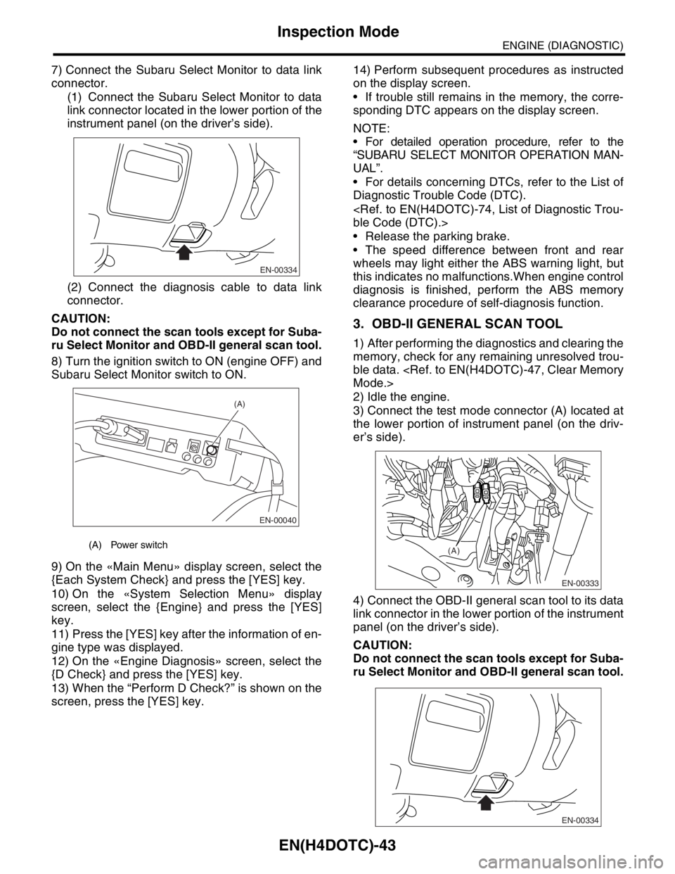
7) Connect the Subaru Select Monitor to data link
connector.
(1) Connect the Subaru Select Monitor to data
link connector located in the lower portion of the
instrument panel (on the driver’s side).
(2) Connect the diagnosis cable to data link
connector.
CAUTION:
Do not connect the scan tools except for Suba-
ru Select Monitor and OBD-II general scan tool.
8) Turn the ignition switch to ON (engine OFF) and
Subaru Select Monitor switch to ON.
9) On the «Main Menu» display screen, select the
{Each System Check} and press the [YES] key.
10) On the «System Selection Menu» display
screen, select the {Engine} and press the [YES]
key.
11) Press the [YES] key after the information of en-
gine type was displayed.
12) On the «Engine Diagnosis» screen, select the
{D Check} and press the [YES] key.
13) When the “Perform D Check?” is shown on the
screen, press the [YES] key.14) Perform subsequent procedures as instructed
on the display screen.
If trouble still remains in the memory, the corre-
sponding DTC appears on the display screen.
NOTE:
For detailed operation procedure, refer to the
“SUBARU SELECT MONITOR OPERATION MAN-
UAL”.
For details concerning DTCs, refer to the List of
Diagnostic Trouble Code (DTC).
Release the parking brake.
The speed difference between front and rear
wheels may light either the ABS warning light, but
this indicates no malfunctions.When engine control
diagnosis is finished, perform the ABS memory
clearance procedure of self-diagnosis function.
3. OBD-II GENERAL SCAN TOOL
1) After performing the diagnostics and clearing the
memory, check for any remaining unresolved trou-
ble data.
2) Idle the engine.
3) Connect the test mode connector (A) located at
the lower portion of instrument panel (on the driv-
er’s side).
4) Connect the OBD-II general scan tool to its data
link connector in the lower portion of the instrument
panel (on the driver’s side).
CAUTION:
Do not connect the scan tools except for Suba-
ru Select Monitor and OBD-II general scan tool.
(A) Power switch
EN-00334
EN-00040
(A)
EN-00333
(A)
EN-00334
Page 1677 of 2870

EN(H4DOTC)-47
ENGINE (DIAGNOSTIC)
Clear Memory Mode
14.Clear Memory Mode
A: OPERATION
1. SUBARU SELECT MONITOR (NORMAL
MODE)
1) On the «Main Menu» display screen, select the
{Each System Check} and press the [YES] key.
2) On the «System Selection Menu» display
screen, select the {Engine} and press the [YES]
key.
3) Press the [YES] key after the information of en-
gine type was displayed.
4) On the «Engine Diagnosis» display screen, se-
lect the {Memory Clear} and press the [YES] key.
5) When the “Done” are shown on the display
screen, turn the Subaru Select Monitor to OFF after
turning the ignition switch to OFF.
NOTE:
For detailed operation procedure, refer to the “SUBA-
RU SELECT MONITOR OPERATION MANUAL”.
2. SUBARU SELECT MONITOR (OBD
MODE)
1) On the «Main Menu» display screen, select the
{Each System Check} and press the [YES] key.
2) On the «System Selection Menu» display screen,
select the {Engine} and press the [YES] key.
3) Press the [YES] key after the information of en-
gine type was displayed.
4) On the «Engine Diagnosis» display screen, se-
lect the {OBD System} and press the [YES] key.
5) On the «OBD Menu» display screen, select the
{DTC Clear} and press the [YES] key.
6) When the “Perform Diagnostic Code(s) Clear?”
is shown on the screen, press the [YES] key.
7) Turn the ignition switch to OFF and then turn the
SUBARU SELECT MONITOR to OFF.
NOTE:
For detailed operation procedure, refer to the “SUBA-
RU SELECT MONITOR OPERATION MANUAL”.
3. OBD-II GENERAL SCAN TOOL
For clear memory procedures using the OBD-II
general scan tool, refer to the OBD-II General Scan
Tool Instruction Manual.
Page 1678 of 2870

EN(H4DOTC)-48
ENGINE (DIAGNOSTIC)
Compulsory Valve Operation Check Mode
15.Compulsory Valve Operation
Check Mode
A: OPERATION
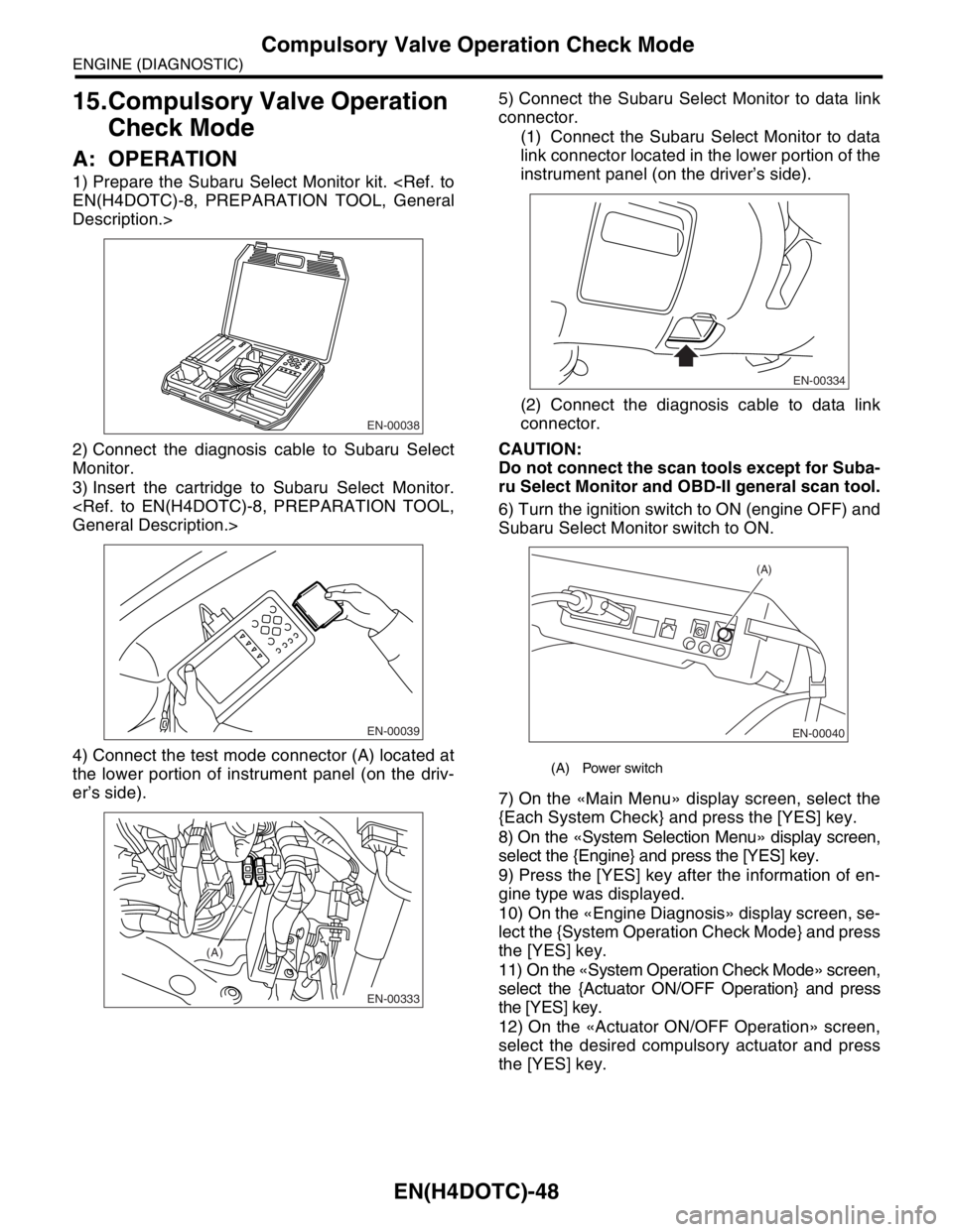
1) Prepare the Subaru Select Monitor kit.
Description.>
2) Connect the diagnosis cable to Subaru Select
Monitor.
3) Insert the cartridge to Subaru Select Monitor.
4) Connect the test mode connector (A) located at
the lower portion of instrument panel (on the driv-
er’s side).5) Connect the Subaru Select Monitor to data link
connector.
(1) Connect the Subaru Select Monitor to data
link connector located in the lower portion of the
instrument panel (on the driver’s side).
(2) Connect the diagnosis cable to data link
connector.
CAUTION:
Do not connect the scan tools except for Suba-
ru Select Monitor and OBD-II general scan tool.
6) Turn the ignition switch to ON (engine OFF) and
Subaru Select Monitor switch to ON.
7) On the «Main Menu» display screen, select the
{Each System Check} and press the [YES] key.
8) On the «System Selection Menu» display screen,
select the {Engine} and press the [YES] key.
9) Press the [YES] key after the information of en-
gine type was displayed.
10) On the «Engine Diagnosis» display screen, se-
lect the {System Operation Check Mode} and press
the [YES] key.
11) On the «System Operation Check Mode» screen,
select the {Actuator ON/OFF Operation} and press
the [YES] key.
12) On the «Actuator ON/OFF Operation» screen,
select the desired compulsory actuator and press
the [YES] key.
EN-00038
EN-00039
EN-00333
(A)
(A) Power switch
EN-00334
EN-00040
(A)
Page 1679 of 2870
![SUBARU FORESTER 2004 Service Repair Manual EN(H4DOTC)-49
ENGINE (DIAGNOSTIC)
Compulsory Valve Operation Check Mode
13) Pressing the [NO] key completes the compul-
sory operation check mode.The display will then re-
turn to the «Actuator ON/OF SUBARU FORESTER 2004 Service Repair Manual EN(H4DOTC)-49
ENGINE (DIAGNOSTIC)
Compulsory Valve Operation Check Mode
13) Pressing the [NO] key completes the compul-
sory operation check mode.The display will then re-
turn to the «Actuator ON/OF](/manual-img/17/57426/w960_57426-1678.png)
EN(H4DOTC)-49
ENGINE (DIAGNOSTIC)
Compulsory Valve Operation Check Mode
13) Pressing the [NO] key completes the compul-
sory operation check mode.The display will then re-
turn to the «Actuator ON/OFF Operation» screen.
A list of the support data is shown in the following
table.
NOTE:
The following parts will be displayed but not func-
tional.
For detailed operation procedure, refer to the
“SUBARU SELECT MONITOR OPERATION MAN-
UAL”.
Description Display
Compulsory fuel pump relay operation
checkFuel Pump
Compulsory radiator fan relay operation
checkRadiator Fan
Relay
Compulsory air conditioning relay oper-
ation checkA/C Compressor
Relay
Compulsory purge control solenoid
valve operation checkCPC Solenoid
Compulsory wastegate control sole-
noid valve operation checkWastegate con-
trol solenoid
Display
EGR Solenoid
ASV Solenoid
PCV Solenoid
Vent Control Solenoid
FICD Solenoid
Pressure Switching Solenoid1
Pressure Switching Solenoid2
EXH. Bypass Control Permit Flag
AAI Solenoid
Atmospheric pressure switching solenoid
Page 1684 of 2870

EN(H4DOTC)-54
ENGINE (DIAGNOSTIC)
Malfunction Indicator Light
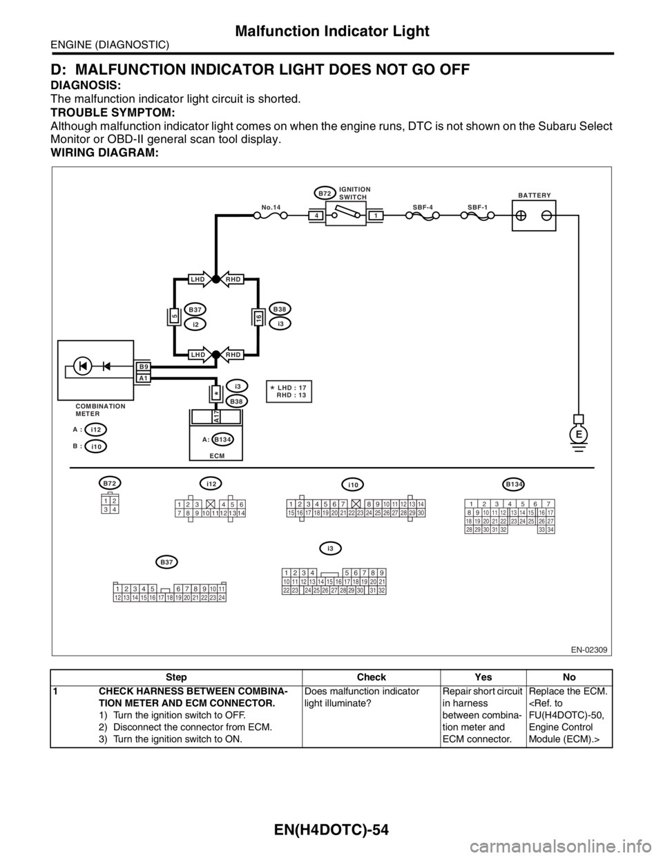
D: MALFUNCTION INDICATOR LIGHT DOES NOT GO OFF
DIAGNOSIS:
The malfunction indicator light circuit is shorted.
TROUBLE SYMPTOM:
Although malfunction indicator light comes on when the engine runs, DTC is not shown on the Subaru Select
Monitor or OBD-II general scan tool display.
WIRING DIAGRAM:
Step Check Yes No
1 CHECK HARNESS BETWEEN COMBINA-
TION METER AND ECM CONNECTOR.
1) Turn the ignition switch to OFF.
2) Disconnect the connector from ECM.
3) Turn the ignition switch to ON.Does malfunction indicator
light illuminate?Repair short circuit
in harness
between combina-
tion meter and
ECM connector.Replace the ECM.
Engine Control
Module (ECM).>
EN-02309
BATTERYIGNITION
SWITCH
SBF-4SBF-1
B72
B72
B38
B134
ECM
i3
E
14
RHD
RHD
A17
B37
i12 A :
i10 B :
i12i10B134
i3
i2
LHD
LHD
5
COMBINATION
METER
3412
123 456
789 121310 11 14
*
16
B38
i3
B37No.14
*LHD : 17
RHD : 13
B9
A1
34
12 8910 11
12 13 14 15 16 17 18 19 20 21 22 23 24567219
32
1234 5610 11 12 13 14 15716
23 3019 20
22 26 27 28 29817
24 3118
25
12345678910111213141516171819202122232425262728293056 7
82 1
94 310
24 22 23 25 11 12 13 14 15
26 27
2816 17
18 19 20 21
33 34 29
32 30 31
A:
Page 1691 of 2870

EN(H4DOTC)-61
ENGINE (DIAGNOSTIC)
Diagnostics for Engine Starting Failure
Step Check Yes No
1 CHECK OPERATION OF STARTER MOTOR.Does the starter motor oper-
ate?Go to step 2.Go to step 3.
2 CHECK DTC.Is DTC displayed?
TION, Read Diagnostic Trouble
Code (DTC).>Inspect the rele-
vant DTC using
List of Diagnostic
Trouble Code
(DTC).
List of Diagnostic
Trouble Code
(DTC).>Go to step 3.
3 CHECK INPUT SIGNAL FOR STARTER MO-
TOR.
1) Turn the ignition switch to OFF.
2) Disconnect the connector from starter
motor.
3) Turn the ignition switch to START.
4) Measure the power supply voltage between
starter motor connector terminal and engine
ground.
Connector & terminal
(B14) No. 1 (+) — Engine ground (
−):Is the voltage more than 10 V? Go to step 4.Go to step 5.
4 CHECK GROUND CIRCUIT OF STARTER
MOTOR.
1) Turn the ignition switch to OFF.
2) Measure the resistance of ground cable
between ground cable terminal and engine
ground.Is the resistance less than 5
Ω?Check the starter
motor.
Starter.>Repair open circuit
of ground cable.
5 CHECK HARNESS BETWEEN BATTERY
AND IGNITION SWITCH CONNECTOR.
1) Turn the ignition switch to OFF.
2) Disconnect the connector from ignition
switch.
3) Measure the power supply voltage between
ignition switch connector and chassis ground.
Connector & terminal
(B72) No. 1 (+) — Chassis ground (
−):Is the voltage more than 10 V? Go to step 6.Check the follow-
ing and repair if
necessary.
Brown out
fuse
Open circuit
in harness
between igni-
tion switch and
battery.
6 CHECK HARNESS BETWEEN BATTERY
AND IGNITION SWITCH CONNECTOR.
1) Connect the connector to ignition switch.
2) Turn the ignition switch to START.
3) Measure the voltage between ignition
switch and chassis ground.
Connector & terminal
(B72) No. 3 (+) — Chassis ground (
−):Is the voltage more than 10 V? Repair open circuit
between ignition
switch and starter
motor circuit.Go to step 7.
7 CHECK POOR CONTACT.
Check poor contact in ignition switch connec-
tor.Is there poor contact in ignition
switch connector?Repair poor con-
tact in ignition
switch connector.Replace the igni-
tion switch.