2004 SUBARU FORESTER center differential
[x] Cancel search: center differentialPage 666 of 2870

TRANSFER CASE
TC
Page
1. General Description ....................................................................................2
2. Transfer Case and Extension (5MT) ...........................................................3
3. Transfer Clutch and Extension (4AT) ..........................................................4
4. Oil Seal........................................................................................................5
5. Transfer Drive Gear (5MT) ..........................................................................6
6. Transfer Driven Gear (5MT) ........................................................................7
7. Reduction Drive Gear (4AT without VTD) ...................................................8
8. Reduction Driven Gear (4AT without VTD) .................................................9
9. Center Differential .....................................................................................10
10. Transfer Clutch Pressure Test ..................................................................11
11. Transfer Duty Solenoid and Valve Body ...................................................12
Page 675 of 2870

TC-10
TRANSFER CASE
Center Differential
9. Center Differential
A: NOTE
For removal, installation and inspection work, refer
to “5MT” section.
Page 715 of 2870

ID-6
IDENTIFICATION
Identification
Transmission
TY755XF3AA
Rear differential 1
VA1REK
Rear differential 2
HP
Option code
ECAJ
Digits Code Meaning Details
1 T Transmission T: Transmission
2 Y Transmission type Y: Full-time AWD MT center differential
Z: Full-time AWD AT MPT
3 and 4 75 Classification 75: MT
1A: AT
1B: AT
55 Series 3: AT
5: MT
6 X Transmission specifica-
tionsV: Full-time AWD 5-speed MT with viscous coupling center dif-
ferential single range
X: Full-time AWD 5-speed MT Dual range with viscous cou-
pling center differential
Z: Full-time AWD 4-speed AT with MPT
L: Full-time AWD 4-speed AT with MPT Turbo
7 F Mounted body F: 2.5L SOHC
R: 2.0L SOHC
N: 2.0L DOHC Turbo
H: 2.5L DOHC Turbo
8 3 Minor change 3: Initial
9 to 10 AA Detailed specifications Used when ordering parts. See the parts catalog for details.
Digits Code Meaning Details
1 V Fo r AW D V: AW D
2 A Type A: A type
3 1 Hypoid gear diameter
mm (in)1: 152 (6.0) dia.
4 R Installation position R: Rear
5 E Reduction gear ratio E: 4.111
F: 4.444
6 K Specification differ-
ences—
Code Reduction gear ratio LSD
HP 4.111 Viscous
JP 4.111 Viscous
CF 4.444 Viscous
Digits Code Meaning Details
1 to 2 EC Destination EC: EC
K4: K4
KS: KS
EK: EK
KA: KA
3 to 4 AJ Main option of vehicle —
Page 763 of 2870
PM-26
PERIODIC MAINTENANCE SERVICE
ATF
16.ATF
A: INSPECTION
CAUTION:
The level of ATF varies with fluid temperature.
Pay attention to the fluid temperature when
checking ATF level.
1) Raise the ATF temperature by driving a distance
of 5 to 10 km (3 to 6 miles). Otherwise, idle the en-
gine to raise ATF temperature to 70 — 80°C (158
— 176°F) on Subaru Select Monitor.
TION, Subaru Select Monitor.>
2) Make sure the vehicle is level.
3) After selecting all positions (P, R, N, D, 3, 2, 1),
set the select lever in “P” range. Measure the ATF
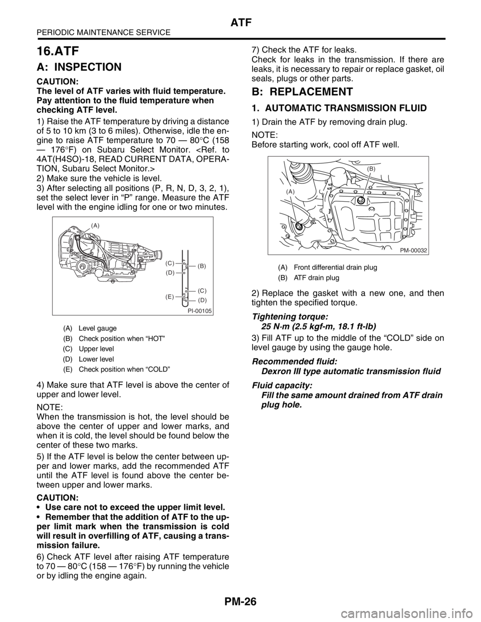
level with the engine idling for one or two minutes.
4) Make sure that ATF level is above the center of
upper and lower level.
NOTE:
When the transmission is hot, the level should be
above the center of upper and lower marks, and
when it is cold, the level should be found below the
center of these two marks.
5) If the ATF level is below the center between up-
per and lower marks, add the recommended ATF
until the ATF level is found above the center be-
tween upper and lower marks.
CAUTION:
Use care not to exceed the upper limit level.
Remember that the addition of ATF to the up-
per limit mark when the transmission is cold
will result in overfilling of ATF, causing a trans-
mission failure.
6) Check ATF level after raising ATF temperature
to 70 — 80°C (158 — 176°F) by running the vehicle
or by idling the engine again.7) Check the ATF for leaks.
Check for leaks in the transmission. If there are
leaks, it is necessary to repair or replace gasket, oil
seals, plugs or other parts.
B: REPLACEMENT
1. AUTOMATIC TRANSMISSION FLUID
1) Drain the ATF by removing drain plug.
NOTE:
Before starting work, cool off ATF well.
2) Replace the gasket with a new one, and then
tighten the specified torque.
Tightening torque:
25 N·m (2.5 kgf-m, 18.1 ft-lb)
3) Fill ATF up to the middle of the “COLD” side on
level gauge by using the gauge hole.
Recommended fluid:
Dexron III type automatic transmission fluid
Fluid capacity:
Fill the same amount drained from ATF drain
plug hole.
(A) Level gauge
(B) Check position when “HOT”
(C) Upper level
(D) Lower level
(E) Check position when “COLD”
PI-00105
COLD
LFHOT LF
(A)
(C)
(D)
(C)
(D)
(E)
(B)(A) Front differential drain plug
(B) ATF drain plug
PM-00032
(B)
(A)
Page 2342 of 2870
4AT-30
AUTOMATIC TRANSMISSION
Automatic Transmission Fluid
2. Automatic Transmission Flu-
id
A: INSPECTION
NOTE:
The level of ATF varies with fluid temperature. Pay
attention to the ATF temperature when checking
ATF level.
1) Raise the ATF temperature by driving a distance
of 5 to 10 km (3 to 6 miles). Otherwise, idle the en-
gine to raise ATF temperature to 70 — 80°C (158
— 176°F) on Subaru Select Monitor.
TION, Subaru Select Monitor.>
2) Make sure the vehicle is level.
3) After selecting all positions (P, R, N, D, 3, 2, 1),
set the select lever in “P” range. Measure the ATF
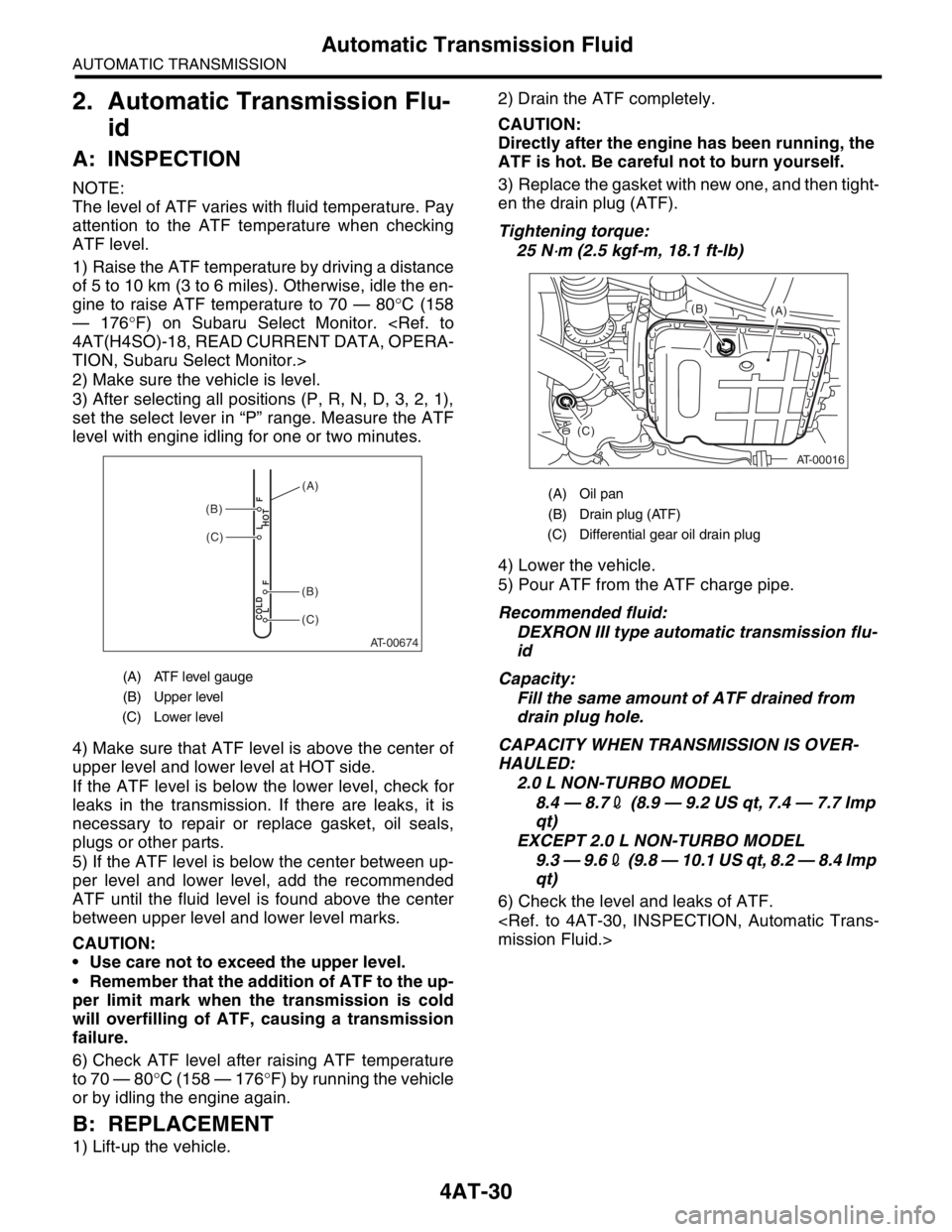
level with engine idling for one or two minutes.
4) Make sure that ATF level is above the center of
upper level and lower level at HOT side.
If the ATF level is below the lower level, check for
leaks in the transmission. If there are leaks, it is
necessary to repair or replace gasket, oil seals,
plugs or other parts.
5) If the ATF level is below the center between up-
per level and lower level, add the recommended
ATF until the fluid level is found above the center
between upper level and lower level marks.
CAUTION:
Use care not to exceed the upper level.
Remember that the addition of ATF to the up-
per limit mark when the transmission is cold
will overfilling of ATF, causing a transmission
failure.
6) Check ATF level after raising ATF temperature
to 70 — 80°C (158 — 176°F) by running the vehicle
or by idling the engine again.
B: REPLACEMENT
1) Lift-up the vehicle.2) Drain the ATF completely.
CAUTION:
Directly after the engine has been running, the
ATF is hot. Be careful not to burn yourself.
3) Replace the gasket with new one, and then tight-
en the drain plug (ATF).
Tightening torque:
25 N
⋅m (2.5 kgf-m, 18.1 ft-lb)
4) Lower the vehicle.
5) Pour ATF from the ATF charge pipe.
Recommended fluid:
DEXRON III type automatic transmission flu-
id
Capacity:
Fill the same amount of ATF drained from
drain plug hole.
CAPACITY WHEN TRANSMISSION IS OVER-
HAULED:
2.0 L NON-TURBO MODEL
8.4 — 8.72 (8.9 — 9.2 US qt, 7.4 — 7.7 Imp
qt)
EXCEPT 2.0 L NON-TURBO MODEL
9.3 — 9.62 (9.8 — 10.1 US qt, 8.2 — 8.4 Imp
qt)
6) Check the level and leaks of ATF.
(A) ATF level gauge
(B) Upper level
(C) Lower level
AT-00674
COLD
LFHOT LF
(C)
(C)
(B)
(B)
(A)(A) Oil pan
(B) Drain plug (ATF)
(C) Differential gear oil drain plug
AT-00016
(A) (B)
(C)
Page 2363 of 2870
4AT-50
AUTOMATIC TRANSMISSION
Differential Side Retainer Oil Seal
12.Differential Side Retainer Oil
Seal
A: INSPECTION
Check the leakage of gear oil from differential side
retainer oil seal part.
If there is oil leakage, replace the oil seal.
B: REPLACEMENT
1) Lift-up the vehicle.
2) Remove the front exhaust pipe and center ex-
haust pipe.
(Non-turbo model)
(Turbo model)
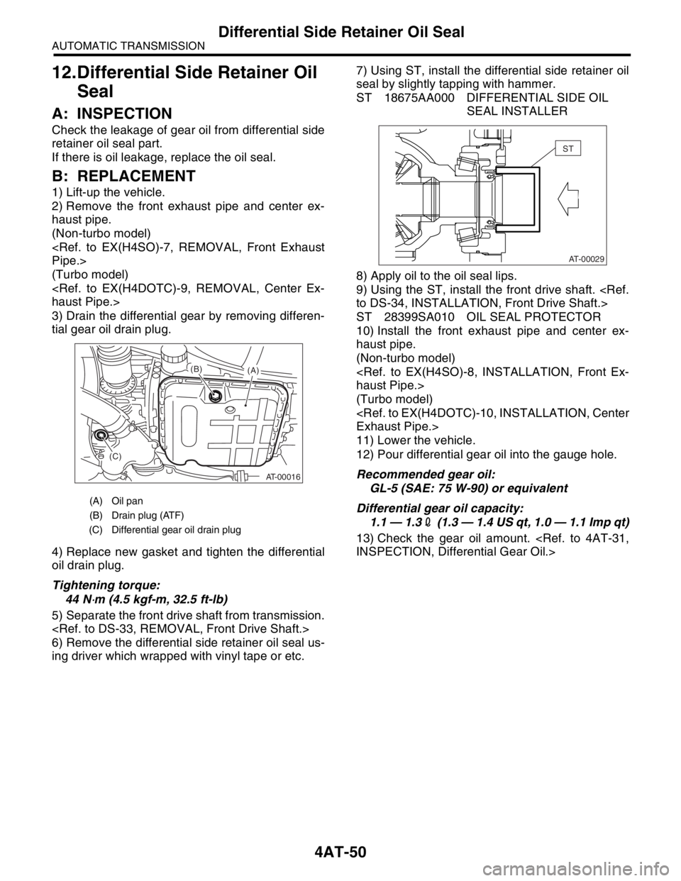
3) Drain the differential gear by removing differen-
tial gear oil drain plug.
4) Replace new gasket and tighten the differential
oil drain plug.
Tightening torque:
44 N
⋅m (4.5 kgf-m, 32.5 ft-lb)
5) Separate the front drive shaft from transmission.
6) Remove the differential side retainer oil seal us-
ing driver which wrapped with vinyl tape or etc.7) Using ST, install the differential side retainer oil
seal by slightly tapping with hammer.
ST 18675AA000 DIFFERENTIAL SIDE OIL
SEAL INSTALLER
8) Apply oil to the oil seal lips.
9) Using the ST, install the front drive shaft.
ST 28399SA010 OIL SEAL PROTECTOR
10) Install the front exhaust pipe and center ex-
haust pipe.
(Non-turbo model)
(Turbo model)
11) Lower the vehicle.
12) Pour differential gear oil into the gauge hole.
Recommended gear oil:
GL-5 (SAE: 75 W-90) or equivalent
Differential gear oil capacity:
1.1 — 1.32 (1.3 — 1.4 US qt, 1.0 — 1.1 Imp qt)
13) Check the gear oil amount.
(A) Oil pan
(B) Drain plug (ATF)
(C) Differential gear oil drain plug
AT-00016
(A) (B)
(C)
AT-00029
ST
Page 2368 of 2870
4AT-55
AUTOMATIC TRANSMISSION
Front Vehicle Speed Sensor
14.Front Vehicle Speed Sensor
A: REMOVAL
1) Set the vehicle on a lift.
2) Disconnect the ground cable from battery.
3) Remove the air cleaner case. (Non-turbo mod-
el).
4) Remove the intercooler. (Turbo model)
5) Disconnect the transmission connector.
6) Remove the pitching stopper.
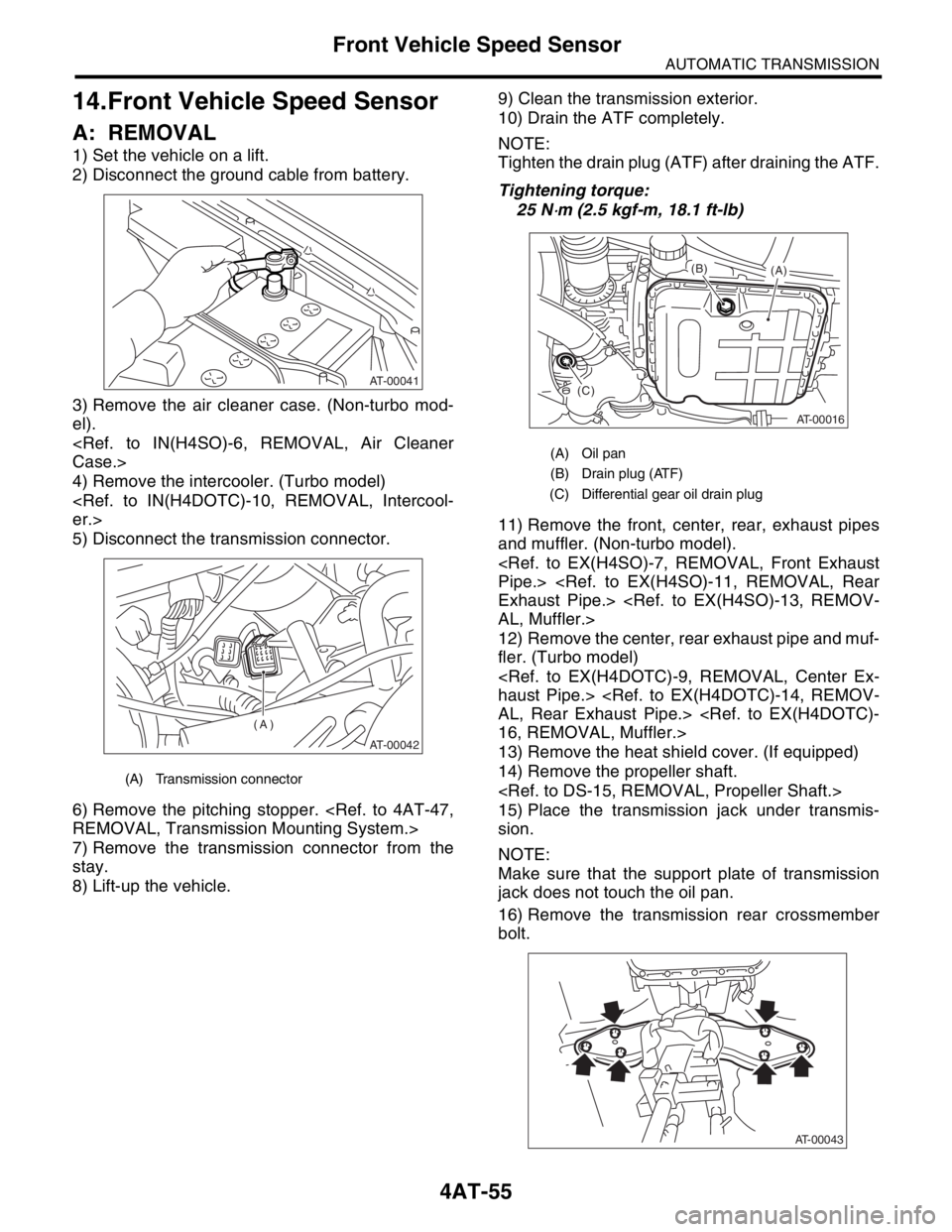
7) Remove the transmission connector from the
stay.
8) Lift-up the vehicle.9) Clean the transmission exterior.
10) Drain the ATF completely.
NOTE:
Tighten the drain plug (ATF) after draining the ATF.
Tightening torque:
25 N
⋅m (2.5 kgf-m, 18.1 ft-lb)
11) Remove the front, center, rear, exhaust pipes
and muffler. (Non-turbo model).
12) Remove the center, rear exhaust pipe and muf-
fler. (Turbo model)
13) Remove the heat shield cover. (If equipped)
14) Remove the propeller shaft.
15) Place the transmission jack under transmis-
sion.
NOTE:
Make sure that the support plate of transmission
jack does not touch the oil pan.
16) Remove the transmission rear crossmember
bolt.
(A) Transmission connector
AT-00041
AT-00042
(A)
(A) Oil pan
(B) Drain plug (ATF)
(C) Differential gear oil drain plug
AT-00016
(A) (B)
(C)
AT-00043
Page 2386 of 2870
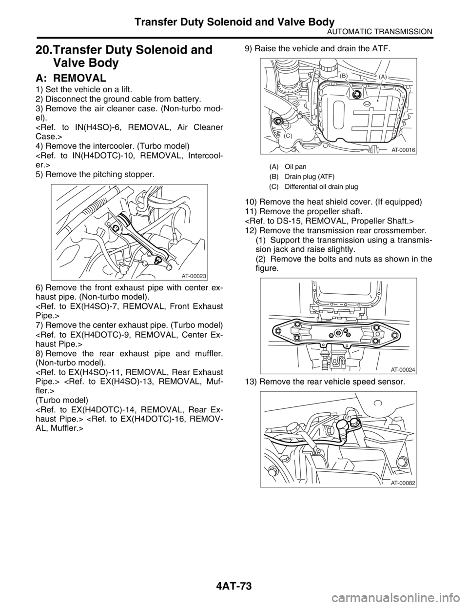
4AT-73
AUTOMATIC TRANSMISSION
Transfer Duty Solenoid and Valve Body
20.Transfer Duty Solenoid and
Valve Body
A: REMOVAL
1) Set the vehicle on a lift.
2) Disconnect the ground cable from battery.
3) Remove the air cleaner case. (Non-turbo mod-
el).
4) Remove the intercooler. (Turbo model)
5) Remove the pitching stopper.
6) Remove the front exhaust pipe with center ex-
haust pipe. (Non-turbo model).
7) Remove the center exhaust pipe. (Turbo model)
8) Remove the rear exhaust pipe and muffler.
(Non-turbo model).
(Turbo model)
10) Remove the heat shield cover. (If equipped)
11) Remove the propeller shaft.
12) Remove the transmission rear crossmember.
(1) Support the transmission using a transmis-
sion jack and raise slightly.
(2) Remove the bolts and nuts as shown in the
figure.
13) Remove the rear vehicle speed sensor.
AT-00023
(A) Oil pan
(B) Drain plug (ATF)
(C) Differential oil drain plug
AT-00016
(A) (B)
(C)
AT-00024
AT-00082