5MT-58
MANUAL TRANSMISSION AND DIFFERENTIAL
Center Differential
14.Center Differential
A: REMOVAL
1) Remove the manual transmission assembly
from vehicle.
Transmission Assembly.>
2) Remove the transfer case with extension case
assembly.
Case and Extension Case Assembly.>
3) Remove the extension case assembly.
5MT-50, REMOVAL, Transfer Case and Extension
Case Assembly.>
4) Remove the transfer driven gear.
56, REMOVAL, Transfer Driven Gear.>
5) Remove the center differential.
B: INSTALLATION
1) Install the center differential into transfer case.
2) Install the transfer driven gear.
INSTALLATION, Transfer Driven Gear.>
3) Install the extension case assembly.
5MT-50, INSTALLATION, Transfer Case and Ex-
tension Case Assembly.>
4) Install the transfer case with extension case as-
sembly.
fer Case and Extension Case Assembly.>
5) Install the back-up light switch and neutral posi-
tion switch.
Switches and Harness.>
6) Install the manual transmission assembly to ve-
hicle.
Transmission Assembly.>
C: DISASSEMBLY
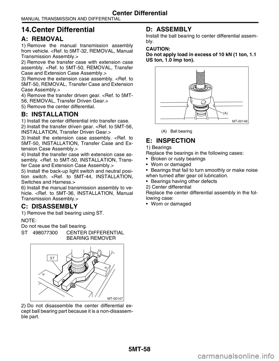
1) Remove the ball bearing using ST.
NOTE:
Do not reuse the ball bearing.
ST 498077300 CENTER DIFFERENTIAL
BEARING REMOVER
2) Do not disassemble the center differential ex-
cept ball bearing part because it is a non-disassem-
ble part.
D: ASSEMBLY
Install the ball bearing to center differential assem-
bly.
CAUTION:
Do not apply load in excess of 10 kN (1 ton, 1.1
US ton, 1.0 Imp ton).
E: INSPECTION
1) Bearings
Replace the bearings in the following cases:
Broken or rusty bearings
Worn or damaged
Bearings that fail to turn smoothly or make noise
when turned after gear oil lubrication.
Bearings having other defects
2) Center differential
Replace the center differential assembly in the fol-
lowing case:
Worn or damaged
MT-00147
ST
(A) Ball bearing
MT-00148 (A)
5MT-88
MANUAL TRANSMISSION AND DIFFERENTIAL
Drive Pinion Shaft Assembly
8) Select one to three shims from the next table for
the value determined as described above and take
a shim thickness which is closest to the indicated
value.
9) Install the differential assembly.
96, INSTALLATION, Front Differential Assembly.>
10) Set the transmission main shaft assembly and
drive pinion assembly in position. (So there is no
clearance between the two when moved all the way
to the front). Inspect the suitable 1st-2nd, 3rd-4th
and 5th shifter fork so that coupling sleeve and re-
verse driven gear are positioned in the center of
their synchronizing mechanisms.
INSPECTION, Drive Pinion Shaft Assembly.>
11) Install the transmission case.
INSTALLATION, Transmission Case.>
12) Install the transfer case with extension case as-
sembly.
fer Case and Extension Case Assembly.>
13) Install the manual transmission assembly to ve-
hicle.
sembly.>C: DISASSEMBLY
NOTE:
Attach a cloth to the end of driven shaft (on the fric-
tional side of thrust needle bearing) during disas-
sembly or reassembly to prevent damage.
1) Straighten the lock nut at staked portion. Re-
move the lock nut using ST1, ST2 and ST3.
ST1 899884100 HOLDER
ST2 498427100 STOPPER
ST3 899988608 SOCKET WRENCH (27)
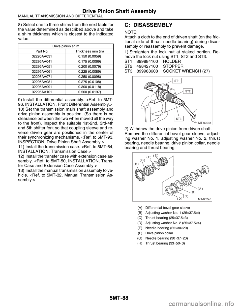
2) Withdraw the drive pinion from driven shaft.
Remove the differential bevel gear sleeve, adjust-
ing washer No. 1, adjusting washer No. 2, thrust
bearing, needle bearing, drive pinion collar, needle
bearing and thrust bearing.
Drive pinion shim
Part No. Thickness mm (in)
32295AA031 0.150 (0.0059)
32295AA041 0.175 (0.0069)
32295AA051 0.200 (0.0079)
32295AA061 0.225 (0.0089)
32295AA071 0.250 (0.0098)
32295AA081 0.275 (0.0108)
32295AA091 0.300 (0.0118)
32295AA101 0.500 (0.0197)
(A) Differential bevel gear sleeve
(B) Adjusting washer No. 1 (25×37.5×t)
(C) Thrust bearing (25×37.5×3)
(D) Adjusting washer No. 2 (25×37.5×4)
(E) Needle bearing (25×30×20)
(F) Drive pinion collar
(G) Needle bearing (30×37×23)
(H) Thrust bearing (33×50×3)
ST1
ST2
MT-00244
ST3
MT-00245
(B)
(D)(C)(A) (F)
(H)(G)(E)