Page 117 of 2870
AB-17
AIRBAG SYSTEM
Side Airbag Module
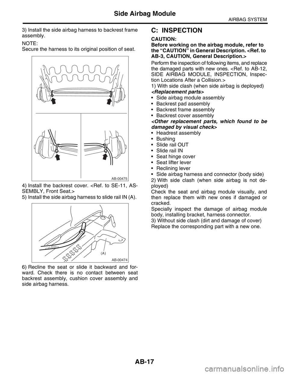
3) Install the side airbag harness to backrest frame
assembly.
NOTE:
Secure the harness to its original position of seat.
4) Install the backrest cover.
SEMBLY, Front Seat.>
5) Install the side airbag harness to slide rail IN (A).
6) Recline the seat or slide it backward and for-
ward. Check there is no contact between seat
backrest assembly, cushion cover assembly and
side airbag harness. C: INSPECTION
CAUTION:
Before working on the airbag module, refer to
the “CAUTION” in General Description.
AB-3, CAUTION, General Description.>
Perform the inspection of following items, and replace
the damaged parts with new ones.
SIDE AIRBAG MODULE, INSPECTION, Inspec-
tion Locations After a Collision.>
1) With side clash (when side airbag is deployed)
Side airbag module assembly
Backrest pad assembly
Backrest frame assembly
Backrest cover assembly
damaged by visual check>
Headrest assembly
Bushing
Slide rail OUT
Slide rail IN
Seat hinge cover
Seat lifter lever
Reclining lever
Side airbag harness and connector (body side)
2) With side clash (when side airbag is not de-
ployed)
Check the seat and airbag module visually, and
then replace them with new ones if damaged or
cracked.
Specially inspect the damage of airbag module
body, installing bracket, harness connector.
3) Without side clash (dirt and damage of cover)
Replace the corresponding part with a new one.
AB-00475
AB-00474
(A)
Page 407 of 2870
SE-3
SEAT
General Description
(1) Backrest cover (14) Connecting wire (27) Headrest lock bushing
(2) Backrest pad (15) Outer slide rail (28) Backrest frame ASSY
(3) Backrest side cover (16)
TORX
® bolt
(4) Armrest ASSY (17) Bolt cover RHTightening torque: N·m (kgf-m, ft-lb)
(5) Hinge cover cap (18) Reclining leverT1: 5.9 (0.6, 4.4)
(6) Seat hinge outer cover LH (19) Seat hinge outer cover RHT2: 10 (1.0, 7.4)
(7) Seat hinge inner cover LH (20) Seat lifter dialT3: 17.7 (1.8, 13.0)
(8) Bolt cover LH (21) Seat hinge inner cover RHT4: 20 (2.0, 14.8)
(9) Seat cushion cover (22) Seat heater unitT5: 30 (3.0, 22.1)
(10) Seat cushion pad ASSY (23) Side airbag module ASSYT6: 52 (5.3, 38.3)
(11) Seat cushion frame ASSY (24) Support pad (A)T7: 53 (5.4, 39.0)
(12) Inner belt (25) Support pad (B)
(13) Inner slide rail (26) Headrest ASSY
Page 967 of 2870

ME(H4SO)-96
MECHANICAL
Engine Noise
23.Engine Noise
A: INSPECTION
NOTE*:
When disconnecting fuel injector connector, the malfunction indicator light illuminates and DTC is stored in ECM memory.
Therefore, carry out the clear memory mode and inspection mode
after connecting fuel injector connector.Type of sound Condition Possible cause
Regular clicking soundSound increases as engine
speed increases. Valve mechanism is defective.
Incorrect valve clearance
Worn valve rocker
Worn camshaft
Broken valve spring
Heavy and dull clankOil pressure is low. Worn crankshaft main bearing
Worn connecting rod bearing (big end)
Oil pressure is normal. Loose flywheel mounting bolts
Damaged engine mounting
High-pitched clank (Spark
knock)Sound is noticeable when
accelerating with an overload. Ignition timing advanced
Accumulation of carbon inside combustion chamber
Wrong spark plug
Improper gasoline
Clank when engine speed is
medium (1,000 to 2,000 rpm).Sound is reduced when fuel
injector connector of noisy cyl-
inder is disconnected.
(NOTE*) Worn crankshaft main bearing
Worn bearing at crankshaft end of connecting rod
Knocking sound when engine
is operating under idling speed
and engine is warmSound is reduced when fuel
injector connector of noisy cyl-
inder is disconnected.
(NOTE*) Worn cylinder liner and piston ring
Broken or stuck piston ring
Worn piston pin and hole at piston end of connecting rod
Sound is not reduced if each
fuel injector connector is dis-
connected in turn. (NOTE*) Unusually worn valve lifter
Worn cam gear
Worn camshaft journal bore in crankcase
Squeaky sound — Insufficient generator lubrication
Rubbing sound — Defective generator brush and rotor contact
Gear scream when starting
engine— Defective ignition starter switch
Worn gear and starter pinion
Sound like polishing glass with
a dry cloth— Loose drive belt
Defective water pump shaft
Hissing sound — Loss of compression
Air leakage in air intake system, hoses, connections or mani-
folds
Timing belt noise — Loose timing belt
Belt contacting case/adjacent part
Valve tappet noise — Incorrect valve clearance
Page 1471 of 2870
ME(H4DOTC)-15
MECHANICAL
General Description
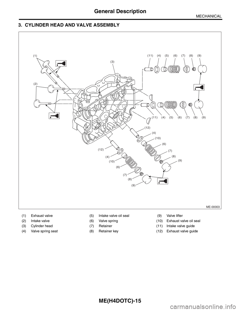
3. CYLINDER HEAD AND VALVE ASSEMBLY
(1) Exhaust valve (5) Intake valve oil seal (9) Valve lifter
(2) Intake valve (6) Valve spring (10) Exhaust valve oil seal
(3) Cylinder head (7) Retainer (11) Intake valve guide
(4) Valve spring seat (8) Retainer key (12) Exhaust valve guide
ME-00003
(3) (1)
(2)(11) (4) (5) (6) (7) (8) (9)
(11)
(12)
(12)(10)(4)
(4)(5) (6)
(6)(7)
(7)(8)
(8)(9)
(9)
(10) (4)
(6)
(7)
(8)
(9)
Page 1495 of 2870
ME(H4DOTC)-39
MECHANICAL
Valve Clearance
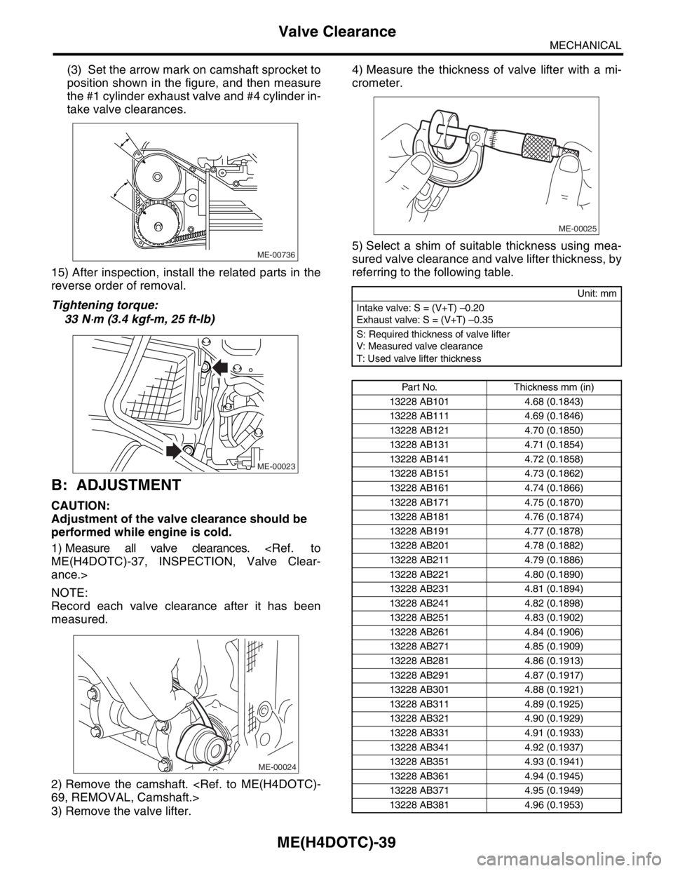
(3) Set the arrow mark on camshaft sprocket to
position shown in the figure, and then measure
the #1 cylinder exhaust valve and #4 cylinder in-
take valve clearances.
15) After inspection, install the related parts in the
reverse order of removal.
Tightening torque:
33 N
⋅m (3.4 kgf-m, 25 ft-lb)
B: ADJUSTMENT
CAUTION:
Adjustment of the valve clearance should be
performed while engine is cold.
1) Measure all valve clearances.
ME(H4DOTC)-37, INSPECTION, Valve Clear-
ance.>
NOTE:
Record each valve clearance after it has been
measured.
2) Remove the camshaft.
69, REMOVAL, Camshaft.>
3) Remove the valve lifter.4) Measure the thickness of valve lifter with a mi-
crometer.
5) Select a shim of suitable thickness using mea-
sured valve clearance and valve lifter thickness, by
referring to the following table.
ME-00736
ME-00023
ME-00024
Unit: mm
Intake valve: S = (V+T) –0.20
Exhaust valve: S = (V+T) –0.35
S: Required thickness of valve lifter
V: Measured valve clearance
T: Used valve lifter thickness
Part No. Thickness mm (in)
13228 AB101 4.68 (0.1843)
13228 AB111 4.69 (0.1846)
13228 AB121 4.70 (0.1850)
13228 AB131 4.71 (0.1854)
13228 AB141 4.72 (0.1858)
13228 AB151 4.73 (0.1862)
13228 AB161 4.74 (0.1866)
13228 AB171 4.75 (0.1870)
13228 AB181 4.76 (0.1874)
13228 AB191 4.77 (0.1878)
13228 AB201 4.78 (0.1882)
13228 AB211 4.79 (0.1886)
13228 AB221 4.80 (0.1890)
13228 AB231 4.81 (0.1894)
13228 AB241 4.82 (0.1898)
13228 AB251 4.83 (0.1902)
13228 AB261 4.84 (0.1906)
13228 AB271 4.85 (0.1909)
13228 AB281 4.86 (0.1913)
13228 AB291 4.87 (0.1917)
13228 AB301 4.88 (0.1921)
13228 AB311 4.89 (0.1925)
13228 AB321 4.90 (0.1929)
13228 AB331 4.91 (0.1933)
13228 AB341 4.92 (0.1937)
13228 AB351 4.93 (0.1941)
13228 AB361 4.94 (0.1945)
13228 AB371 4.95 (0.1949)
13228 AB381 4.96 (0.1953)
ME-00025
Page 1534 of 2870
ME(H4DOTC)-76
MECHANICAL
Cylinder Head Assembly
7) Install the timing belt assembly.
ME(H4DOTC)-60, INSTALLATION, Timing Belt
Assembly.>
8) Install the timing belt cover.
ME(H4DOTC)-57, INSTALLATION, Timing Belt
Cover.>
9) Install the crank pulley.
55, INSTALLATION, Crank Pulley.>
10) Install the V-belt.
INSTALLATION, V-belt.>
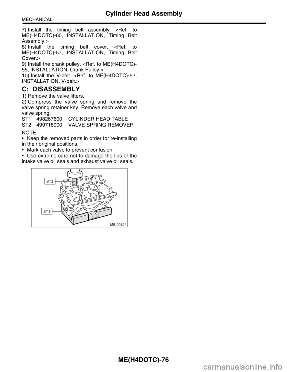
C: DISASSEMBLY
1) Remove the valve lifters.
2) Compress the valve spring and remove the
valve spring retainer key. Remove each valve and
valve spring.
ST1 498267600 CYLINDER HEAD TABLE
ST2 499718000 VALVE SPRING REMOVER
NOTE:
Keep the removed parts in order for re-installing
in their original positions.
Mark each valve to prevent confusion.
Use extreme care not to damage the lips of the
intake valve oil seals and exhaust valve oil seals.
ME-00124
ST1
ST2
Page 1535 of 2870
ME(H4DOTC)-77
MECHANICAL
Cylinder Head Assembly
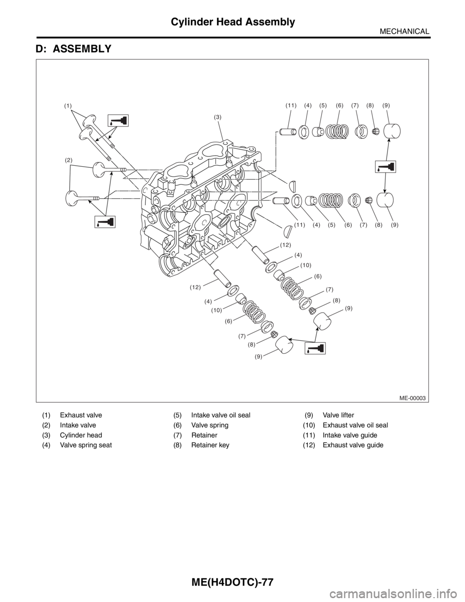
D: ASSEMBLY
(1) Exhaust valve (5) Intake valve oil seal (9) Valve lifter
(2) Intake valve (6) Valve spring (10) Exhaust valve oil seal
(3) Cylinder head (7) Retainer (11) Intake valve guide
(4) Valve spring seat (8) Retainer key (12) Exhaust valve guide
ME-00003
(3) (1)
(2)(11) (4) (5) (6) (7) (8) (9)
(11)
(12)
(12)(10)(4)
(4)(5) (6)
(6)(7)
(7)(8)
(8)(9)
(9)
(10) (4)
(6)
(7)
(8)
(9)
Page 1536 of 2870
ME(H4DOTC)-78
MECHANICAL
Cylinder Head Assembly
1) Installation of valve spring and valve.
(1) Coat the stem of each valve with engine oil
and insert the valve into valve guide.
NOTE:
When inserting the valve into valve guide, use spe-
cial care not to damage the oil seal lip.
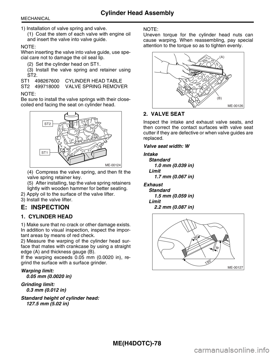
(2) Set the cylinder head on ST1.
(3) Install the valve spring and retainer using
ST2.
ST1 498267600 CYLINDER HEAD TABLE
ST2 499718000 VALVE SPRING REMOVER
NOTE:
Be sure to install the valve springs with their close-
coiled end facing the seat on cylinder head.
(4) Compress the valve spring, and then fit the
valve spring retainer key.
(5) After installing, tap the valve spring retainers
lightly with wooden hammer for better seating.
2) Apply oil to the surface of the valve lifter.
3) Install the valve lifter.
E: INSPECTION
1. CYLINDER HEAD
1) Make sure that no crack or other damage exists.
In addition to visual inspection, inspect the impor-
tant areas by means of red check.
2) Measure the warping of the cylinder head sur-
face that mates with crankcase by using a straight
edge (A) and thickness gauge (B).
If the warping exceeds 0.05 mm (0.0020 in), re-
grind the surface with a surface grinder.
Warping limit:
0.05 mm (0.0020 in)
Grinding limit:
0.3 mm (0.012 in)
Standard height of cylinder head:
127.5 mm (5.02 in)NOTE:
Uneven torque for the cylinder head nuts can
cause warping. When reassembling, pay special
attention to the torque so as to tighten evenly.
2. VALVE SEAT
Inspect the intake and exhaust valve seats, and
then correct the contact surfaces with valve seat
cutter if they are defective or when valve guides are
replaced.
Valve seat width: W
Intake
Standard
1.0 mm (0.039 in)
Limit
1.7 mm (0.067 in)
Exhaust
Standard
1.5 mm (0.059 in)
Limit
2.2 mm (0.087 in)
ME-00124
ST1
ST2
ME-00126
(A)
(B)
ME-00127
W