Page 593 of 1833
Special Service Tools
Tool number
Tool nameDescription
KV11229352
Measuring device
q
1KV11229350
Holder
q
2KV11229360
Nut
q
3KV11229370
Pin
q
4KV11254410
Dial gauge
NT570
Measuring set length of plunger spring
ST16540000
Pulley holder
NT628
Removing injection pump drive gear
a: 68 mm (2.68 in)
b: 8 mm (0.31 in)
KV11289004
Nozzle cleaning kit
q
1KV11290012
Box
q
2KV11290110
Brush
q
3KV11290122
Nozzle oil sump scraper
q
4KV11290140
Nozzle needle tip
cleaner
q
5KV11290150
Nozzle seat scraper
q
6KV11290210
Nozzle holder
q
7KV11290220
Nozzle hole cleaning
needle
NT296
KV11290632
Nozzle oil sump scraper
NT294
KV11292010
Nozzle centering device
NT293
PRECAUTIONS AND PREPARATIONTD27Ti
EC-318
http://vnx.su/
Page 594 of 1833
Tool number
Tool nameDescription
KV11100300
Nozzle holder socket
No. 2-4 injection nozzle
holder socket
NT563
KV111-05700
No. 1 injection nozzle
holder socket
NT648
PRECAUTIONS AND PREPARATIONTD27Ti
Special Service Tools (Cont'd)
EC-319
http://vnx.su/
Page 611 of 1833

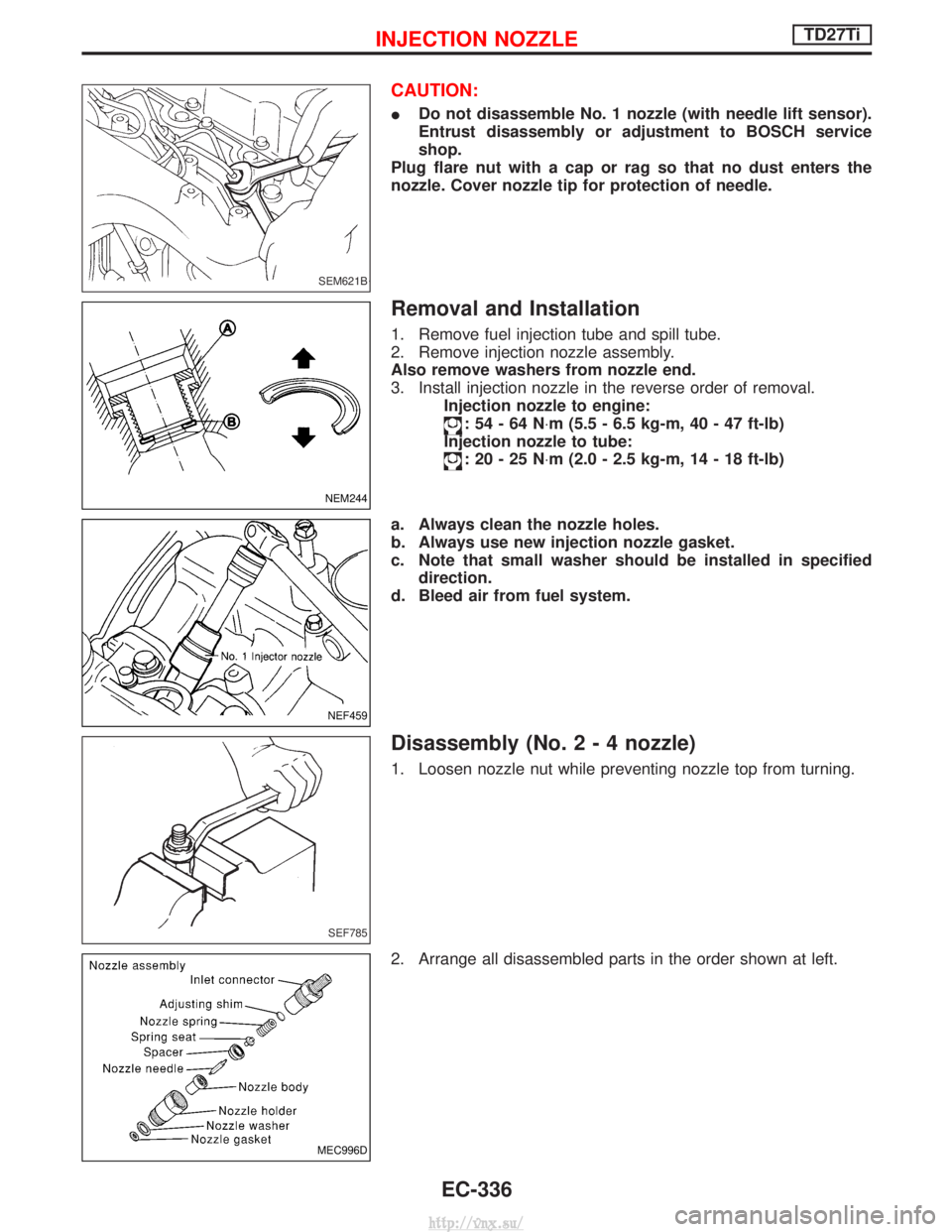
CAUTION:
IDo not disassemble No. 1 nozzle (with needle lift sensor).
Entrust disassembly or adjustment to BOSCH service
shop.
Plug flare nut with a cap or rag so that no dust enters the
nozzle. Cover nozzle tip for protection of needle.
Removal and Installation
1. Remove fuel injection tube and spill tube.
2. Remove injection nozzle assembly.
Also remove washers from nozzle end.
3. Install injection nozzle in the reverse order of removal. Injection nozzle to engine:
:54-64N ×m (5.5 - 6.5 kg-m, 40 - 47 ft-lb)
Injection nozzle to tube:
:20-25N ×m (2.0 - 2.5 kg-m, 14 - 18 ft-lb)
a. Always clean the nozzle holes.
b. Always use new injection nozzle gasket.
c. Note that small washer should be installed in specified direction.
d. Bleed air from fuel system.
Disassembly (No.2-4nozzle)
1. Loosen nozzle nut while preventing nozzle top from turning.
2. Arrange all disassembled parts in the order shown at left.
SEM621B
NEM244
NEF459
SEF785
MEC996D
INJECTION NOZZLETD27Ti
EC-336
http://vnx.su/
Page 625 of 1833
CONSULT-II
CONSULT-II INSPECTION PROCEDURE
1. Turn off ignition switch.
2. Connect ªCONSULT-IIº to data link connector for CONSULT-II.(Data link connector for CONSULT-II is located behind the fuse
box cover.)
3. Turn on ignition switch.
4. Touch ªSTARTº.
5. Touch ªENGINEº.
6. Perform each diagnostic test mode according to each service procedure.
For further information, see the CONSULT-II Operation Manual.
NRS122
YEC696A
YEC697A
ON BOARD DIAGNOSTIC SYSTEM DESCRIPTIONTD27Ti
EC-350
http://vnx.su/
Page 633 of 1833

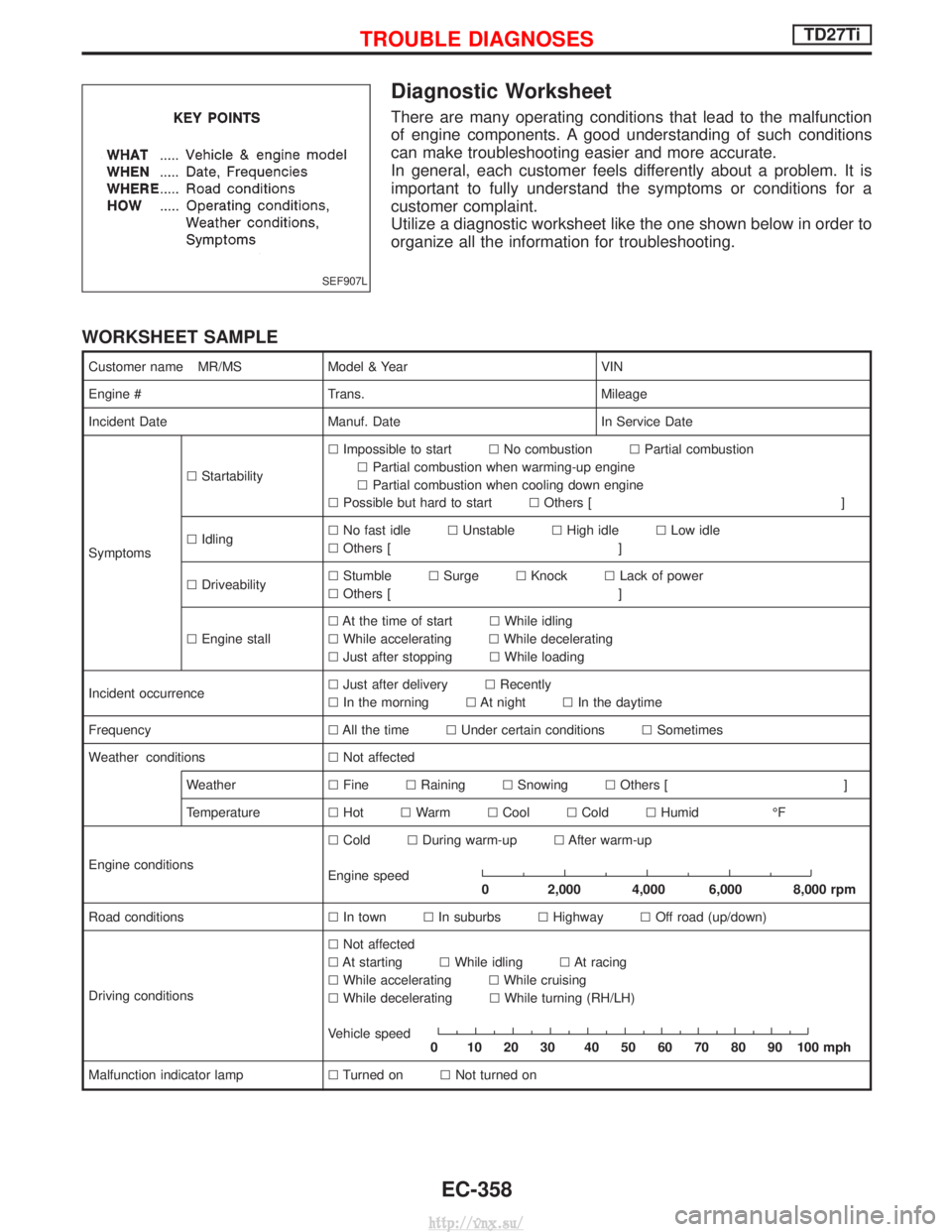
Diagnostic Worksheet
There are many operating conditions that lead to the malfunction
of engine components. A good understanding of such conditions
can make troubleshooting easier and more accurate.
In general, each customer feels differently about a problem. It is
important to fully understand the symptoms or conditions for a
customer complaint.
Utilize a diagnostic worksheet like the one shown below in order to
organize all the information for troubleshooting.
WORKSHEET SAMPLE
Customer name MR/MSModel & Year VIN
Engine # Trans. Mileage
Incident Date Manuf. Date In Service Date
Symptoms l
Startability l
Impossible to start lNo combustion lPartial combustion
l Partial combustion when warming-up engine
l Partial combustion when cooling down engine
l Possible but hard to start lOthers [ ]
l Idling l
No fast idle lUnstable lHigh idle lLow idle
l Others [ ]
l Driveability l
Stumble lSurge lKnock lLack of power
l Others [ ]
l Engine stall l
At the time of start lWhile idling
l While accelerating lWhile decelerating
l Just after stopping lWhile loading
Incident occurrence l
Just after delivery lRecently
l In the morning lAt night lIn the daytime
Frequency lAll the time lUnder certain conditions lSometimes
Weather conditions lNot affected
Weather lFine lRaining lSnowing lOthers [ ]
Temperature lHot lWarm lCool lCold lHumid ÉF
Engine conditions l
Cold lDuring warm-up lAfter warm-up
Engine speed
0 2,000 4,000 6,000 8,000 rpm
Road conditions lIn town lIn suburbs lHighway lOff road (up/down)
Driving conditions l
Not affected
l At starting lWhile idling lAt racing
l While accelerating lWhile cruising
l While decelerating lWhile turning (RH/LH)
Vehicle speed
0 102030 405060708090100mph
Malfunction indicator lamp lTurned on lNot turned on
SEF907L
TROUBLE DIAGNOSESTD27Ti
EC-358
http://vnx.su/
Page 636 of 1833

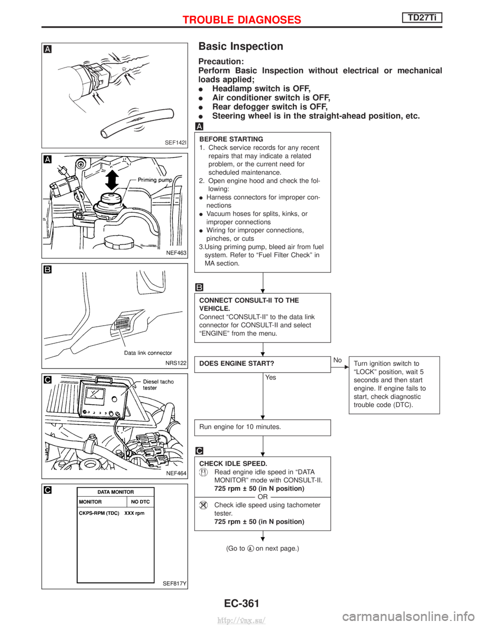
Basic Inspection
Precaution:
Perform Basic Inspection without electrical or mechanical
loads applied;
IHeadlamp switch is OFF,
I Air conditioner switch is OFF,
I Rear defogger switch is OFF,
I Steering wheel is in the straight-ahead position, etc.
BEFORE STARTING
1. Check service records for any recent
repairs that may indicate a related
problem, or the current need for
scheduled maintenance.
2. Open engine hood and check the fol- lowing:
I Harness connectors for improper con-
nections
I Vacuum hoses for splits, kinks, or
improper connections
I Wiring for improper connections,
pinches, or cuts
3.Using priming pump, bleed air from fuel system. Refer to ªFuel Filter Checkº in
MA section.
CONNECT CONSULT-II TO THE
VEHICLE.
Connect ªCONSULT-IIº to the data link
connector for CONSULT-II and select
ªENGINEº from the menu.
DOES ENGINE START?
Ye s
ENo Turn ignition switch to
ªLOCKº position, wait 5
seconds and then start
engine. If engine fails to
start, check diagnostic
trouble code (DTC).
Run engine for 10 minutes.
CHECK IDLE SPEED.
Read engine idle speed in ªDATA
MONITORº mode with CONSULT-II.
725 rpm 50 (in N position)
----------------------------------------------------------------------------------------------------------------------------------- -OR------------------------------------------------------------------------------------------------------------------------------------
Check idle speed using tachometer
tester.
725 rpm 50 (in N position)
(Go to qAon next page.)
SEF142I
NEF463
NRS122
NEF464
SEF817Y
H
H
H
H
H
TROUBLE DIAGNOSESTD27Ti
EC-361
http://vnx.su/
Page 672 of 1833

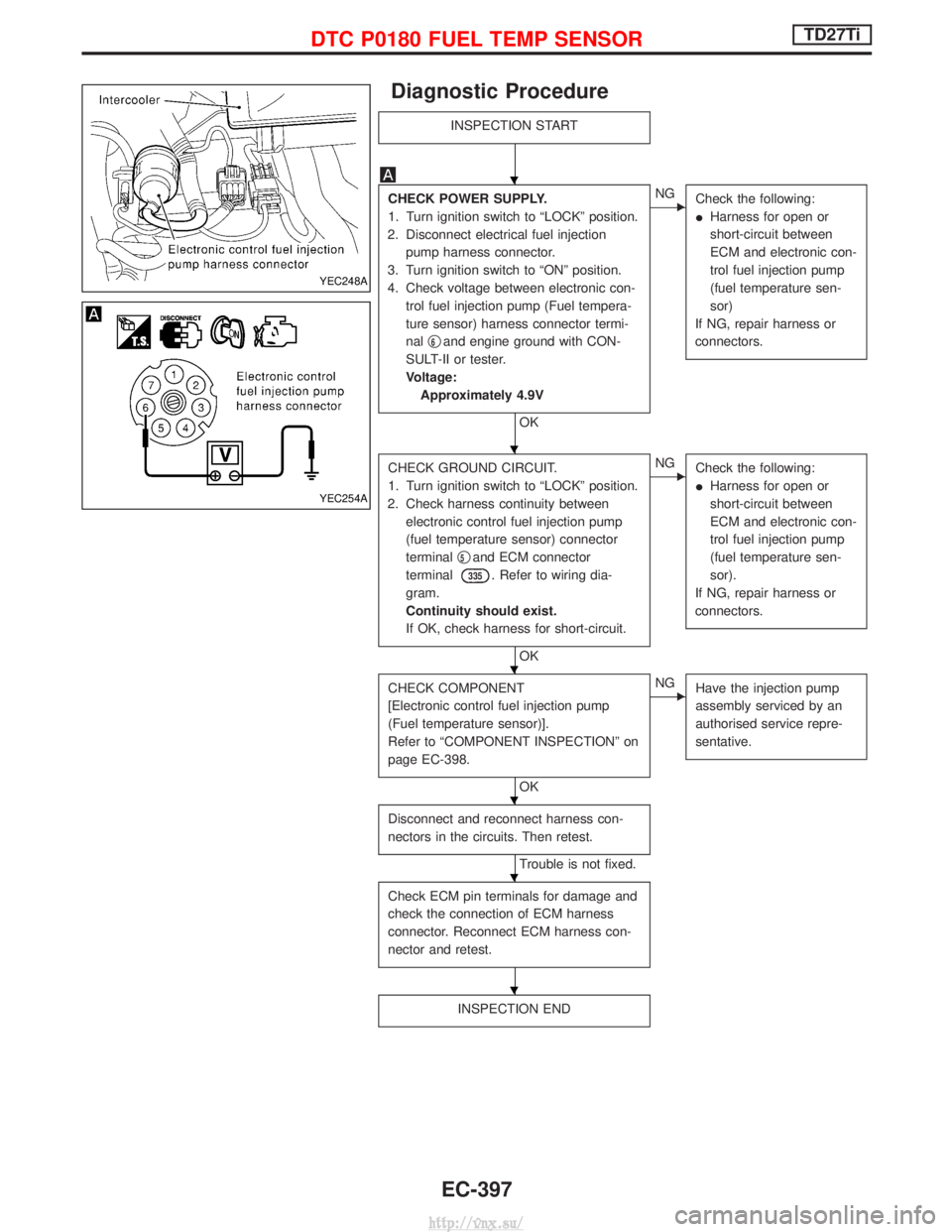
Diagnostic Procedure
INSPECTION START
CHECK POWER SUPPLY.
1. Turn ignition switch to ªLOCKº position.
2. Disconnect electrical fuel injection pump harness connector.
3. Turn ignition switch to ªONº position.
4. Check voltage between electronic con- trol fuel injection pump (Fuel tempera-
ture sensor) harness connector termi-
nal q
6and engine ground with CON-
SULT-II or tester.
Voltage: Approximately 4.9V
OK
ENG Check the following:
IHarness for open or
short-circuit between
ECM and electronic con-
trol fuel injection pump
(fuel temperature sen-
sor)
If NG, repair harness or
connectors.
CHECK GROUND CIRCUIT.
1. Turn ignition switch to ªLOCKº position.
2. Check harness continuity between electronic control fuel injection pump
(fuel temperature sensor) connector
terminal q
5and ECM connector
terminal
335. Refer to wiring dia-
gram.
Continuity should exist.
If OK, check harness for short-circuit.
OK
ENG Check the following:
IHarness for open or
short-circuit between
ECM and electronic con-
trol fuel injection pump
(fuel temperature sen-
sor).
If NG, repair harness or
connectors.
CHECK COMPONENT
[Electronic control fuel injection pump
(Fuel temperature sensor)].
Refer to ªCOMPONENT INSPECTIONº on
page EC-398.
OK
ENG Have the injection pump
assembly serviced by an
authorised service repre-
sentative.
Disconnect and reconnect harness con-
nectors in the circuits. Then retest.
Trouble is not fixed.
Check ECM pin terminals for damage and
check the connection of ECM harness
connector. Reconnect ECM harness con-
nector and retest.
INSPECTION END
YEC248A
YEC254A
H
H
H
H
H
H
DTC P0180 FUEL TEMP SENSORTD27Ti
EC-397
http://vnx.su/
Page 673 of 1833
Component Inspection
ELECTRONIC CONTROL FUEL INJECTION PUMP (FUEL
TEMPERATURE SENSOR)
Wait until fuel temperature sensor reaches room temperature.
Check resistance between electronic control fuel injection pump
(fuel temperature sensor) terminalsq
5andq6.
Temperature ÉC (ÉF)
Resistance kW
25 (77) Approximately 1.9
If NG, have the injection pump assembly serviced by an authorised
service representative.
YEC255A
DTC P0180 FUEL TEMP SENSORTD27Ti
EC-398
http://vnx.su/