Page 839 of 1833

Work Flow
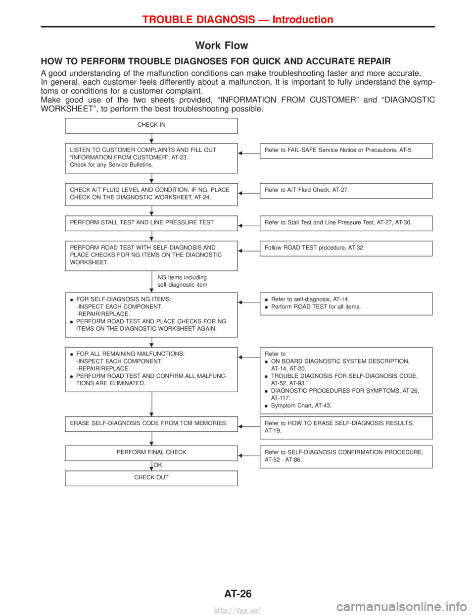
HOW TO PERFORM TROUBLE DIAGNOSES FOR QUICK AND ACCURATE REPAIR
A good understanding of the malfunction conditions can make troubleshooting faster and more accurate.
In general, each customer feels differently about a malfunction. It is important to fully understand the symp-
toms or conditions for a customer complaint.
Make good use of the two sheets provided, ªINFORMATION FROM CUSTOMERº and ªDIAGNOSTIC
WORKSHEETº, to perform the best troubleshooting possible.
CHECK IN
LISTEN TO CUSTOMER COMPLAINTS AND FILL OUT
ªINFORMATION FROM CUSTOMERº, AT-23.
Check for any Service Bulletins.FRefer to FAIL-SAFE Service Notice or Precautions, AT-5.
CHECK A/T FLUID LEVEL AND CONDITION. IF NG, PLACE
CHECK ON THE DIAGNOSTIC WORKSHEET, AT-24.FRefer to A/T Fluid Check, AT-27.
PERFORM STALL TEST AND LINE PRESSURE TEST.FRefer to Stall Test and Line Pressure Test, AT-27, AT-30.
PERFORM ROAD TEST WITH SELF-DIAGNOSIS AND
PLACE CHECKS FOR NG ITEMS ON THE DIAGNOSTIC
WORKSHEET.
NG items including
self-diagnostic item
FFollow ROAD TEST procedure, AT-32.
IFOR SELF-DIAGNOSIS NG ITEMS:
-INSPECT EACH COMPONENT.
-REPAIR/REPLACE.
I PERFORM ROAD TEST AND PLACE CHECKS FOR NG
ITEMS ON THE DIAGNOSTIC WORKSHEET AGAIN.FIRefer to self-diagnosis, AT-14.
I Perform ROAD TEST for all items.
IFOR ALL REMAINING MALFUNCTIONS:
-INSPECT EACH COMPONENT.
-REPAIR/REPLACE.
I PERFORM ROAD TEST AND CONFIRM ALL MALFUNC-
TIONS ARE ELIMINATED.FRefer to
ION BOARD DIAGNOSTIC SYSTEM DESCRIPTION,
AT-14, AT-20.
I TROUBLE DIAGNOSIS FOR SELF-DIAGNOSIS CODE,
AT-52, AT-93.
I DIAGNOSTIC PROCEDURES FOR SYMPTOMS, AT-26,
AT-117.
I Symptom Chart, AT-43.
ERASE SELF-DIAGNOSIS CODE FROM TCM MEMORIES.FRefer to HOW TO ERASE SELF-DIAGNOSIS RESULTS,
AT-19.
PERFORM FINAL CHECK
OK
FRefer to SELF-DIAGNOSIS CONFIRMATION PROCEDURE,
AT-52 - AT-86.
CHECK OUT
H
H
H
H
H
H
H
H
H
TROUBLE DIAGNOSIS Ð Introduction
AT-26
http://vnx.su/
Page 931 of 1833
Control Valve Assembly and Accumulators
REMOVAL
1. Remove exhaust front tube.
2. Remove oil pan and gasket and drain ATF.
3. Remove A/T fluid temperature sensor if necessary.
4. Remove oil strainer.
5. Remove control valve assembly by removing fixing bolts anddisconnecting harness connector.
Bolt length and location
Bolt symbol mm (in)
qA33 (1.30)
q
B45 (1.77)
6. Remove solenoids and valves from valve body if necessary.
7. Remove terminal cord assembly if necessary.
8. Remove accumulator q
A,qB,qCand qDby applying com-
pressed air if necessary.
I Hold each piston with rag.
9. Reinstall any part removed.
I Always use new sealing parts.
NAT277
SAT073BA
SAT353B
SAT074BA
ON-VEHICLE SERVICE
AT-118
http://vnx.su/
Page 932 of 1833

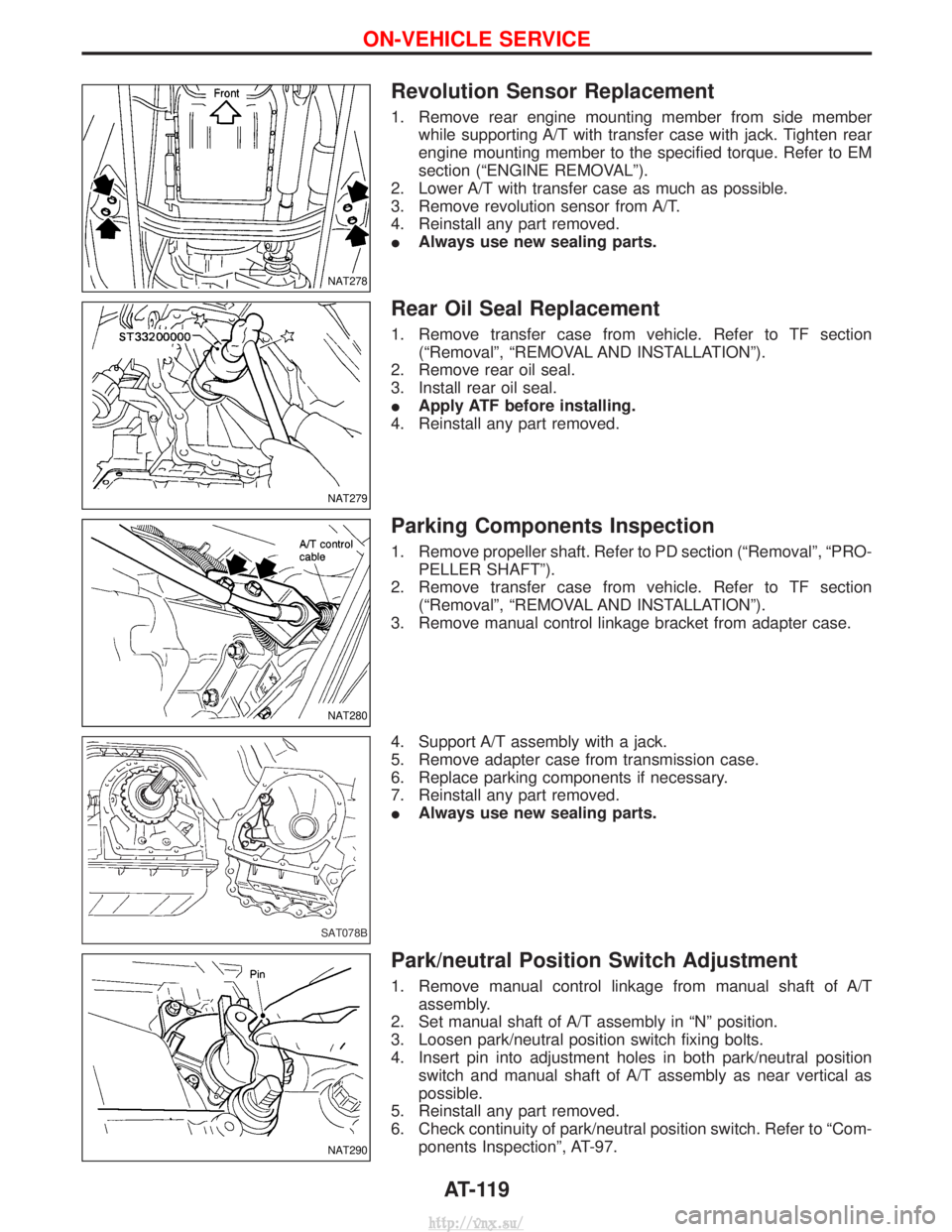
Revolution Sensor Replacement
1. Remove rear engine mounting member from side memberwhile supporting A/T with transfer case with jack. Tighten rear
engine mounting member to the specified torque. Refer to EM
section (ªENGINE REMOVALº).
2. Lower A/T with transfer case as much as possible.
3. Remove revolution sensor from A/T.
4. Reinstall any part removed.
I Always use new sealing parts.
Rear Oil Seal Replacement
1. Remove transfer case from vehicle. Refer to TF section
(ªRemovalº, ªREMOVAL AND INSTALLATIONº).
2. Remove rear oil seal.
3. Install rear oil seal.
I Apply ATF before installing.
4. Reinstall any part removed.
Parking Components Inspection
1. Remove propeller shaft. Refer to PD section (ªRemovalº, ªPRO- PELLER SHAFTº).
2. Remove transfer case from vehicle. Refer to TF section (ªRemovalº, ªREMOVAL AND INSTALLATIONº).
3. Remove manual control linkage bracket from adapter case.
4. Support A/T assembly with a jack.
5. Remove adapter case from transmission case.
6. Replace parking components if necessary.
7. Reinstall any part removed.
I Always use new sealing parts.
Park/neutral Position Switch Adjustment
1. Remove manual control linkage from manual shaft of A/T
assembly.
2. Set manual shaft of A/T assembly in ªNº position.
3. Loosen park/neutral position switch fixing bolts.
4. Insert pin into adjustment holes in both park/neutral position switch and manual shaft of A/T assembly as near vertical as
possible.
5. Reinstall any part removed.
6. Check continuity of park/neutral position switch. Refer to ªCom- ponents Inspectionº, AT-97.
NAT278
NAT279
NAT280
SAT078B
NAT290
ON-VEHICLE SERVICE
AT-119
http://vnx.su/
Page 933 of 1833
Manual Control Linkage Adjustment
Move selector lever from ªPº position to ª1º position. You should be
able to feel the detents in each position.
If the detents cannot be felt or the pointer indicating the position is
improperly aligned, the linkage needs adjustment.
1. Place selector lever in ªPº position.
2. Loosen lock nuts.
3. Tighten turn buckle until aligns with inner cable, pulling selec-tor lever toward ªRº position side without pushing button.
4. Back off turn buckle 1 turn and tighten lock nuts to the speci- fied torque.Lock nut
: 4.4 - 5.9 N ×m
(0.45 - 0.60 kg-m, 39.1 - 52.1 in-lb)
5. Move selector lever from ªPº position to ª1º position. Make sure that selector lever can move smoothly.
NAT282
NAT283
ON-VEHICLE SERVICE
AT-120
http://vnx.su/
Page 973 of 1833
High Clutch
DISASSEMBLY AND ASSEMBLY
Service procedures for high clutch are essentially the same as
those for reverse clutch, with the following exception:
ICheck of high clutch operation
NAT299
SAT853A
SAT854A
REPAIR FOR COMPONENT PARTS
AT-160
http://vnx.su/
Page 976 of 1833
DISASSEMBLY AND ASSEMBLY
Forward and overrun clutches are serviced essentially the same
way as reverse clutch is serviced. However, note the following
exceptions.
ICheck of forward clutch operation.
I Check of overrun clutch operation.
I Removal of forward clutch drum
Remove forward clutch drum from transmission case by hold-
ing snap ring.
I Removal of forward clutch and overrun clutch pistons
1. While holding overrun clutch piston, gradually apply com- pressed air to oil hole.
2. Remove overrun clutch from forward clutch.
SAT860A
SAT861A
SAT865A
SAT862A
SAT863A
REPAIR FOR COMPONENT PARTS
Forward and Overrun Clutches (Cont'd)
AT-163
http://vnx.su/
Page 1014 of 1833

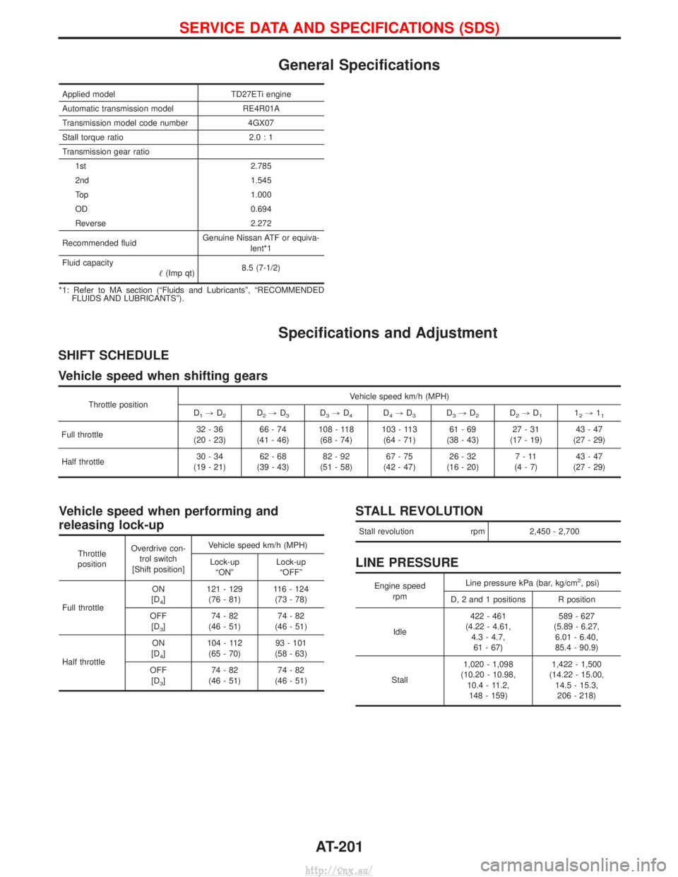
General Specifications
Applied modelTD27ETi engine
Automatic transmission model RE4R01A
Transmission model code number 4GX07
Stall torque ratio 2.0 : 1
Transmission gear ratio 1st 2.785
2nd 1.545
Top 1.000
OD 0.694
Reverse 2.272
Recommended fluid Genuine Nissan ATF or equiva-
lent*1
Fluid capacity (Imp qt) 8.5 (7-1/2)
*1: Refer to MA section (ªFluids and Lubricantsº, ªRECOMMENDED FLUIDS AND LUBRICANTSº).
Specifications and Adjustment
SHIFT SCHEDULE
Vehicle speed when shifting gears
Throttle position Vehicle speed km/h (MPH)
D1, D2D2,D3D3,D4D4,D3D3,D2D2,D112,11
Full throttle 32-36
(20 - 23) 66-74
(41 - 46) 108 - 118
(68 - 74) 103 - 113
(64 - 71) 61-69
(38 - 43) 27-31
(17 - 19) 43-47
(27 - 29)
Half throttle 30-34
(19 - 21) 62-68
(39 - 43) 82-92
(51 - 58) 67-75
(42 - 47) 26-32
(16 - 20) 7-11
(4-7) 43-47
(27 - 29)
Vehicle speed when performing and
releasing lock-up
Throttle
position Overdrive con-
trol switch
[Shift position] Vehicle speed km/h (MPH)
Lock-up ªONº Lock-up
ªOFFº
Full throttle ON
[D
4] 121 - 129
(76 - 81) 116 - 124
(73 - 78)
OFF [D
3] 74-82
(46 - 51) 74-82
(46 - 51)
Half throttle ON
[D
4] 104 - 112
(65 - 70) 93 - 101
(58 - 63)
OFF [D
3] 74-82
(46 - 51) 74-82
(46 - 51)
STALL REVOLUTION
Stall revolution rpm2,450 - 2,700
LINE PRESSURE
Engine speed
rpm Line pressure kPa (bar, kg/cm2, psi)
D, 2 and 1 positions R position
Idle 422 - 461
(4.22 - 4.61, 4.3 - 4.7,61 - 67) 589 - 627
(5.89 - 6.27, 6.01 - 6.40,
85.4 - 90.9)
Stall 1,020 - 1,098
(10.20 - 10.98, 10.4 - 11.2,148 - 159) 1,422 - 1,500
(14.22 - 15.00, 14.5 - 15.3,206 - 218)
SERVICE DATA AND SPECIFICATIONS (SDS)
AT-201
http://vnx.su/
Page 1015 of 1833

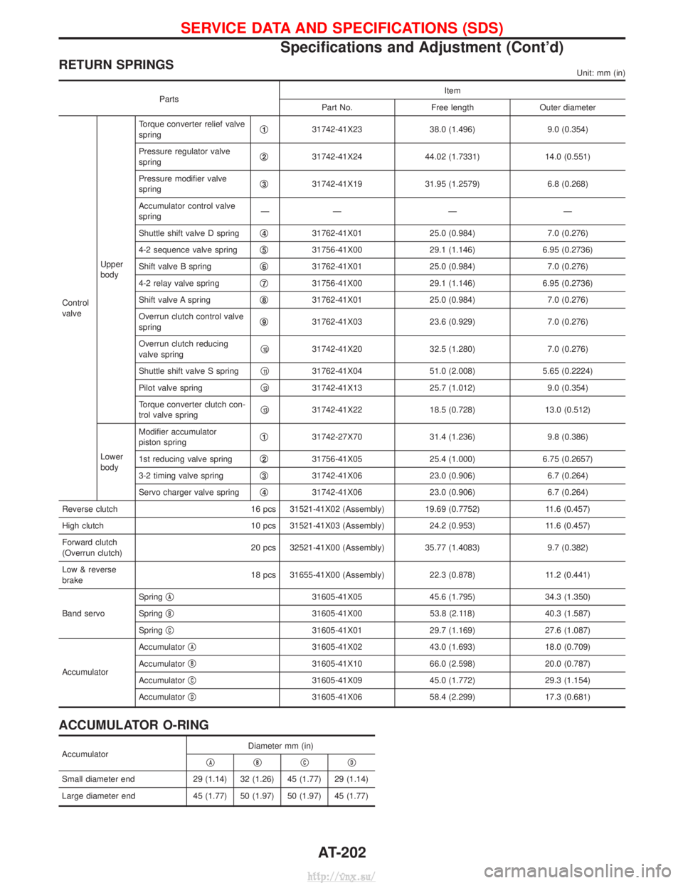
RETURN SPRINGSUnit: mm (in)
PartsItem
Part No. Free length Outer diameter
Control
valve Upper
bodyTorque converter relief valve
spring
q
131742-41X23
38.0 (1.496)9.0 (0.354)
Pressure regulator valve
spring q
231742-41X24
44.02 (1.7331) 14.0 (0.551)
Pressure modifier valve
spring q
331742-41X19
31.95 (1.2579) 6.8 (0.268)
Accumulator control valve
spring ÐÐÐÐ
Shuttle shift valve D spring q
431762-41X01
25.0 (0.984)7.0 (0.276)
4-2 sequence valve spring q
531756-41X00
29.1 (1.146)6.95 (0.2736)
Shift valve B spring q
631762-41X01
25.0 (0.984)7.0 (0.276)
4-2 relay valve spring q
731756-41X00
29.1 (1.146)6.95 (0.2736)
Shift valve A spring q
831762-41X01
25.0 (0.984)7.0 (0.276)
Overrun clutch control valve
spring q
931762-41X03
23.6 (0.929)7.0 (0.276)
Overrun clutch reducing
valve spring q
1031742-41X20
32.5 (1.280)7.0 (0.276)
Shuttle shift valve S spring q
1131762-41X04
51.0 (2.008)5.65 (0.2224)
Pilot valve spring q
1231742-41X13
25.7 (1.012)9.0 (0.354)
Torque converter clutch con-
trol valve spring q
1331742-41X22
18.5 (0.728)13.0 (0.512)
Lower
body Modifier accumulator
piston spring
q
131742-27X70
31.4 (1.236)9.8 (0.386)
1st reducing valve spring q
231756-41X05
25.4 (1.000)6.75 (0.2657)
3-2 timing valve spring q
331742-41X06
23.0 (0.906)6.7 (0.264)
Servo charger valve spring q
431742-41X06
23.0 (0.906)6.7 (0.264)
Reverse clutch 16 pcs 31521-41X02 (Assembly) 19.69 (0.7752) 11.6 (0.457)
High clutch 10 pcs 31521-41X03 (Assembly)24.2 (0.953)11.6 (0.457)
Forward clutch
(Overrun clutch) 20 pcs 32521-41X00 (Assembly) 35.77 (1.4083)
9.7 (0.382)
Low & reverse
brake 18 pcs 31655-41X00 (Assembly)
22.3 (0.878)11.2 (0.441)
Band servo Spring
q
A31605-41X05
45.6 (1.795)34.3 (1.350)
Spring q
B31605-41X00
53.8 (2.118)40.3 (1.587)
Spring q
C31605-41X01
29.7 (1.169)27.6 (1.087)
Accumulator Accumulator
q
A31605-41X02
43.0 (1.693)18.0 (0.709)
Accumulator q
B31605-41X10
66.0 (2.598)20.0 (0.787)
Accumulator q
C31605-41X09
45.0 (1.772)29.3 (1.154)
Accumulator q
D31605-41X06
58.4 (2.299)17.3 (0.681)
ACCUMULATOR O-RING
Accumulator Diameter mm (in)
qAqBqCqD
Small diameter end 29 (1.14) 32 (1.26) 45 (1.77) 29 (1.14)
Large diameter end 45 (1.77) 50 (1.97) 50 (1.97) 45 (1.77)
SERVICE DATA AND SPECIFICATIONS (SDS)
Specifications and Adjustment (Cont'd)
AT-202
http://vnx.su/