Page 1050 of 1833

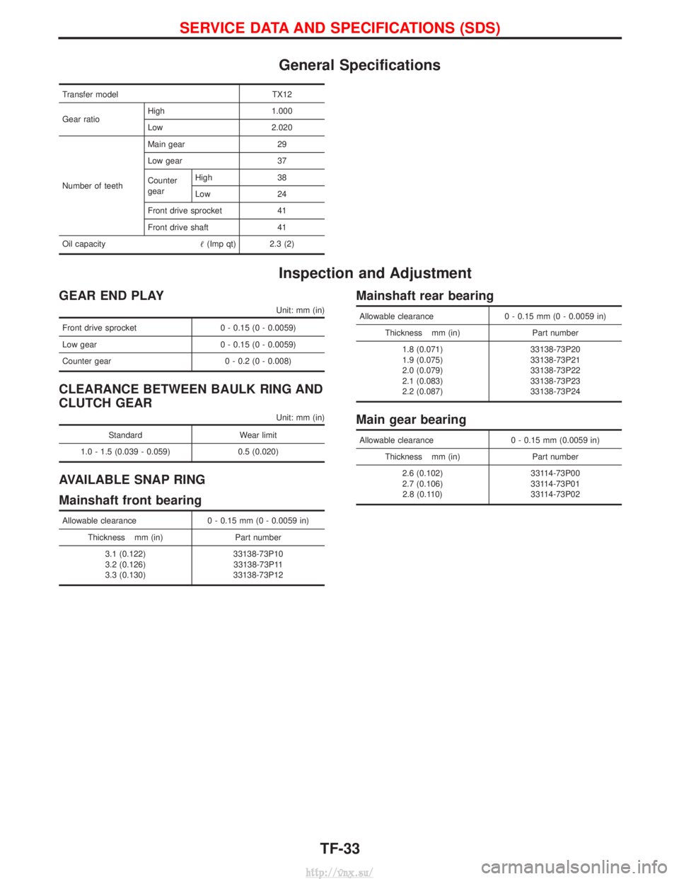
General Specifications
Transfer modelTX12
Gear ratio High 1.000
Low 2.020
Number of teeth Main gear 29
Low gear 37
Counter
gear
High 38
Low 24
Front drive sprocket 41
Front drive shaft 41
Oil capacity (Imp qt) 2.3 (2)
Inspection and Adjustment
GEAR END PLAY
Unit: mm (in)
Front drive sprocket 0 - 0.15 (0 - 0.0059)
Low gear 0 - 0.15 (0 - 0.0059)
Counter gear 0 - 0.2 (0 - 0.008)
CLEARANCE BETWEEN BAULK RING AND
CLUTCH GEAR
Unit: mm (in)
Standard Wear limit
1.0 - 1.5 (0.039 - 0.059) 0.5 (0.020)
AVAILABLE SNAP RING
Mainshaft front bearing
Allowable clearance0 - 0.15 mm (0 - 0.0059 in)
Thickness mm (in) Part number
3.1 (0.122)
3.2 (0.126)
3.3 (0.130) 33138-73P10
33138-73P11
33138-73P12
Mainshaft rear bearing
Allowable clearance 0 - 0.15 mm (0 - 0.0059 in)
Thickness mm (in) Part number
1.8 (0.071)
1.9 (0.075)
2.0 (0.079)
2.1 (0.083)
2.2 (0.087) 33138-73P20
33138-73P21
33138-73P22
33138-73P23
33138-73P24
Main gear bearing
Allowable clearance
0 - 0.15 mm (0.0059 in)
Thickness mm (in) Part number
2.6 (0.102)
2.7 (0.106) 2.8 (0.110) 33114-73P00
33114-73P01
33114-73P02
SERVICE DATA AND SPECIFICATIONS (SDS)
TF-33
http://vnx.su/
Page 1051 of 1833
AVAILABLE SHIMCounter gear rear bearing
Distance ªAº mm (in) Shim(s)
Thickness mm (in) Part number
32.65 - 32.55
(1.2854 - 1.2815) Not necessary
32.55 - 32.45
(1.2815 - 1.2776) 0.1 (0.004)
33112-C6900
32.45 - 32.35
(1.2776 - 1.2736) 0.2 (0.008)
33112-C6901
32.35 - 32.25
(1.2736 - 1.2697) 0.3 (0.012)
33112-C6902
32.25 - 32.15
(1.2697 - 1.2657) 0.4 (0.016)
33112-C6903
32.15 - 32.05
(1.2657 - 1.2618) 0.5 (0.020)
33112-33G00
32.05 - 31.95
(1.2618 - 1.2579) 0.6 (0.024)
33112-33G01
SMT335A
SERVICE DATA AND SPECIFICATIONS (SDS)
Inspection and Adjustment (Cont'd)
TF-34
http://vnx.su/
Page 1052 of 1833

PROPELLER SHAFT &
DIFFERENTIAL CARRIER
SECTION
PD
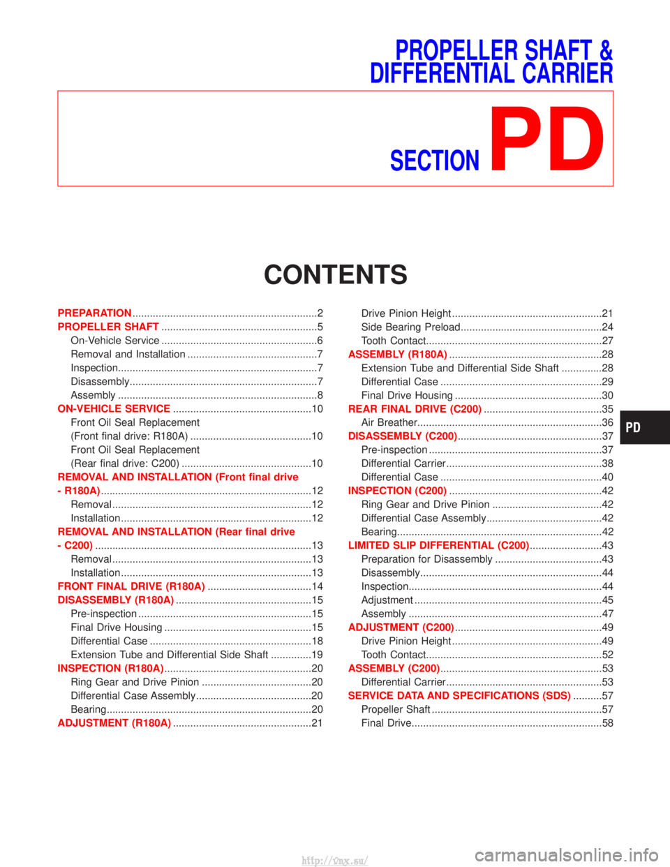
CONTENTS
PREPARATION ................................................................2
PROPELLER SHAFT ......................................................5
On-Vehicle Service ......................................................6
Removal and Installation .............................................7
Inspection.....................................................................7
Disassembly.................................................................7
Assembly .....................................................................8
ON-VEHICLE SERVICE ................................................10
Front Oil Seal Replacement
(Front final drive: R180A) ..........................................10
Front Oil Seal Replacement
(Rear final drive: C200) .............................................10
REMOVAL AND INSTALLATION (Front final drive
- R180A) ........................................................................\
.12
Removal .....................................................................12
Installation ..................................................................12
REMOVAL AND INSTALLATION (Rear final drive
- C200) ........................................................................\
...13
Removal .....................................................................13
Installation ..................................................................13
FRONT FINAL DRIVE (R180A) ....................................14
DISASSEMBLY (R180A) ...............................................15
Pre-inspection ............................................................15
Final Drive Housing ...................................................15
Differential Case ........................................................18
Extension Tube and Differential Side Shaft ..............19
INSPECTION (R180A) ...................................................20
Ring Gear and Drive Pinion ......................................20
Differential Case Assembly........................................20
Bearing.......................................................................20
ADJUSTMENT (R180A) ................................................21 Drive Pinion Height ....................................................21
Side Bearing Preload.................................................24
Tooth Contact.............................................................27
ASSEMBLY (R180A) .....................................................28
Extension Tube and Differential Side Shaft ..............28
Differential Case ........................................................29
Final Drive Housing ...................................................30
REAR FINAL DRIVE (C200) .........................................35
Air Breather................................................................36
DISASSEMBLY (C200) ..................................................37
Pre-inspection ............................................................37
Differential Carrier......................................................38
Differential Case ........................................................40
INSPECTION (C200) .....................................................42
Ring Gear and Drive Pinion ......................................42
Differential Case Assembly........................................42
Bearing.......................................................................42
LIMITED SLIP DIFFERENTIAL (C200) .........................43
Preparation for Disassembly .....................................43
Disassembly...............................................................44
Inspection...................................................................44
Adjustment .................................................................45
Assembly ...................................................................47
ADJUSTMENT (C200) ...................................................49
Drive Pinion Height ....................................................49
Tooth Contact.............................................................52
ASSEMBLY (C200) ........................................................53
Differential Carrier......................................................53
SERVICE DATA AND SPECIFICATIONS (SDS) ..........57
Propeller Shaft ...........................................................57
Final Drive..................................................................58
http://vnx.su/
Page 1053 of 1833
SPECIAL SERVICE TOOLS
*: Special tool or commercial equivalent
Tool number
Tool nameDescription Unit application
R180A H233B
ST31211000
Height gauge
Selecting pinion height adjusting washer
XÐ
ST31212000
Dummy shaft
Selecting pinion height adjusting washer XÐ
ST31852000
Stopper
Selecting pinion height adjusting washer XÐ
ST3125S000
Drive pinion height
setting gauge set
q
1ST31251000
Drive pinion
height gauge
q
2ST31181001
Dummy shaft
Selecting pinion height adjusting washer
ÐX
ST32501000
Weight block
Selecting side bearing adjusting shim XÐ
KV38101900
Master gauge
[20.0 mm (0.787 in)]
Selecting side bearing adjusting shim XÐ
ST0501S000
Engine stand
q
1ST05011000
Engine stand
q
2ST05012000
Base
Mounting differential attachment
XX
KV38100800
Differential attach-
ment
Mounting final drive XÐ
ST06340000
Differential attach-
ment
Mounting final drive ÐX
PREPARATION
PD-2
http://vnx.su/
Page 1057 of 1833

On-Vehicle Service
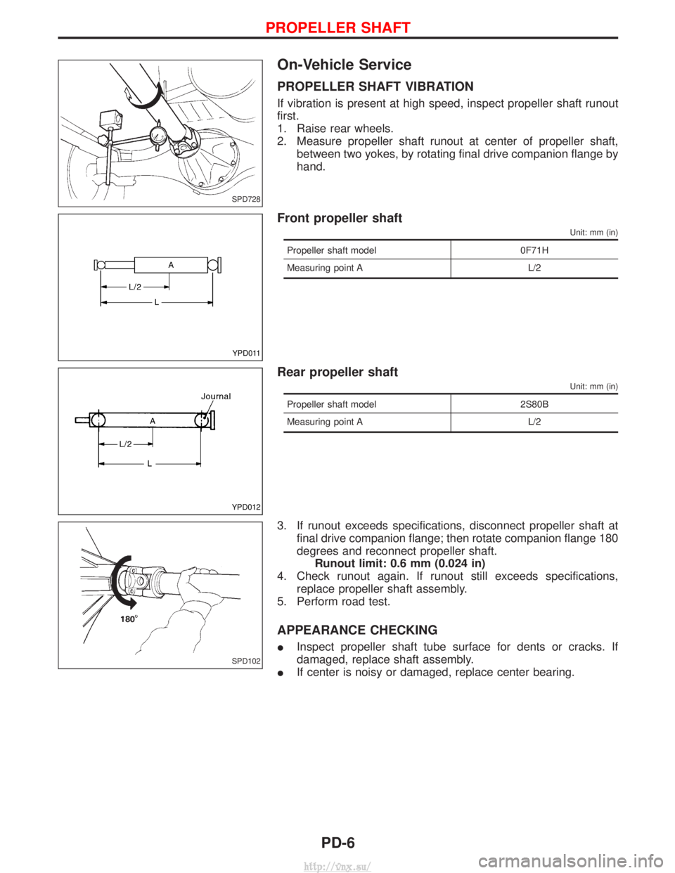
PROPELLER SHAFT VIBRATION
If vibration is present at high speed, inspect propeller shaft runout
first.
1. Raise rear wheels.
2. Measure propeller shaft runout at center of propeller shaft,between two yokes, by rotating final drive companion flange by
hand.
Front propeller shaft
Unit: mm (in)
Propeller shaft model 0F71H
Measuring point A L/2
Rear propeller shaft
Unit: mm (in)
Propeller shaft model 2S80B
Measuring point A L/2
3. If runout exceeds specifications, disconnect propeller shaft at
final drive companion flange; then rotate companion flange 180
degrees and reconnect propeller shaft.Runout limit: 0.6 mm (0.024 in)
4. Check runout again. If runout still exceeds specifications, replace propeller shaft assembly.
5. Perform road test.
APPEARANCE CHECKING
I Inspect propeller shaft tube surface for dents or cracks. If
damaged, replace shaft assembly.
I If center is noisy or damaged, replace center bearing.
SPD728
YPD011
YPD012
SPD102
PROPELLER SHAFT
PD-6
http://vnx.su/
Page 1061 of 1833
Front Oil Seal Replacement
(Front final drive: R180A)
1. Remove front propeller shaft.
2. Loosen drive pinion nut.Tool number: ST38060002
3. Remove companion flange.
4. Remove front oil seal.
5. Apply multi-purpose grease to cavity at sealing lips of oil seal. Press front oil seal into carrier.
6. Install companion flange and drive pinion nut.
7. Install propeller shaft. Tool number:ST30720000
Front Oil Seal Replacement
(Rear final drive: C200)
1. Remove rear propeller shaft.
2. Loosen drive pinion nut. Tool number:KV38104700
SPD733
SPD734
SPD735
SPD736
PD237
ON-VEHICLE SERVICE
PD-10
http://vnx.su/
Page 1062 of 1833
3. Remove companion flange.
4. Remove front oil seal.
5. Apply multi-purpose grease to cavity at sealing lips of oil seal.Press front oil seal into carrier.
6. Install companion flange and drive pinion nut in.
7. Install rear propeller shaft. Tool number:KV381025S0
SPD737
SPD738
SPD739
ON-VEHICLE SERVICE
Front Oil Seal Replacement
(Rear final drive: C200) (Cont'd)
PD-11
http://vnx.su/
Page 1108 of 1833

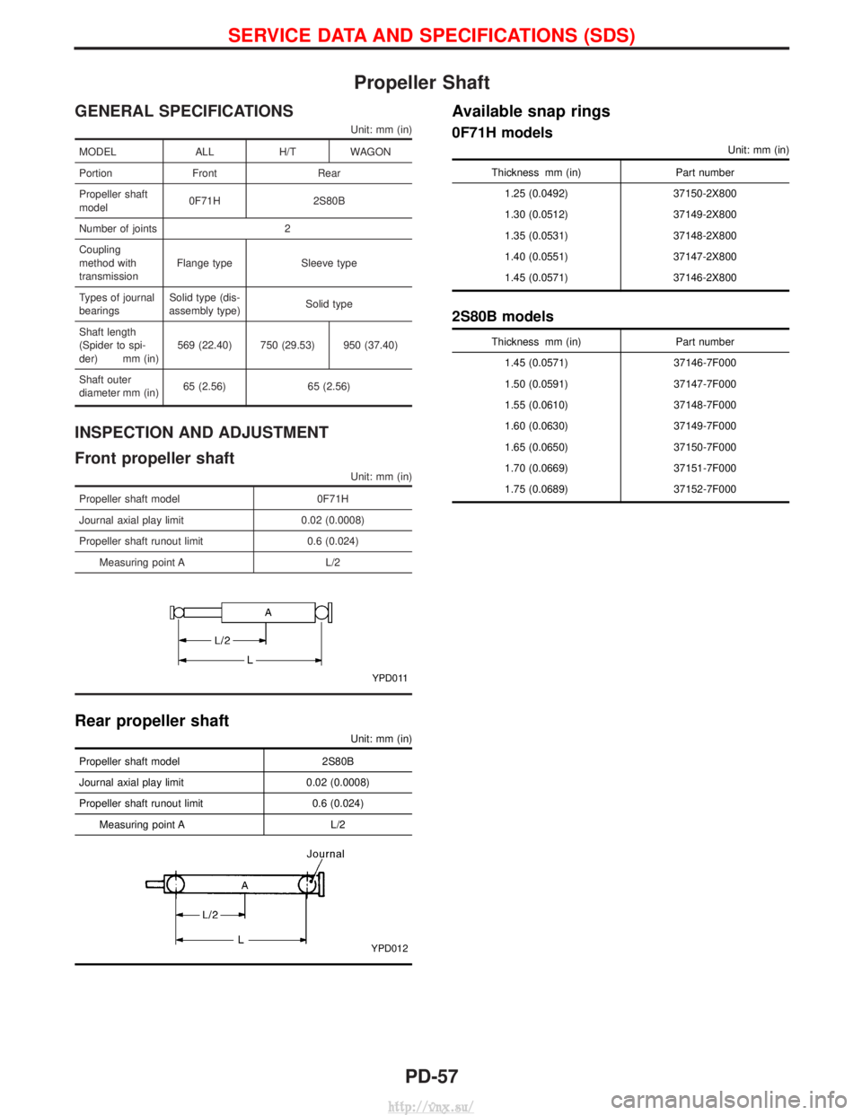
Propeller Shaft
GENERAL SPECIFICATIONS
Unit: mm (in)
MODELALLH/TWAGON
Portion Front Rear
Propeller shaft
model 0F71H 2S80B
Number of joints 2
Coupling
method with
transmission Flange type Sleeve type
Types of journal
bearings Solid type (dis-
assembly type) Solid type
Shaft length
(Spider to spi-
der) mm (in) 569 (22.40) 750 (29.53) 950 (37.40)
Shaft outer
diameter mm (in) 65 (2.56) 65 (2.56)
INSPECTION AND ADJUSTMENT
Front propeller shaft
Unit: mm (in)
Propeller shaft model
0F71H
Journal axial play limit 0.02 (0.0008)
Propeller shaft runout limit 0.6 (0.024)
Measuring point A L/2
YPD011
Rear propeller shaft
Unit: mm (in)
Propeller shaft model 2S80B
Journal axial play limit 0.02 (0.0008)
Propeller shaft runout limit 0.6 (0.024) Measuring point A L/2
YPD012
Available snap rings
0F71H models
Unit: mm (in)
Thickness mm (in) Part number
1.25 (0.0492) 37150-2X800
1.30 (0.0512) 37149-2X800
1.35 (0.0531) 37148-2X800
1.40 (0.0551) 37147-2X800
1.45 (0.0571) 37146-2X800
2S80B models
Thickness mm (in) Part number
1.45 (0.0571) 37146-7F000
1.50 (0.0591) 37147-7F000
1.55 (0.0610) 37148-7F000
1.60 (0.0630) 37149-7F000
1.65 (0.0650) 37150-7F000
1.70 (0.0669) 37151-7F000
1.75 (0.0689) 37152-7F000
SERVICE DATA AND SPECIFICATIONS (SDS)
PD-57
http://vnx.su/