2004 NISSAN TERRANO service
[x] Cancel search: servicePage 1275 of 1833
General Specifications
ModelsAll
Steering gear type ZF 8054
Turns of steering
wheel
(Lock to lock) 3.86
Overall gear ratio 17.1 : 1
Steering column type Collapsible, adjustable height
Inspection and Adjustment
STEERING WHEEL AND COLUMN
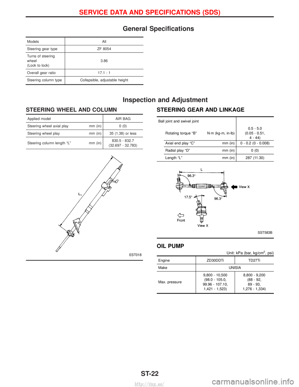
Applied model AIR BAG
Steering wheel axial play mm (in) 0 (0)
Steering wheel play mm (in) 35 (1.38) or less
Steering column length ªLº mm (in) 830.5 - 832.7
(32.697 - 32.783)
EST018
STEERING GEAR AND LINKAGE
Ball joint and swivel joint
Rotating torque ªBº N×m (kg-m, in-lb) 0.5 - 5.0
(0.05 - 0.51, 4 - 44)
Axial end play ªCº mm (in) 0 - 0.2 (0 - 0.008)
Radial play ªDº mm (in) 0 (0)
Length ªLº mm (in) 287 (11.30)
SST583B
OIL PUMP
Unit: kPa (bar, kg/cm2, psi)
EngineZD30DDTiTD27Ti
Make UNISIA
Max. pressure 9,800 - 10,500
(98.0 - 105.0,
99.96 - 107.10, 1,421 - 1,523) 8,800 - 9,200
(88 - 92,89 - 93,
1,276 - 1,334)
SERVICE DATA AND SPECIFICATIONS (SDS)
ST-22
http://vnx.su/
Page 1277 of 1833
Precautions
SUPPLEMENTAL RESTRAINT SYSTEM (SRS) ªAIR BAGº AND ªSEAT BELT
PRE-TENSIONERº
The Supplemental Restraint System such as ªAIR BAGº and ªSEAT BELT PRE-TENSIONERº used along with
a seat belt, helps to reduce the risk or severity of injury to the driver and front passenger for certain types of
collision. The SRS composition which is available to NISSAN MODEL R20 is as follows (The composition
varies according to the destination and optional equipment.):
IFor a frontal collision
The Supplemental Restraint System consists of driver air bag module (located in the center of the steer-
ing wheel), front passenger air bag module (located on the instrument panel on passenger side), front seat
belt pre-tensioners, a diagnosis sensor unit, warning lamp, wiring harness and spiral cable.
I For a side collision
The Supplemental Restraint System consists of front side air bag module (located in the outer side of front
seat), side air bag (satellite) sensor, diagnosis sensor unit (one of components of air bags for a frontal
collision), wiring harness, warning lamp (one of components of air bags for a frontal collision).
WARNING:
I To avoid rendering the SRS inoperative, which could increase the risk of personal injury or death
in the event of a collision which would result in air bag inflation, all maintenance should be per-
formed by an authorized NISSAN dealer.
I Improper maintenance, including incorrect removal and installation of the SRS, can lead to per-
sonal injury caused by unintentional activation of the system.
I Do not use electrical test equipment on any circuit related to the SRS unless instructed to in this
Service Manual. Spiral cable and wiring harnesses covered with yellow insulation tape either just
before the harness connectors or for the complete harness are related to the SRS.
Precaution for Seat Belt Service
CAUTION:
IBefore removing the seat belt pre-tensioner assembly, turn the ignition switch off, disconnect both
battery cables and wait at least 3 minutes.
I Do not use electrical test equipment for seat belt pre-tensioner connector.
I After replacing or reinstalling seat belt pre-tensioner assembly, or reconnecting seat belt pre-ten-
sioner connector, check the system function. Refer to ªSRS Operation Checkº for details. (RS-38)
I Do not disassemble buckle or seat belt assembly.
I Replace anchor bolts if they are deformed or worn out.
I Never oil tongue and buckle.
I If any component of seat belt assembly is questionable, do not repair. Replace the whole seat belt
assembly.
I If webbing is cut, frayed, or damaged, replace seat belt assembly.
I When replacing seat belt assembly, use a genuine seat belt assembly.
After A Collision
WARNING:
Inspect all seat belt assemblies including retractors and attaching hardware after any collision.
NISSAN recommends that all seat belt assemblies in use during a collision be replaced unless the
collision was minor and the belts show no damage and continue to operate properly. Failure to do so
could result in serious personal injury in an accident. Seat belt assemblies not in use during a colli-
sion should also be replaced if either damage or improper operation is noted. Seat belt pre-tensioner
should be replaced even if the seat belts are not in use during a frontal collision in which the air bags
are deployed.
Replace any seat belt assembly if:
IThe seat belt was in use at the time of a collision (except for minor collisions and the belts, retractors and
buckles show no damage and continue to operate properly).
I The seat belt was damaged in an accident. (i.e. torn webbing, bent retractor or guide, etc.)
I The seat belt attaching point was damaged in an accident. Inspect the seat belt attaching area for dam-
age or distortion and repair as necessary before installing a new seat belt assembly.
I Anchor bolts are deformed or worn out.
SEAT BELTS
RS-2
http://vnx.su/
Page 1283 of 1833
Precautions
SUPPLEMENTAL RESTRAINT SYSTEM (SRS) ªAIR BAGº AND ªSEAT BELT
PRE-TENSIONERº
The Supplemental Restraint System such as ªAIR BAGº and ªSEAT BELT PRE-TENSIONERº used along with
a seat belt, helps to reduce the risk or severity of injury to the driver and front passenger for certain types of
collision. The SRS composition which is available to NISSAN MODEL R20 is as follows (The composition
varies according to the destination and optional equipment.):
IFor a frontal collision
The Supplemental Restraint System consists of driver air bag module (located in the center of the steer-
ing wheel), front passenger air bag module (located on the instrument panel on passenger side), front seat
belt pre-tensioners, a diagnosis sensor unit, warning lamp, wiring harness and spiral cable.
I For a side collision
The Supplemental Restraint System consists of front side air bag module (located in the outer side of front
seat), side air bag (satellite) sensor, diagnosis sensor unit (one of components of air bags for a frontal
collision), wiring harness, warning lamp (one of components of air bags for a frontal collision).
WARNING:
I To avoid rendering the SRS inoperative, which could increase the risk of personal injury or death
in the event of a collision which would result in air bag inflation, all maintenance should be per-
formed by an authorized NISSAN dealer.
I Improper maintenance, including incorrect removal and installation of the SRS, can lead to per-
sonal injury caused by unintentional activation of the system.
I Do not use electrical test equipment on any circuit related to the SRS unless instructed to in this
Service Manual. Spiral cable and wiring harnesses covered with yellow insulation tape either just
before the harness connectors or for the complete harness are related to the SRS.
PRECAUTIONS FOR SRS ªAIR BAGº AND ªSEAT BELT PRE-TENSIONERº SERVICE
IDo not use electrical test equipment to check SRS circuits unless instructed to in this Service Manual.
I Before servicing the SRS, turn ignition switch ªOFFº, disconnect both battery cables and wait at least 3
minutes.
For approximately 3 minutes after the cables are removed, it is still possible for the air bag and seat belt
pre-tensioner to deploy. Therefore, do not work on any SRS connectors or wires until at least 3 minutes
have passed.
I Diagnosis sensor unit must always be installed with their arrow marks ª +º pointing towards the front of
the vehicle for proper operation. Also check diagnosis sensor unit for cracks, deformities or rust before
installation and replace as required.
I The spiral cable must be aligned with the neutral position since its rotations are limited. Do not attempt to
turn steering wheel or column after removal of steering gear.
I Handle air bag module carefully. Always place driver and front passenger air bag modules with the pad
side facing upward and place front side air bag module (built-in type) standing with stud bolt side setting
bottom.
I Conduct self-diagnosis to check entire SRS for proper function after replacing any components.
I After air bag inflates, the front instrument panel assembly should be replaced if damaged.
WIRING DIAGRAMS AND TROUBLE DIAGNOSIS
When you read wiring diagrams, refer to the following:
IGI-10, ªHOW TO READ WIRING DIAGRAMSº
I EL-8, ªPOWER SUPPLY ROUTINGº for power distribution circuit
When you perform trouble diagnosis, refer to the following:
I GI-25, ªHOW TO FOLLOW TEST GROUPS IN TROUBLE DIAGNOSISº
I GI-22, ªHOW TO PERFORM EFFICIENT DIAGNOSES FOR AN ELECTRICAL INCIDENTº
SUPPLEMENTAL RESTRAINT SYSTEM (SRS)
RS-8
http://vnx.su/
Page 1284 of 1833
Preparation
SPECIAL SERVICE TOOLS
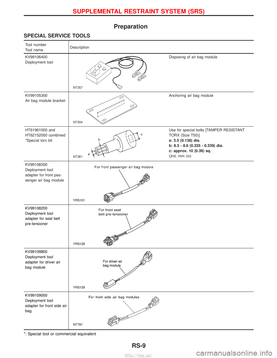
Tool number
Tool nameDescription
KV99106400
Deployment tool
NT357
Disposing of air bag module
KV99105300
Air bag module bracket
NT354
Anchoring air bag module
HT61961000 and
HT62152000 combined
*Special torx bit
NT361
Use for special bolts [TAMPER RESISTANT
TORX (Size T50)]
a: 3.5 (0.138) dia.
b: 8.5 - 8.6 (0.335 - 0.339) dia.
c: approx. 10 (0.39) sq.
Unit: mm (in)
KV99108300
Deployment tool
adapter for front pas-
senger air bag module
YRS101
KV99108200
Deployment tool
adapter for seat belt
pre-tensioner
YRS128
KV99109800
Deployment tool
adapter for driver air
bag module
YRS129
KV99109000
Deployment tool
adapter for front side air
bag
NT797
*: Special tool or commercial equivalent
SUPPLEMENTAL RESTRAINT SYSTEM (SRS)
RS-9
http://vnx.su/
Page 1285 of 1833
COMMERCIAL SERVICE TOOL
Tool nameDescription
Tamper resistant torx
socket
NT757
Size: T30
SRS Configuration
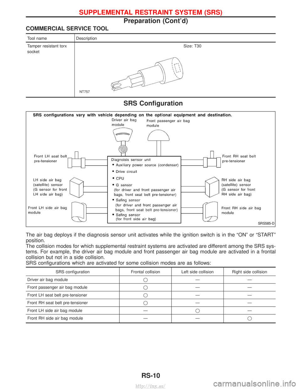
The air bag deploys if the diagnosis sensor unit activates while the ignition switch is in the ªONº or ªSTARTº
position.
The collision modes for which supplemental restraint systems are activated are different among the SRS sys-
tems. For example, the driver air bag module and front passenger air bag module are activated in a frontal
collision but not in a side collision.
SRS configurations which are activated for some collision modes are as follows:
SRS configuration Frontal collisionLeft side collision Right side collision
Driver air bag module qÐÐ
Front passenger air bag module qÐÐ
Front LH seat belt pre-tensioner qÐÐ
Front RH seat belt pre-tensioner qÐÐ
Front LH side air bag module Ð qÐ
Front RH side air bag module Ð Ð q
SRS585-D
SUPPLEMENTAL RESTRAINT SYSTEM (SRS)
Preparation (Cont'd)
RS-10
http://vnx.su/
Page 1297 of 1833
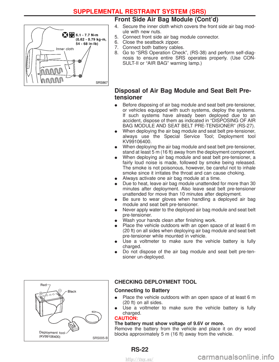
4. Secure the inner cloth which covers the front side air bag mod-ule with new nuts.
5. Connect front side air bag module connector.
6. Close the seatback zipper.
7. Connect both battery cables.
8. Go to ªSRS Operation Checkº, (RS-38) and perform self-diag- nosis to ensure entire SRS operates properly. (Use CON-
SULT-II or ªAIR BAGº warning lamp.)
Disposal of Air Bag Module and Seat Belt Pre-
tensioner
IBefore disposing of air bag module and seat belt pre-tensioner,
or vehicles equipped with such systems, deploy the systems.
If such systems have already been deployed due to an
accident, dispose of them as indicated in ªDISPOSING OF AIR
BAG MODULE AND SEAT BELT PRE-TENSIONERº (RS-27).
I When deploying the air bag module and seat belt pre-tensioner,
always use the Special Service Tool; Deployment tool
KV99106400.
I When deploying the air bag module and seat belt pre-tensioner,
stand at least 5 m (16 ft) away from the deployment component.
I When deploying air bag module and seat belt pre-tensioner, a
fairly loud noise is made, followed by smoke being released.
The smoke is not poisonous, however, be careful not to inhale
smoke since it irritates the throat and can cause choking.
I Always activate one air bag module at a time.
I Due to heat, leave air bag module unattended for more than 30
minutes after deployment. Also leave seat belt pre-tensioner
unattended for move than 10 minutes after deployment.
I Be sure to wear gloves when handling a deployed air bag
module and seat belt pre-tensioner.
I Never apply water to the deployed air bag module and seat belt
pre-tensioner.
I Wash your hands clean after finishing work.
I Place the vehicle outdoors with an open space of at least 6 m
(20 ft) on all sides when deploying air bag module and seat belt
pre-tensioner while mounted in vehicle.
I Use a voltmeter to make sure the vehicle battery is fully
charged.
I Do not dispose of the air bag module and seat belt pre-ten-
sioner un-deployed.
CHECKING DEPLOYMENT TOOL
Connecting to Battery
IPlace the vehicle outdoors with an open space of at least 6 m
(20 ft) on all sides.
I Use a voltmeter to make sure the vehicle battery is fully
charged.
CAUTION:
The battery must show voltage of 9.6V or more.
Remove the battery from the vehicle and place it on dry wood
blocks approximately 5 m (16 ft) away from the vehicle.
SRS867
SRS005-B
SUPPLEMENTAL RESTRAINT SYSTEM (SRS)
Front Side Air Bag Module (Cont'd)
RS-22
http://vnx.su/
Page 1303 of 1833
Trouble Diagnoses Introduction
CAUTION:
IDo not use electrical test equipment on any circuit related to the SRS unless instructed to in this
Service Manual. Spiral cable and wiring harnesses covered with yellow insulation tape either just
before the harness connectors or for the complete harness are related to the SRS.
I Do not attempt to repair, splice or modify the SRS wiring harness. If the harness is damaged,
replace it with a new one.
I Keep ground portion clean.
DIAGNOSIS FUNCTION
The SRS self-diagnosis results can be read by using ªAIR BAGº warning lamp and/or CONSULT-II. The read-
ing of these results is accomplished using one of two modes Ð ªUser modeº and ªDiagnosis modeº.
The User mode is exclusively prepared for the customer (driver). This mode warns the driver of a system
malfunction through the operation of the ªAIR BAGº warning lamp.
The Diagnosis mode allows the technician to locate and inspect the malfunctioning part.
The mode applications for the ªAIR BAGº warning lamp and CONSULT-II are as follows:
User mode Diagnosis mode Display type
ªAIR BAGº warning lamp X X ON-OFF operation
CONSULT-II Ð X Monitoring
NOTE:
Seat belt pre-tensioner malfunction is indicated by ªAIR BAGº warning lamp.
DIAGNOSIS MODE FOR CONSULT-II
I ªSELF-DIAG [CURRENT]º
A current self-diagnosis result (also indicated by the number of warning lamp flashes in the Diagnosis
mode) is displayed on the CONSULT-II screen in real time. This refers to a malfunctioning part requiring
repairs.
I ªSELF-DIAG [PAST]º
Diagnosis results previously stored in the memory are displayed on the CONSULT-II screen. The stored
results are not erased until memory erasing is executed.
I ªTROUBLE DIAG RECORDº
With TROUBLE DIAG RECORD, diagnosis results previously erased by a reset operation can be displayed
on the CONSULT-II screen.
I ªECU DISCRIMINATED NO.º
The diagnosis sensor unit for each vehicle model is assigned with its own, individual classification num-
ber (refer to the table below). This number will be displayed on the CONSULT-II screen. When replacing
the diagnosis sensor unit, refer to the part number for the compatibility. After installation, replacement with
a correct unit can be checked by confirming this classification number on the CONSULT-II screen.
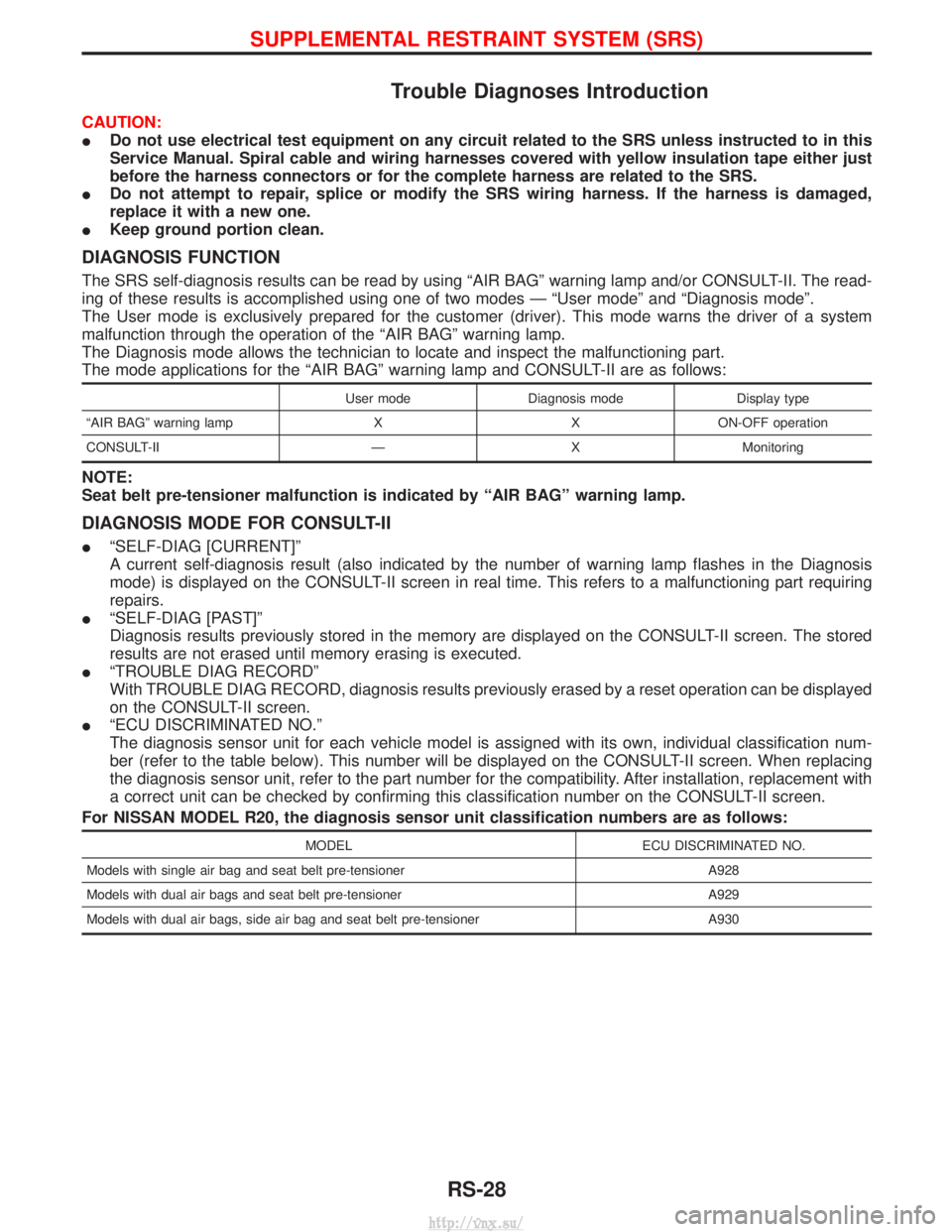
For NISSAN MODEL R20, the diagnosis sensor unit classification numbers are as follows:
MODEL ECU DISCRIMINATED NO.
Models with single air bag and seat belt pre-tensioner A928
Models with dual air bags and seat belt pre-tensioner A929
Models with dual air bags, side air bag and seat belt pre-tensioner A930
SUPPLEMENTAL RESTRAINT SYSTEM (SRS)
RS-28
http://vnx.su/
Page 1338 of 1833
BODY & TRIM
SECTION
BT
CONTENTS
PRECAUTIONS ...............................................................2
Service Notice..............................................................2
Supplemental Restraint System (SRS) ²AIR
BAG² and²SEAT BELT PRE-TENSIONER² ...............2
CLIP AND FASTENER ....................................................3
Description ...................................................................3
CHASSIS AND BODY MAINTENANCE .........................5
Checking Body Corrosion ............................................5
BODY FRONT END .........................................................6
Removal and Installation .............................................6
BODY REAR END AND OPENER ..................................8
Removal and Installation .............................................8
DOOR ........................................................................\
.....10
Removal and Installation ...........................................10
INSTRUMENT PANEL ASSEMBLY ..............................16
Removal and Installation ...........................................16
SIDE AND FLOOR TRIM ..............................................18
Removal and Installation ...........................................18
DOOR TRIM ...................................................................19
Removal and Installation ...........................................19 ROOF TRIM
...................................................................20
Removal and Installation ...........................................20
EXTERIOR .....................................................................21
Removal and Installation ...........................................21
FRONT SEAT .................................................................34
Removal and Installation ...........................................34
Heated Seat ...............................................................36
Active Head Restraint ................................................36
SECOND SEAT ..............................................................37
Removal and Installation ...........................................37
THIRD SEAT ..................................................................39
Removal and Installation ...........................................39
SUNROOF ......................................................................40
Removal and Installation ...........................................40
WINDSHIELD AND WINDOWS ....................................42
Removal and Installation ...........................................42
DOOR MIRROR .............................................................48
Removal and Installation ...........................................48
BODY (ALIGNMENT) ....................................................49
Alignment ...................................................................49
http://vnx.su/