2004 NISSAN TERRANO service
[x] Cancel search: servicePage 1571 of 1833
Trouble Diagnoses
SYMPTOM CHART
SymptomDiagnoses service procedure
Interior room lamp timer does not operate. 1. Preliminary check.
2. Check ignition signal.
3. Check driver side door switch.
4. Check door lock/unlock switch.
5. Check other door switch.
Interior room lamp timer cannot be cancelled. 1. Preliminary check.
2. Check ignition signal.
3. Check driver side door switch.
4. Check door lock/unlock switch.
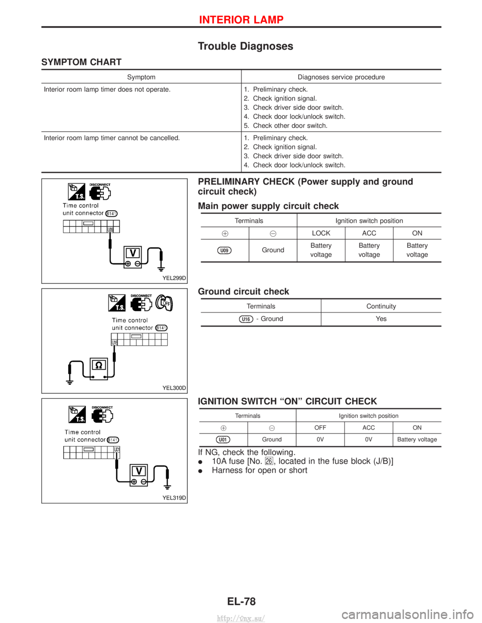
PRELIMINARY CHECK (Power supply and ground
circuit check)
Main power supply circuit check
Terminals Ignition switch position
!@ LOCK ACC ON
U09GroundBattery
voltage Battery
voltage Battery
voltage
Ground circuit check
Terminals Continuity
U16- GroundYes
IGNITION SWITCH ªONº CIRCUIT CHECK
TerminalsIgnition switch position
!@ OFFACC ON
U01Ground 0V0V Battery voltage
If NG, check the following.
I10A fuse [No.
26, located in the fuse block (J/B)]
IHarness for open or short
YEL299D
YEL300D
YEL319D
INTERIOR LAMP
EL-78
http://vnx.su/
Page 1583 of 1833

Combination Meter Self-Diagnosis
PERFORMING SELF-DIAGNOSIS MODE
1. Turn the ignition switch to the ªLOCKº position.
2. Press both reset buttons on the combination meter and keep them depressed.
3. Turn the ignition switch to the ªONº position, while keeping the reset buttons pressed.
4. Release both reset buttons within 5 seconds after ignition switch is ªONº, then self-diagnosis will start. Thesequence (A to I) is activated by press the either reset buttons.
NOTE:
If either reset button is not pressed for 20 seconds at each step or if the ignition switch is turned OFF, the
self-diagnosis mode is exited.
Check items Display Remarks
A) Odometer segment test All odo trip meter segments are ON.
B) Software code
NEL735
This information is not used for service. Please skip this
step.
C) EEPROM code
NEL736
This information is not used for service. Please skip this
step.
D) Hardware code
NEL737
This information is not used for service. Please skip this
step.
E) PCB code
NEL738
This information is not used for service. Please skip this
step.
F) Meter/gauge test
(Sweeping movement)
SEL440X
Tachometer, speedometer, fuel level gauge and water tem-
perature gauge have sweeping movement test.
(The meter/gauges operate MIN.
,MAX., MAX. ,MIN. for
2 times)
The odo trip meter segment flashes during the sweep move-
ment.
G) Error 1
(Bit 0 - Bit 3)
SEL441X
The segment of each bit displays ª0º, meaning no failure. If
the bit(s) displays figures other than ª0º, the item of the bit
has failed.
For details, refer to ªFailure chart for Error 1 and Error Eº
below.
H) Error E
(Bit 4 - Bit 7)
SEL442X
METER AND GAUGES
EL-90
http://vnx.su/
Page 1621 of 1833
Trouble Diagnoses
SYMPTOM CHART
SymptomDiagnoses service procedure
Rear window defogger and door mirror defogger do not activate. 1. Check time control unit power supply and ground circuit. 2. Check rear window defogger switch.
3. Check rear window defogger switch circuit.
4. Check rear window defogger signal.
5. Check rear window defogger relay.
Rear window defogger or door mirror defogger do not activate. 1. Check fuse (No. 14, No. 15 or No. 1). 2. Check filament.
3. Check harness between fuse block (J/B) and defogger.
4. Check defogger ground circuit.
Rear window defogger and door mirror defogger do not go off
after activating about 15 minutes. 1. Check time control unit power supply and ground circuit.
2. Check rear window defogger switch.
3. Check rear window defogger switch circuit.
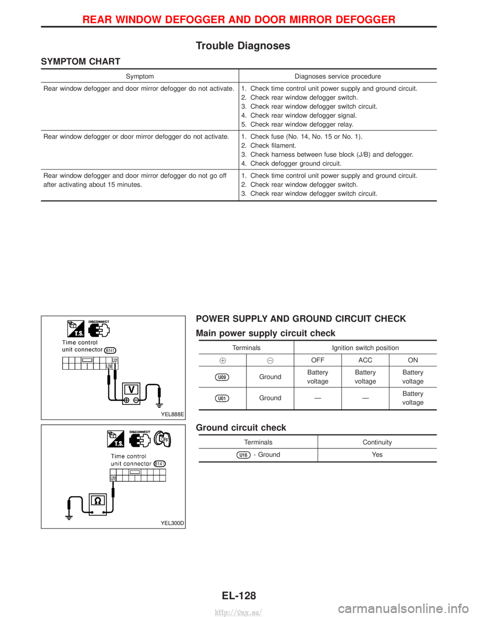
POWER SUPPLY AND GROUND CIRCUIT CHECK
Main power supply circuit check
Terminals
Ignition switch position
!@ OFF ACC ON
U09GroundBattery
voltage Battery
voltage Battery
voltage
U01Ground ÐÐBattery
voltage
Ground circuit check
Terminals Continuity
U16- GroundYes
YEL888E
YEL300D
REAR WINDOW DEFOGGER AND DOOR MIRROR DEFOGGER
EL-128
http://vnx.su/
Page 1627 of 1833
System Description
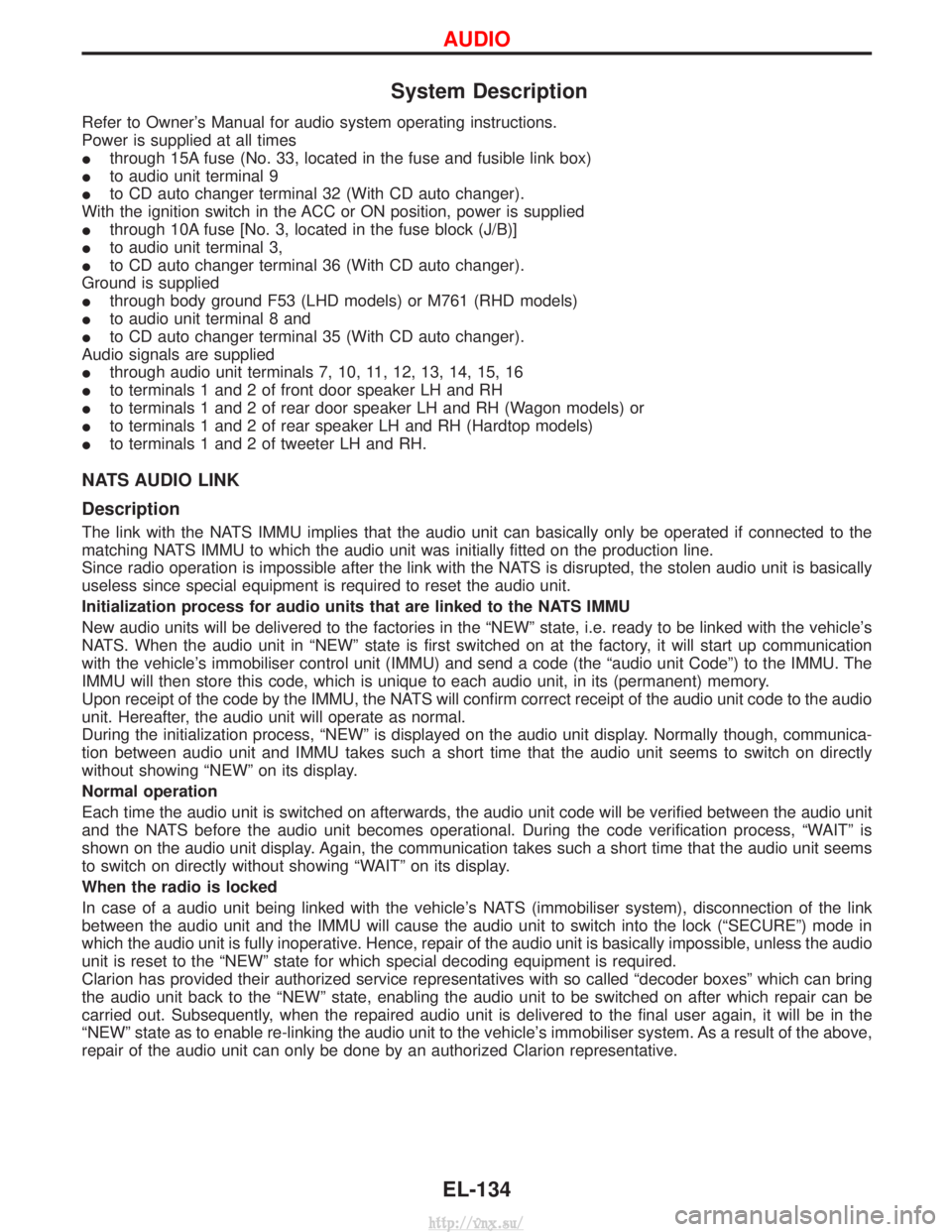
Refer to Owner's Manual for audio system operating instructions.
Power is supplied at all times
Ithrough 15A fuse (No. 33, located in the fuse and fusible link box)
I to audio unit terminal 9
I to CD auto changer terminal 32 (With CD auto changer).
With the ignition switch in the ACC or ON position, power is supplied
I through 10A fuse [No. 3, located in the fuse block (J/B)]
I to audio unit terminal 3,
I to CD auto changer terminal 36 (With CD auto changer).
Ground is supplied
I through body ground F53 (LHD models) or M761 (RHD models)
I to audio unit terminal 8 and
I to CD auto changer terminal 35 (With CD auto changer).
Audio signals are supplied
I through audio unit terminals 7, 10, 11, 12, 13, 14, 15, 16
I to terminals 1 and 2 of front door speaker LH and RH
I to terminals 1 and 2 of rear door speaker LH and RH (Wagon models) or
I to terminals 1 and 2 of rear speaker LH and RH (Hardtop models)
I to terminals 1 and 2 of tweeter LH and RH.
NATS AUDIO LINK
Description
The link with the NATS IMMU implies that the audio unit can basically only be operated if connected to the
matching NATS IMMU to which the audio unit was initially fitted on the production line.
Since radio operation is impossible after the link with the NATS is disrupted, the stolen audio unit is basically
useless since special equipment is required to reset the audio unit.
Initialization process for audio units that are linked to the NATS IMMU
New audio units will be delivered to the factories in the ªNEWº state, i.e. ready to be linked with the vehicle's
NATS. When the audio unit in ªNEWº state is first switched on at the factory, it will start up communication
with the vehicle's immobiliser control unit (IMMU) and send a code (the ªaudio unit Codeº) to the IMMU. The
IMMU will then store this code, which is unique to each audio unit, in its (permanent) memory.
Upon receipt of the code by the IMMU, the NATS will confirm correct receipt of the audio unit code to the audio
unit. Hereafter, the audio unit will operate as normal.
During the initialization process, ªNEWº is displayed on the audio unit display. Normally though, communica-
tion between audio unit and IMMU takes such a short time that the audio unit seems to switch on directly
without showing ªNEWº on its display.
Normal operation
Each time the audio unit is switched on afterwards, the audio unit code will be verified between the audio unit
and the NATS before the audio unit becomes operational. During the code verification process, ªWAITº is
shown on the audio unit display. Again, the communication takes such a short time that the audio unit seems
to switch on directly without showing ªWAITº on its display.
When the radio is locked
In case of a audio unit being linked with the vehicle's NATS (immobiliser system), disconnection of the link
between the audio unit and the IMMU will cause the audio unit to switch into the lock (ªSECUREº) mode in
which the audio unit is fully inoperative. Hence, repair of the audio unit is basically impossible, unless the audio
unit is reset to the ªNEWº state for which special decoding equipment is required.
Clarion has provided their authorized service representatives with so called ªdecoder boxesº which can bring
the audio unit back to the ªNEWº state, enabling the audio unit to be switched on after which repair can be
carried out. Subsequently, when the repaired audio unit is delivered to the final user again, it will be in the
ªNEWº state as to enable re-linking the audio unit to the vehicle's immobiliser system. As a result of the above,
repair of the audio unit can only be done by an authorized Clarion representative.
AUDIO
EL-134
http://vnx.su/
Page 1628 of 1833
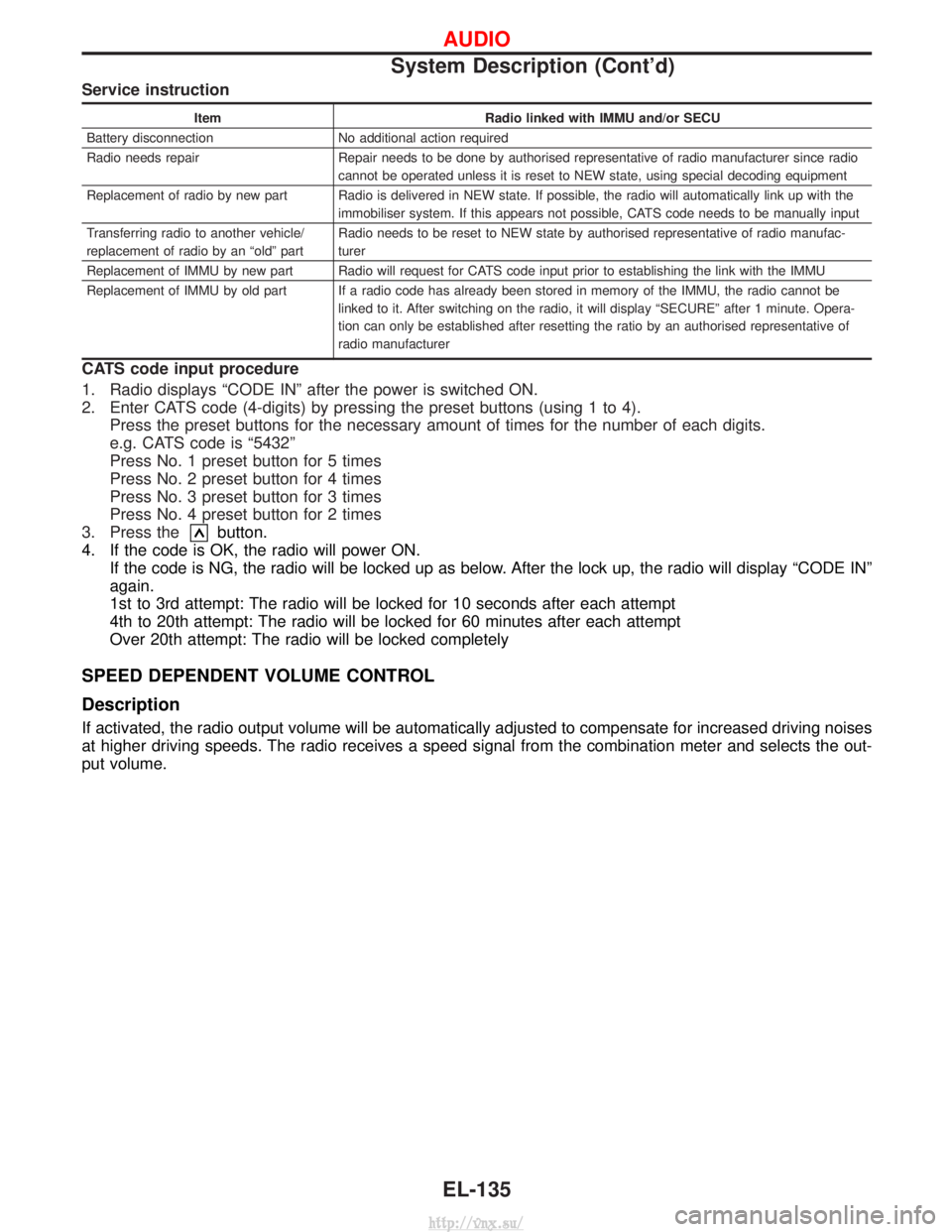
Service instruction
ItemRadio linked with IMMU and/or SECU
Battery disconnection No additional action required
Radio needs repair Repair needs to be done by authorised representative of radio manufacturer since radio cannot be operated unless it is reset to NEW state, using special decoding equipment
Replacement of radio by new part Radio is delivered in NEW state. If possible, the radio will automatically link up with the immobiliser system. If this appears not possible, CATS code needs to be manually input
Transferring radio to another vehicle/
replacement of radio by an ªoldº part Radio needs to be reset to NEW state by authorised representative of radio manufac-
turer
Replacement of IMMU by new part Radio will request for CATS code input prior to establishing the link with the IMMU
Replacement of IMMU by old part If a radio code has already been stored in memory of the IMMU, the radio cannot be linked to it. After switching on the radio, it will display ªSECUREº after 1 minute. Opera-
tion can only be established after resetting the ratio by an authorised representative of
radio manufacturer
CATS code input procedure
1. Radio displays ªCODE INº after the power is switched ON.
2. Enter CATS code (4-digits) by pressing the preset buttons (using 1 to 4).Press the preset buttons for the necessary amount of times for the number of each digits.
e.g. CATS code is ª5432º
Press No. 1 preset button for 5 times
Press No. 2 preset button for 4 times
Press No. 3 preset button for 3 times
Press No. 4 preset button for 2 times
3. Press the
button.
4. If the code is OK, the radio will power ON. If the code is NG, the radio will be locked up as below. After the lock up, the radio will display ªCODE INº
again.
1st to 3rd attempt: The radio will be locked for 10 seconds after each attempt
4th to 20th attempt: The radio will be locked for 60 minutes after each attempt
Over 20th attempt: The radio will be locked completely
SPEED DEPENDENT VOLUME CONTROL
Description
If activated, the radio output volume will be automatically adjusted to compensate for increased driving noises
at higher driving speeds. The radio receives a speed signal from the combination meter and selects the out-
put volume.
AUDIO
System Description (Cont'd)
EL-135
http://vnx.su/
Page 1706 of 1833
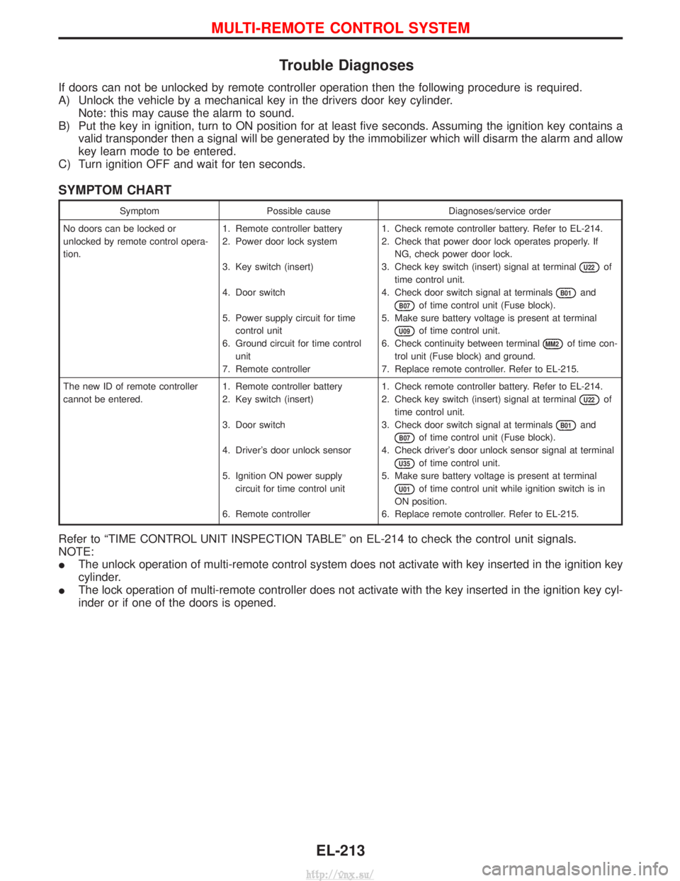
Trouble Diagnoses
If doors can not be unlocked by remote controller operation then the following procedure is required.
A) Unlock the vehicle by a mechanical key in the drivers door key cylinder.Note: this may cause the alarm to sound.
B) Put the key in ignition, turn to ON position for at least five seconds. Assuming the ignition key contains a valid transponder then a signal will be generated by the immobilizer which will disarm the alarm and allow
key learn mode to be entered.
C) Turn ignition OFF and wait for ten seconds.
SYMPTOM CHART
Symptom Possible cause Diagnoses/service order
No doors can be locked or
unlocked by remote control opera-
tion. 1. Remote controller battery
2. Power door lock system
3. Key switch (insert)
4. Door switch
5. Power supply circuit for time
control unit
6. Ground circuit for time control unit
7. Remote controller 1. Check remote controller battery. Refer to EL-214.
2. Check that power door lock operates properly. If
NG, check power door lock.
3. Check key switch (insert) signal at terminal
U22of
time control unit.
4. Check door switch signal at terminals
B01and
B07of time control unit (Fuse block).
5. Make sure battery voltage is present at terminal
U09of time control unit.
6. Check continuity between terminal
MM2of time con-
trol unit (Fuse block) and ground.
7. Replace remote controller. Refer to EL-215.
The new ID of remote controller
cannot be entered. 1. Remote controller battery
2. Key switch (insert)
3. Door switch
4. Driver's door unlock sensor
5. Ignition ON power supply
circuit for time control unit
6. Remote controller 1. Check remote controller battery. Refer to EL-214.
2. Check key switch (insert) signal at terminal
U22of
time control unit.
3. Check door switch signal at terminals
B01and
B07of time control unit (Fuse block).
4. Check driver's door unlock sensor signal at terminal
U35of time control unit.
5. Make sure battery voltage is present at terminal
U01of time control unit while ignition switch is in
ON position.
6. Replace remote controller. Refer to EL-215.
Refer to ªTIME CONTROL UNIT INSPECTION TABLEº on EL-214 to check the control unit signals.
NOTE:
I The unlock operation of multi-remote control system does not activate with key inserted in the ignition key
cylinder.
I The lock operation of multi-remote controller does not activate with the key inserted in the ignition key cyl-
inder or if one of the doors is opened.
MULTI-REMOTE CONTROL SYSTEM
EL-213
http://vnx.su/
Page 1711 of 1833
Trouble Diagnosis
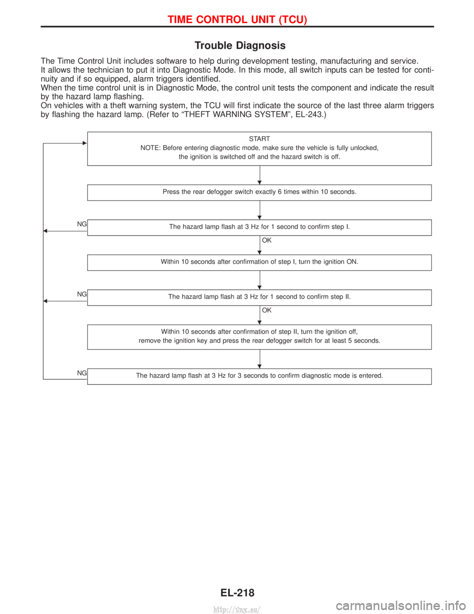
The Time Control Unit includes software to help during development testing, manufacturing and service.
It allows the technician to put it into Diagnostic Mode. In this mode, all switch inputs can be tested for conti-
nuity and if so equipped, alarm triggers identified.
When the time control unit is in Diagnostic Mode, the control unit tests the component and indicate the result
by the hazard lamp flashing.
On vehicles with a theft warning system, the TCU will first indicate the source of the last three alarm triggers
by flashing the hazard lamp. (Refer to ªTHEFT WARNING SYSTEMº, EL-243.)
ESTART
NOTE: Before entering diagnostic mode, make sure the vehicle is fully unlocked, the ignition is switched off and the hazard switch is off.
Press the rear defogger switch exactly 6 times within 10 seconds.
FNG The hazard lamp flash at 3 Hz for 1 second to confirm step I.
OK
Within 10 seconds after confirmation of step I, turn the ignition ON.
FNG The hazard lamp flash at 3 Hz for 1 second to confirm step II.
OK
Within 10 seconds after confirmation of step II, turn the ignition off,
remove the ignition key and press the rear defogger switch for at least 5 seconds.
NGThe hazard lamp flash at 3 Hz for 3 seconds to confirm diagnostic mode is entered.
H
H
H
H
H
H
TIME CONTROL UNIT (TCU)
EL-218
http://vnx.su/
Page 1722 of 1833
CONSULT-II
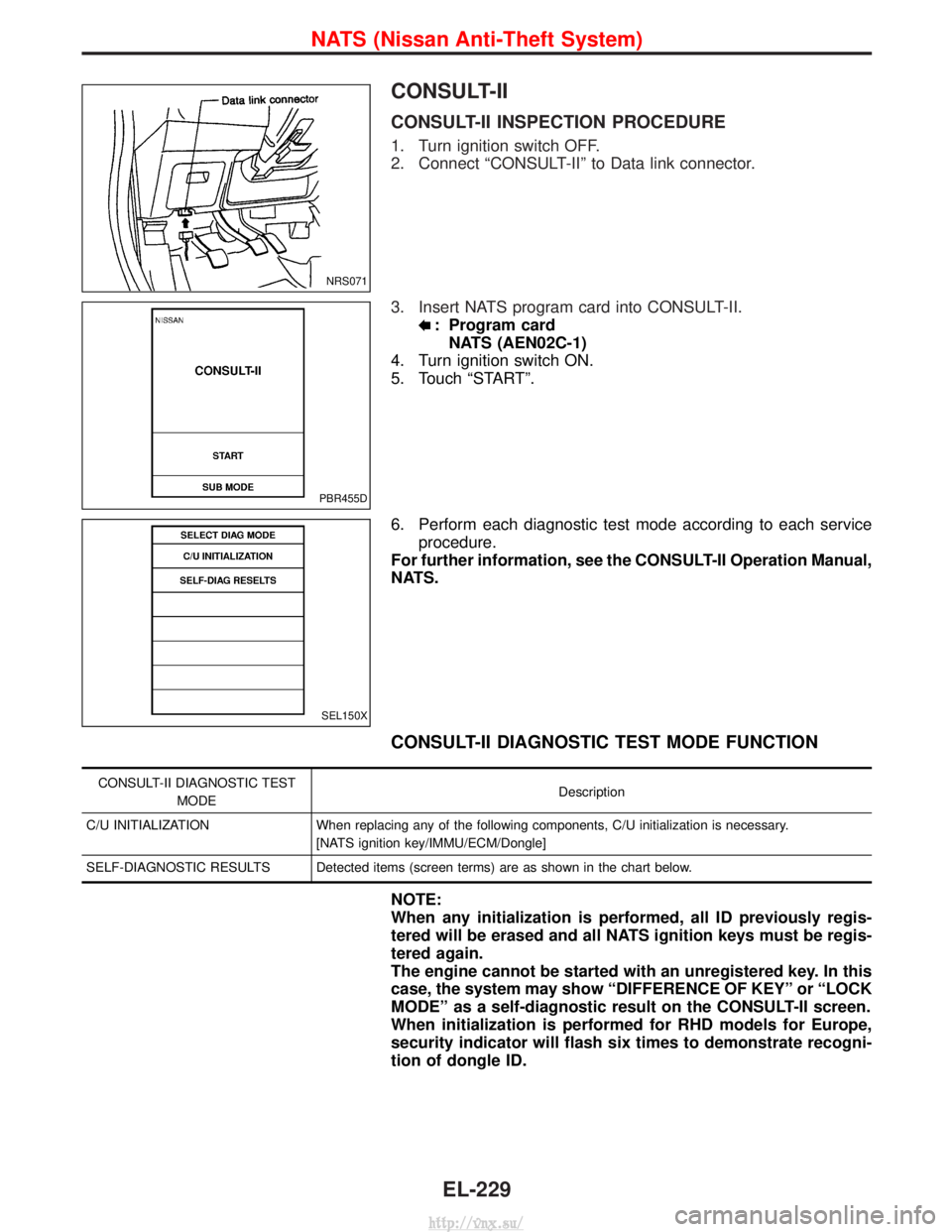
CONSULT-II INSPECTION PROCEDURE
1. Turn ignition switch OFF.
2. Connect ªCONSULT-IIº to Data link connector.
3. Insert NATS program card into CONSULT-II.
: Program cardNATS (AEN02C-1)
4. Turn ignition switch ON.
5. Touch ªSTARTº.
6. Perform each diagnostic test mode according to each service procedure.
For further information, see the CONSULT-II Operation Manual,
NATS.
CONSULT-II DIAGNOSTIC TEST MODE FUNCTION
CONSULT-II DIAGNOSTIC TEST
MODE Description
C/U INITIALIZATION When replacing any of the following components, C/U initialization is necessary. [NATS ignition key/IMMU/ECM/Dongle]
SELF-DIAGNOSTIC RESULTS Detected items (screen terms) are as shown in the chart below.
NOTE:
When any initialization is performed, all ID previously regis-
tered will be erased and all NATS ignition keys must be regis-
tered again.
The engine cannot be started with an unregistered key. In this
case, the system may show ªDIFFERENCE OF KEYº or ªLOCK
MODEº as a self-diagnostic result on the CONSULT-II screen.
When initialization is performed for RHD models for Europe,
security indicator will flash six times to demonstrate recogni-
tion of dongle ID.
NRS071
PBR455D
SEL150X
NATS (Nissan Anti-Theft System)
EL-229
http://vnx.su/