2004 NISSAN TERRANO speedometer
[x] Cancel search: speedometerPage 341 of 1833
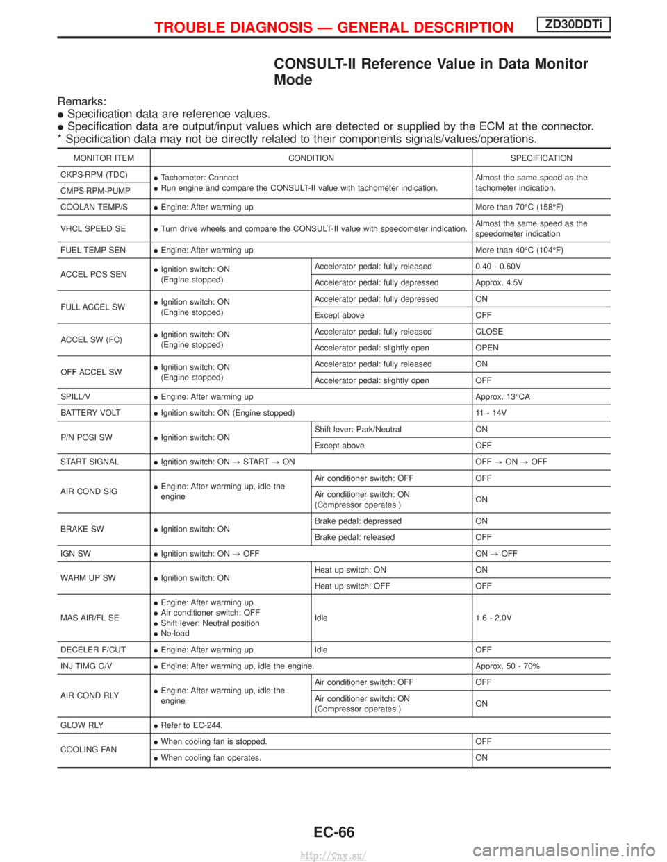
CONSULT-II Reference Value in Data Monitor
Mode
Remarks:
ISpecification data are reference values.
I Specification data are output/input values which are detected or supplied by the ECM at the connector.
* Specification data may not be directly related to their components signals/values/operations.
MONITOR ITEM CONDITION SPECIFICATION
CKPS×RPM (TDC) ITachometer: Connect
I Run engine and compare the CONSULT-II value with tachometer indication. Almost the same speed as the
tachometer indication.
CMPS×RPM-PUMP
COOLAN TEMP/S IEngine: After warming up More than 70ÉC (158ÉF)
VHCL SPEED SE ITurn drive wheels and compare the CONSULT-II value with speedometer indication. Almost the same speed as the
speedometer indication
FUEL TEMP SEN IEngine: After warming up More than 40ÉC (104ÉF)
ACCEL POS SEN I
Ignition switch: ON
(Engine stopped) Accelerator pedal: fully released
0.40 - 0.60V
Accelerator pedal: fully depressed Approx. 4.5V
FULL ACCEL SW I
Ignition switch: ON
(Engine stopped) Accelerator pedal: fully depressed ON
Except above
OFF
ACCEL SW (FC) I
Ignition switch: ON
(Engine stopped) Accelerator pedal: fully released
CLOSE
Accelerator pedal: slightly open OPEN
OFF ACCEL SW I
Ignition switch: ON
(Engine stopped) Accelerator pedal: fully released
ON
Accelerator pedal: slightly open OFF
SPILL/V IEngine: After warming up Approx. 13ÉCA
BATTERY VOLT IIgnition switch: ON (Engine stopped) 11 - 14V
P/N POSI SW IIgnition switch: ON Shift lever: Park/Neutral
ON
Except above OFF
START SIGNAL IIgnition switch: ON ,START ,ON OFF ,ON ,OFF
AIR COND SIG I
Engine: After warming up, idle the
engine Air conditioner switch: OFF OFF
Air conditioner switch: ON
(Compressor operates.)
ON
BRAKE SW IIgnition switch: ON Brake pedal: depressed ON
Brake pedal: released OFF
IGN SW IIgnition switch: ON ,OFF ON ,OFF
WARM UP SW IIgnition switch: ON Heat up switch: ON ON
Heat up switch: OFF OFF
MAS AIR/FL SE I
Engine: After warming up
I Air conditioner switch: OFF
I Shift lever: Neutral position
I No-load Idle 1.6 - 2.0V
DECELER F/CUT IEngine: After warming up Idle OFF
INJ TIMG C/V IEngine: After warming up, idle the engine. Approx. 50 - 70%
AIR COND RLY I
Engine: After warming up, idle the
engine Air conditioner switch: OFF OFF
Air conditioner switch: ON
(Compressor operates.)
ON
GLOW RLY IRefer to EC-244.
COOLING FAN I
When cooling fan is stopped. OFF
I When cooling fan operates. ON
TROUBLE DIAGNOSIS Ð GENERAL DESCRIPTIONZD30DDTi
EC-66
http://vnx.su/
Page 374 of 1833
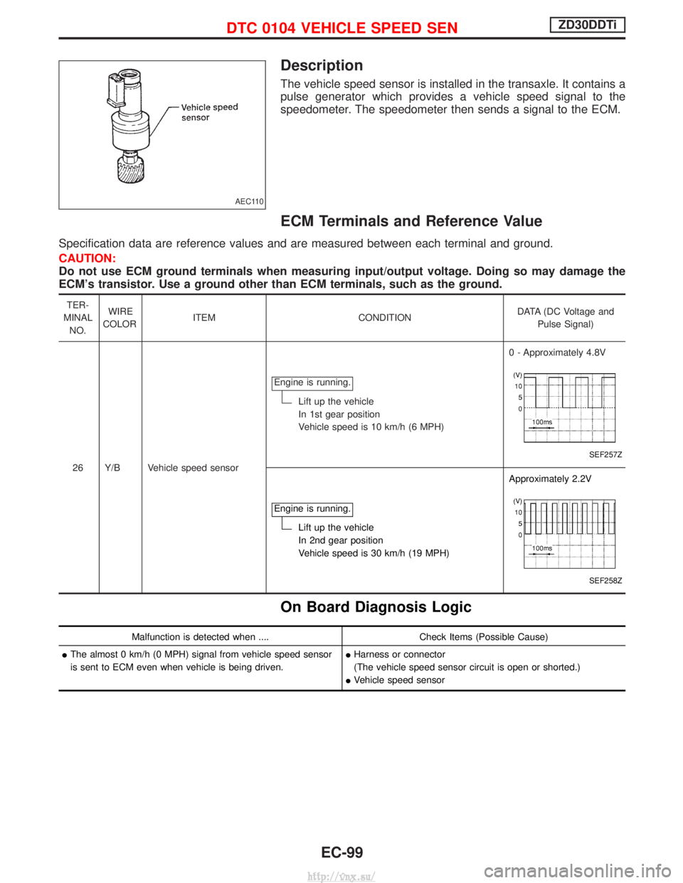
Description
The vehicle speed sensor is installed in the transaxle. It contains a
pulse generator which provides a vehicle speed signal to the
speedometer. The speedometer then sends a signal to the ECM.
ECM Terminals and Reference Value
Specification data are reference values and are measured between each terminal and ground.
CAUTION:
Do not use ECM ground terminals when measuring input/output voltage. Doing so may damage the
ECM's transistor. Use a ground other than ECM terminals, such as the ground.
TER-
MINAL NO. WIRE
COLOR ITEM CONDITION DATA (DC Voltage and
Pulse Signal)
26 Y/B Vehicle speed sensor Engine is running.
Lift up the vehicle
In 1st gear position
Vehicle speed is 10 km/h (6 MPH)
0 - Approximately 4.8V
SEF257Z
Engine is running.
Lift up the vehicle
In 2nd gear position
Vehicle speed is 30 km/h (19 MPH)Approximately 2.2V
SEF258Z
On Board Diagnosis Logic
Malfunction is detected when ....
Check Items (Possible Cause)
I The almost 0 km/h (0 MPH) signal from vehicle speed sensor
is sent to ECM even when vehicle is being driven. I
Harness or connector
(The vehicle speed sensor circuit is open or shorted.)
I Vehicle speed sensor
AEC110
DTC 0104 VEHICLE SPEED SENZD30DDTi
EC-99
http://vnx.su/
Page 378 of 1833

Diagnostic Procedure
1 CHECK VEHICLE SPEED SENSOR INPUT SIGNAL CIRCUIT FOR OPEN AND SHORT
1. Turn ignition switch ªOFFº.
2. Disconnect ECM harness connector and combination meter harness connector.
3. Check harness continuity between ECM terminal 26 and combination meter terminal 26. Refer to Wiring Diagram.Continuity should exist.
4. Also check harness for short to ground and short to power.
OK or NG
OK EGO TO 2.
NG ERepair open circuit or short to ground or short to power in harness or connectors.
2 CHECK SPEEDOMETER FUNCTION
Make sure that speedometer functions properly.
OK or NG
OK EGO TO 4.
NG EGO TO 3.
3 CHECK SPEEDOMETER CIRCUIT FOR OPEN AND SHORT
Check the following.
IHarness connectors F108, E225
I Harness connectors M842, F135 (RHD models)
I Harness for open or short between combination meter and vehicle speed sensor
OK or NG
OK ECheck vehicle speed sensor and combination meter. Refer to EL section.
NG ERepair open circuit or short to ground or short to power in harness or connectors.
4 CHECK INTERMITTENT INCIDENT
Refer to ªTROUBLE DIAGNOSIS FOR INTERMITTENT INCIDENTº, EC-78.
EINSPECTION END
DTC 0104 VEHICLE SPEED SENZD30DDTi
EC-103
http://vnx.su/
Page 641 of 1833
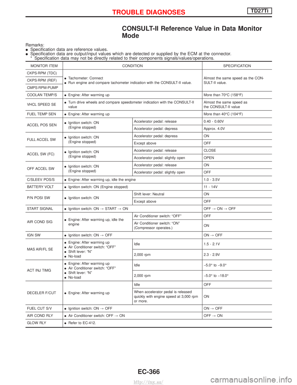
CONSULT-II Reference Value in Data Monitor
Mode
Remarks:
ISpecification data are reference values.
I Specification data are output/input values which are detected or supplied by the ECM at the connector.
* Specification data may not be directly related to their components signals/values/operations.
MONITOR ITEM CONDITION SPECIFICATION
CKPS×RPM (TDC) ITachometer: Connect
I Run engine and compare tachometer indication with the CONSULT-II value. Almost the same speed as the CON-
SULT-II value.
CKPS×RPM (REF)
CMPS×RPM-PUMP
COOLAN TEMP/S
IEngine: After warming up More than 70ÉC (158ÉF)
VHCL SPEED SE I
Turn drive wheels and compare speedometer indication with the CONSULT-II
value Almost the same speed as
the CONSULT-II value
FUEL TEMP SEN IEngine: After warming up More than 40ÉC (104ÉF)
ACCEL POS SEN I
Ignition switch: ON
(Engine stopped) Accelerator pedal: release 0.40 - 0.60V
Accelerator pedal: depress Approx. 4.0V
FULL ACCEL SW I
Ignition switch: ON
(Engine stopped) Accelerator pedal: depress ON
Except above OFF
ACCEL SW (FC) I
Ignition switch: ON
(Engine stopped) Accelerator pedal: release CLOSE
Accelerator pedal: slightly open OPEN
OFF ACCEL SW I
Ignition switch: ON
(Engine stopped) Accelerator pedal: release ON
Accelerator pedal: slightly open OFF
C/SLEEV POS/S IEngine: After warming up, idle the engine 1.0 - 3.5V
BATTERY VOLT IIgnition switch: ON (Engine stopped) 11 - 14V
P/N POSI SW IIgnition switch: ON Shift lever: Neutral ON
Except above OFF
START SIGNAL IIgnition switch: ON ,START ,ON OFF ,ON ,OFF
AIR COND SIG I
Engine: After warming up, idle the
engine Air Conditioner switch: ªOFFº OFF
Air Conditioner switch: ªONº
(Compressor operates.)
ON
IGN SW IIgnition switch: ON ,OFF ON ,OFF
MAS AIR/FL SE I
Engine: After warming up
I Air Conditioner switch: ªOFFº
I Shift lever: ªNº
I No-load Idle 1.5 - 2.1V
2,000 rpm 2.3 - 2.9V
ACT INJ TIMG I
Engine: After warming up
I Air Conditioner switch: ªOFFº
I Shift lever: ªNº
I No-load Idle þ5.0É to þ9.0É
2,000 rpm þ5.0É to þ18.0É
DECELER F/CUT IEngine: After warming up Idle OFF
When accelerator pedal is released
quickly with engine speed at 3,000 rpm
or more.
ON
FUEL CUT S/V IIgnition switch: ON ,OFF ON ,OFF
AIR COND RLY IAir Conditioner switch: OFF ,ON OFF ,ON
GLOW RLY IRefer to EC-412.
TROUBLE DIAGNOSESTD27Ti
EC-366
http://vnx.su/
Page 695 of 1833
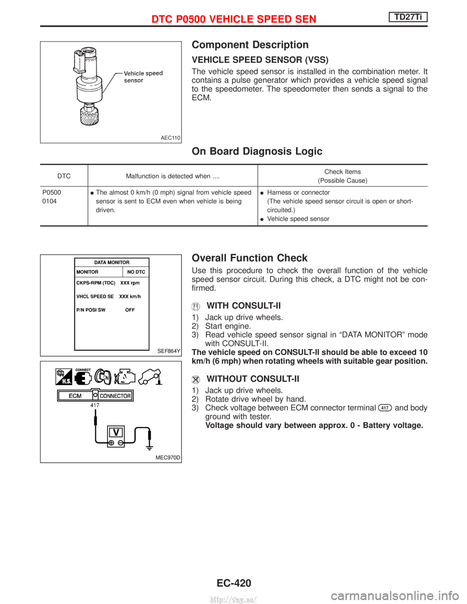
Component Description
VEHICLE SPEED SENSOR (VSS)
The vehicle speed sensor is installed in the combination meter. It
contains a pulse generator which provides a vehicle speed signal
to the speedometer. The speedometer then sends a signal to the
ECM.
On Board Diagnosis Logic
DTCMalfunction is detected when .... Check Items
(Possible Cause)
P0500
0104 I
The almost 0 km/h (0 mph) signal from vehicle speed
sensor is sent to ECM even when vehicle is being
driven. I
Harness or connector
(The vehicle speed sensor circuit is open or short-
circuited.)
I Vehicle speed sensor
Overall Function Check
Use this procedure to check the overall function of the vehicle
speed sensor circuit. During this check, a DTC might not be con-
firmed.
WITH CONSULT-II
1) Jack up drive wheels.
2) Start engine.
3) Read vehicle speed sensor signal in ªDATA MONITORº mode
with CONSULT-II.
The vehicle speed on CONSULT-II should be able to exceed 10
km/h (6 mph) when rotating wheels with suitable gear position.
WITHOUT CONSULT-II
1) Jack up drive wheels.
2) Rotate drive wheel by hand.
3) Check voltage between ECM connector terminal
417and body
ground with tester.
Voltage should vary between approx. 0 - Battery voltage.
AEC110
SEF864Y
MEC970D
DTC P0500 VEHICLE SPEED SENTD27Ti
EC-420
http://vnx.su/
Page 697 of 1833

Diagnostic Procedure
INSPECTION START
CHECK INPUT SIGNAL CIRCUIT.
1. Turn ignition switch to ªLOCKº position.
2. Disconnect ECM harness connector and combination meter harness con-
nector.
3. Check harness continuity between ECM connector terminal
417and
combination meter connector terminal
q
26. Refer to wiring diagram.
Continuity should exist.
If OK, check harness for short-circuit.
OK
ENG Check the following:
IHarness for open or
short-circuit between
ECM and combination
meter
If NG, repair harness or
connectors.
CHECK SPEEDOMETER FUNCTION.
Make sure that speedometer functions
properly.
OK
ENG Check the following:
IHarness for open or
short-circuit between
combination meter and
vehicle speed sensor
If NG, repair harness or
connectors.
Check vehicle speed sen-
sor and its circuit.
Refer to EL section.
Disconnect and reconnect harness con-
nectors in the circuit. Then retest.
Trouble is not fixed.
Check ECM pin terminals for damage and
check the connection of ECM harness
connector. Reconnect ECM harness con-
nector and retest.
INSPECTION END
H
H
H
H
H
DTC P0500 VEHICLE SPEED SENTD27Ti
EC-422
http://vnx.su/
Page 869 of 1833
Vehicle Speed Sensor×MTR
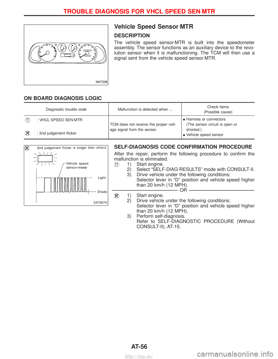
DESCRIPTION
The vehicle speed sensor×MTR is built into the speedometer
assembly. The sensor functions as an auxiliary device to the revo-
lution sensor when it is malfunctioning. The TCM will then use a
signal sent from the vehicle speed sensor×MTR.
ON BOARD DIAGNOSIS LOGIC
Diagnostic trouble codeMalfunction is detected when ... Check items
(Possible cause)
: VHCL SPEED SEN×MTR TCM does not receive the proper volt-
age signal from the sensor.I
Harness or connectors
(The sensor circuit is open or
shorted.)
I Vehicle speed sensor
: 2nd judgement flicker
SELF-DIAGNOSIS CODE CONFIRMATION PROCEDURE
After the repair, perform the following procedure to confirm the
malfunction is eliminated.
1) Start engine.
2) Select ªSELF-DIAG RESULTSº mode with CONSULT-II.
3) Drive vehicle under the following conditions:
Selector lever in ªDº position and vehicle speed higher
than 20 km/h (12 MPH).
----------------------------------------------------------------------------------------------------------------------------------------------------------------------------------------------------------------------------------------------------------- -OR------------------------------------------------------------------------------------------------------------------------------------------------------------------------------------------------------------------------------------------------------------
1) Start engine.
2) Drive vehicle under the following conditions:
Selector lever in ªDº position and vehicle speed higher
than 20 km/h (12 MPH).
3) Perform self-diagnosis. Refer to SELF-DIAGNOSTIC PROCEDURE (Without
CONSULT-II), AT-15.
NAT238
SAT807H
TROUBLE DIAGNOSIS FOR VHCL SPEED SEN ×MTR
AT-56
http://vnx.su/
Page 934 of 1833
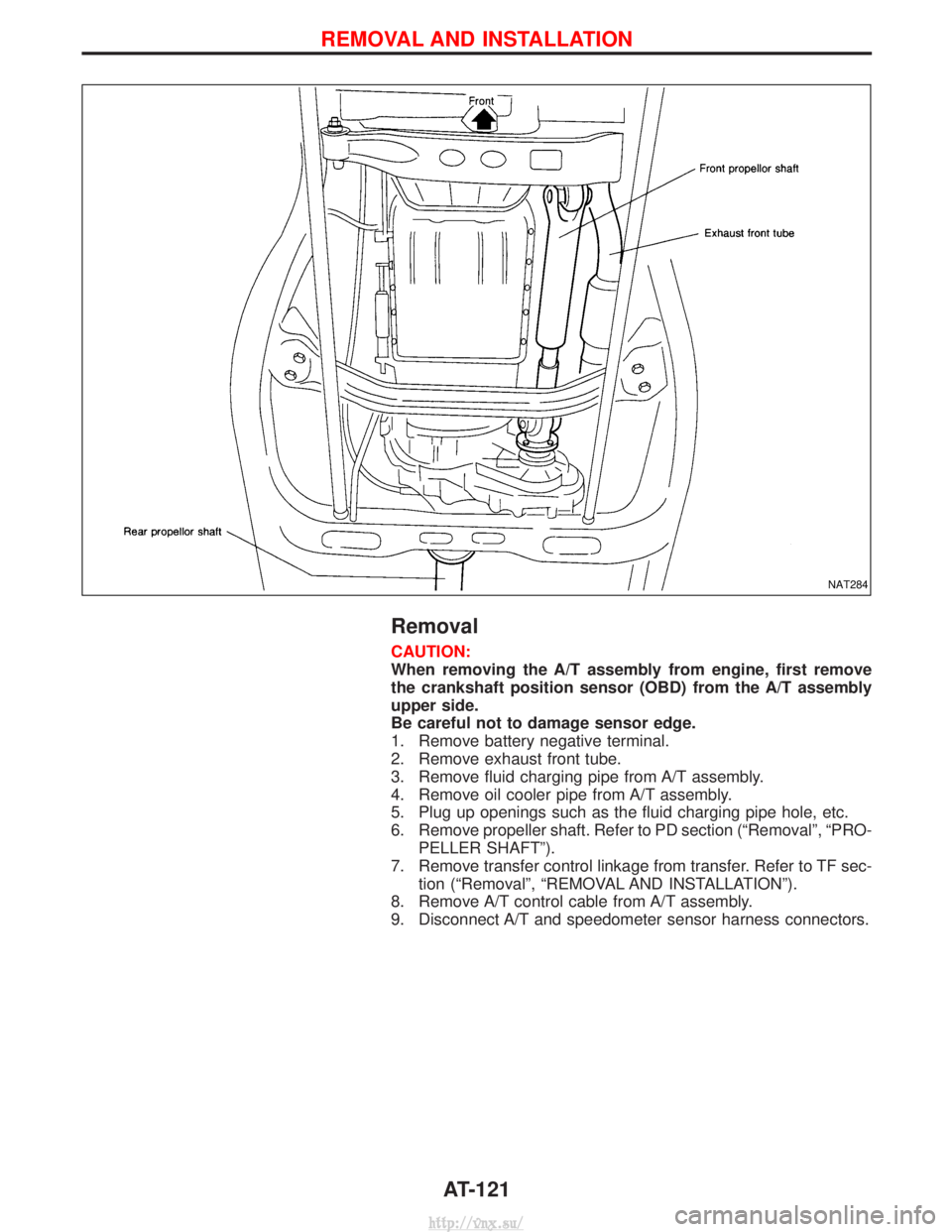
Removal
CAUTION:
When removing the A/T assembly from engine, first remove
the crankshaft position sensor (OBD) from the A/T assembly
upper side.
Be careful not to damage sensor edge.
1. Remove battery negative terminal.
2. Remove exhaust front tube.
3. Remove fluid charging pipe from A/T assembly.
4. Remove oil cooler pipe from A/T assembly.
5. Plug up openings such as the fluid charging pipe hole, etc.
6. Remove propeller shaft. Refer to PD section (ªRemovalº, ªPRO-PELLER SHAFTº).
7. Remove transfer control linkage from transfer. Refer to TF sec- tion (ªRemovalº, ªREMOVAL AND INSTALLATIONº).
8. Remove A/T control cable from A/T assembly.
9. Disconnect A/T and speedometer sensor harness connectors.
NAT284
REMOVAL AND INSTALLATION
AT-121
http://vnx.su/