Page 1034 of 1833
Mainshaft
DISASSEMBLY
1. Check end play of front drive sprocket.Standard:0 - 0.15 mm (0 - 0.0059 in)
If end play is beyond the maximum value, check front drive
sprocket and clutch gear for wear.
2. Remove retaining ring, speedometer drive gear and steel ball.
Be careful not to lose the steel ball.
3. Remove snap ring and spacer.
4. Press out front drive sprocket with mainshaft rear bearing and clutch gear together.
5. Remove needle bearing.
6. Remove bearing retainer and then remove snap ring and spacer.
SMT347A
YMT019
SMT290A
SMT291A
SMT292A
REPAIR FOR COMPONENT PARTS
TF-17
http://vnx.su/
Page 1048 of 1833
k. Install steel ball, speedometer drive gear and retainer ring.
Steel ball is the smallest of check balls for this unit.
l. Install low gear and its bearing to mainshaft.
Apply gear oil to needle bearing.
m. Install L & H hub and snap ring to mainshaft.
Pay special attention to direction of L & H hub.
n. Measure end play of low gear.Standard:0 - 0.15 mm (0 - 0.0059 in)
6. Apply sealant to mating surface and put center case assembly onto front case and tighten bolts.
SMT415A
SMT340A
SMT760A
YMT017
SMT343A
ASSEMBLY
TF-31
http://vnx.su/
Page 1230 of 1833

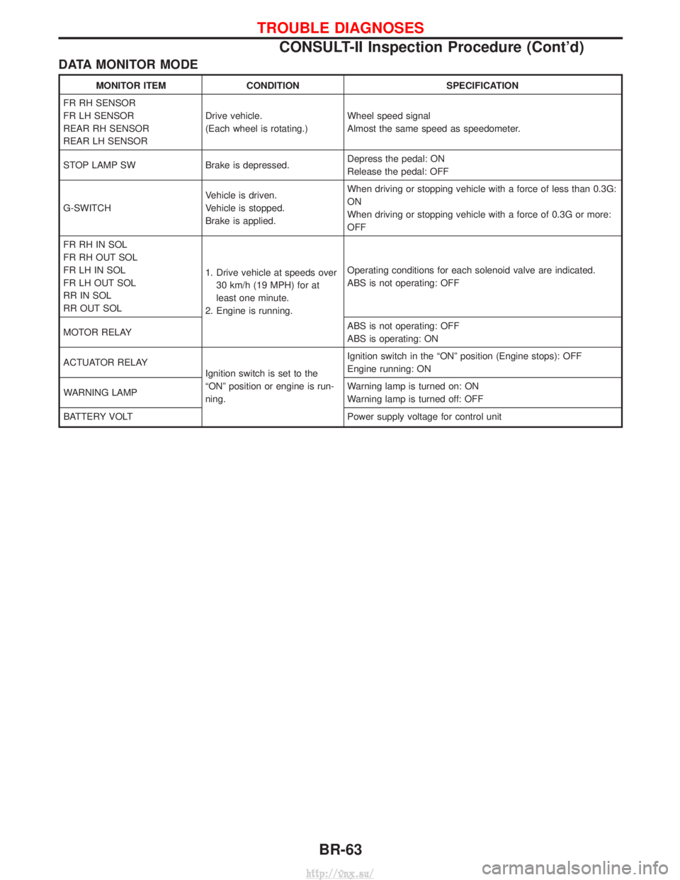
DATA MONITOR MODE
MONITOR ITEMCONDITION SPECIFICATION
FR RH SENSOR
FR LH SENSOR
REAR RH SENSOR
REAR LH SENSOR Drive vehicle.
(Each wheel is rotating.)
Wheel speed signal
Almost the same speed as speedometer.
STOP LAMP SW Brake is depressed. Depress the pedal: ON
Release the pedal: OFF
G-SWITCH Vehicle is driven.
Vehicle is stopped.
Brake is applied.When driving or stopping vehicle with a force of less than 0.3G:
ON
When driving or stopping vehicle with a force of 0.3G or more:
OFF
FR RH IN SOL
FR RH OUT SOL
FR LH IN SOL
FR LH OUT SOL
RR IN SOL
RR OUT SOL 1. Drive vehicle at speeds over
30 km/h (19 MPH) for at
least one minute.
2. Engine is running. Operating conditions for each solenoid valve are indicated.
ABS is not operating: OFF
MOTOR RELAY ABS is not operating: OFF
ABS is operating: ON
ACTUATOR RELAY Ignition switch is set to the
ªONº position or engine is run-
ning.Ignition switch in the ªONº position (Engine stops): OFF
Engine running: ON
WARNING LAMP Warning lamp is turned on: ON
Warning lamp is turned off: OFF
BATTERY VOLT Power supply voltage for control unit
TROUBLE DIAGNOSES
CONSULT-II Inspection Procedure (Cont'd)
BR-63
http://vnx.su/
Page 1575 of 1833
System Description
UNIFIED CONTROL METER
ISpeedometer, odo/trip meter, tachometer, fuel gauge and water temperature gauge are controlled totally
by control unit built-in combination meter.
I Digital meter is adopted for odo/trip meter.*
*The record of the odo meter is kept even if the battery cable is disconnected. The record of the trip meter
is erased when the battery cable is disconnected.
I Odo/trip meter segment can be checked in diagnosis mode.
I Meter/gauge can be checked in diagnosis mode.
HOW TO CHANGE THE DISPLAY FOR ODO/TRIP METER
NOTE:
Turn ignition switch to the ªONº position to operate odo/trip meter.
SEL394X
METER AND GAUGES
EL-82
http://vnx.su/
Page 1576 of 1833
![NISSAN TERRANO 2004 Service Repair Manual POWER SUPPLY AND GROUND CIRCUIT
Power is supplied at all times
Ithrough 10A fuse [No. 16, located in the fuse block (J/B)]
I to combination meter terminal 27.
With the ignition switch in the ON or STA NISSAN TERRANO 2004 Service Repair Manual POWER SUPPLY AND GROUND CIRCUIT
Power is supplied at all times
Ithrough 10A fuse [No. 16, located in the fuse block (J/B)]
I to combination meter terminal 27.
With the ignition switch in the ON or STA](/manual-img/5/57394/w960_57394-1575.png)
POWER SUPPLY AND GROUND CIRCUIT
Power is supplied at all times
Ithrough 10A fuse [No. 16, located in the fuse block (J/B)]
I to combination meter terminal 27.
With the ignition switch in the ON or START position, power is supplied
I through 10A fuse [No. 12, located in the fuse block (J/B)]
I to combination meter terminal 28.
Ground is supplied
I through body grounds F36, F47 (LHD models) or M33, M754 (RHD models)
I to combination meter terminal 29.
WATER TEMPERATURE GAUGE
The water temperature gauge indicates the engine coolant temperature.
Thermal transmitter provides a engine coolant temperature signal to combination meter for water temperature
gauge.
TACHOMETER
The tachometer indicates engine speed in revolution per minutes (rpm). ECM provides an engine speed sig-
nal to combination meter for tachometer.
FUEL GAUGE
The fuel gauge indicates the approximate fuel level in the fuel tank.
The fuel gauge is regulated by a variable ground signal supplied
Ifrom body grounds B10 and B18
I through terminal 3 of the fuel level sensor unit and
I through terminal 2 (TD27Ti engine) or 1 (ZD30DDTi engine) of the fuel level sensor unit
I to combination meter terminal 13 for the fuel gauge.
SPEEDOMETER
The combination meter receives a signal from vehicle speed sensor. The speedometer converts the signal into
the vehicle speed displayed.
AMBIENT TEMPERATURE GAUGE
Ambient temperature sensor provides the signal for ambient temperature to combination meter.
METER AND GAUGES
System Description (Cont'd)
EL-83
http://vnx.su/
Page 1583 of 1833

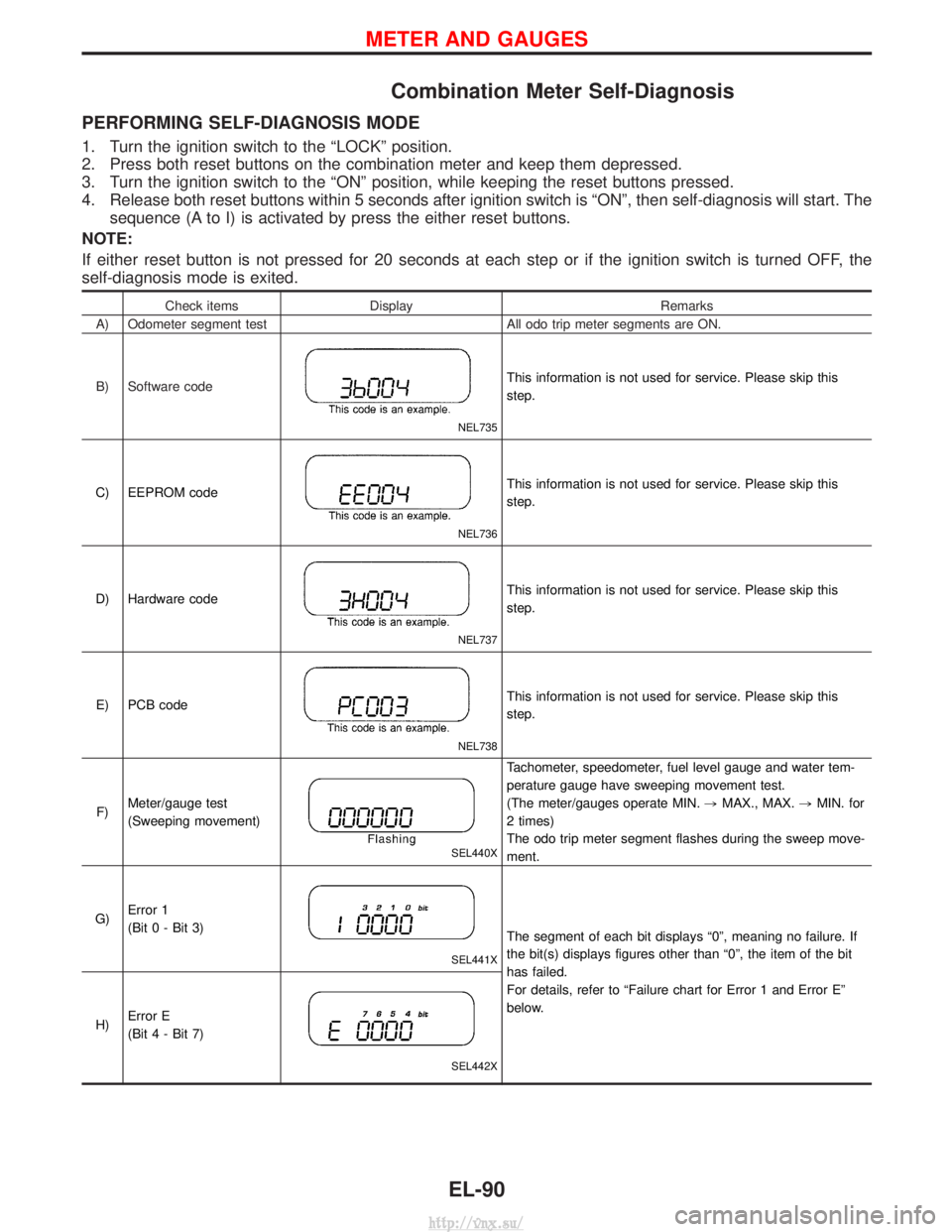
Combination Meter Self-Diagnosis
PERFORMING SELF-DIAGNOSIS MODE
1. Turn the ignition switch to the ªLOCKº position.
2. Press both reset buttons on the combination meter and keep them depressed.
3. Turn the ignition switch to the ªONº position, while keeping the reset buttons pressed.
4. Release both reset buttons within 5 seconds after ignition switch is ªONº, then self-diagnosis will start. Thesequence (A to I) is activated by press the either reset buttons.
NOTE:
If either reset button is not pressed for 20 seconds at each step or if the ignition switch is turned OFF, the
self-diagnosis mode is exited.
Check items Display Remarks
A) Odometer segment test All odo trip meter segments are ON.
B) Software code
NEL735
This information is not used for service. Please skip this
step.
C) EEPROM code
NEL736
This information is not used for service. Please skip this
step.
D) Hardware code
NEL737
This information is not used for service. Please skip this
step.
E) PCB code
NEL738
This information is not used for service. Please skip this
step.
F) Meter/gauge test
(Sweeping movement)
SEL440X
Tachometer, speedometer, fuel level gauge and water tem-
perature gauge have sweeping movement test.
(The meter/gauges operate MIN.
,MAX., MAX. ,MIN. for
2 times)
The odo trip meter segment flashes during the sweep move-
ment.
G) Error 1
(Bit 0 - Bit 3)
SEL441X
The segment of each bit displays ª0º, meaning no failure. If
the bit(s) displays figures other than ª0º, the item of the bit
has failed.
For details, refer to ªFailure chart for Error 1 and Error Eº
below.
H) Error E
(Bit 4 - Bit 7)
SEL442X
METER AND GAUGES
EL-90
http://vnx.su/
Page 1584 of 1833

Check itemsDisplay Remarks
I) Fuel warning lamp test
SEL443X
Fuel warning lamp is on and odo trip meter segment ªFUELº
flashes.
Failure Chart for ªError 1º and ªError Eº
Bit Detectable items Description of the failureDisplayed figure on the
bit
Failure No failure
0 Speedometer input
signal
No input signal
When no signal is detected for 30 minutes continuously with
the ignition ON, it should be judged as signal failure.
(If input signal is detected later, then the judgement will be
canceled immediately.) 1
0
Abnormal input signal
When any signal of frequency which would not exist in normal
conditions is detected, it should be judged as signal failure. 2
1 Tachometer input
signal
No input signal
When no signal is detected for 30 minutes continuously with
the ignition ON, it should be judged as signal failure.
(If input signal is detected later, then the judgement will be
canceled immediately.) 1
0
Abnormal input signal
When any signal of frequency which would not exist in normal
conditions is detected, it should be judged as signal failure. 2
2 Fuel level input sig-
nal
Short circuit
When short circuit of the signal line is detected for 5 seconds
or more, it should be judged as short-circuit failure. 1
0
Open circuit
When open circuit of the signal line is detected for 5 seconds
or more, it should be judged as open-circuit failure. 2
3 Water temperature
input signal Short circuit
When short circuit of the signal line is detected for 5 seconds
or more, it should be judged as short-circuit failure. 10
4 Outside air tempera-
ture input signal
Short circuit
When short circuit of the signal line is detected for 5 seconds
or more, it should be judged as short-circuit failure. 1
0
Open circuit
When open circuit of the signal line is detected for 5 seconds
or more, it should be judged as open-circuit failure. 2
5 Reset buttons Short circuit for reset buttons
When the short circuit is continu-
ously detected for 5 minutes or
more, it should be judged as
short-circuit failure. Right side reset button has
failed.
1
0
Left side reset button has
failed. 2
Both reset buttons have
failed. 3
6Ð Ð 00
7 CPU EEPROM failure 1
0
CPU RAM failure 2
METER AND GAUGES
Combination Meter Self-Diagnosis (Cont'd)
EL-91
http://vnx.su/
Page 1586 of 1833

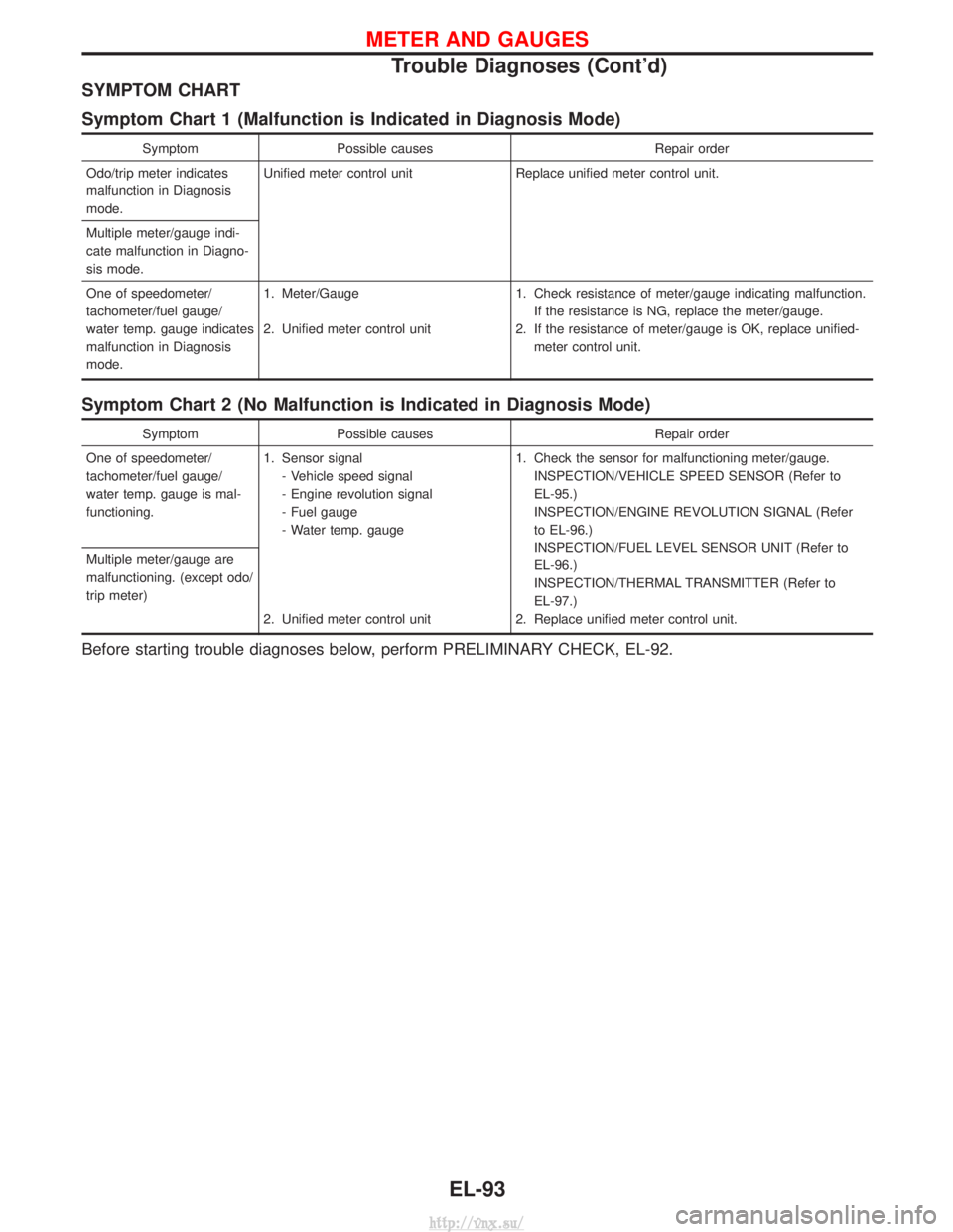
SYMPTOM CHART
Symptom Chart 1 (Malfunction is Indicated in Diagnosis Mode)
SymptomPossible causes Repair order
Odo/trip meter indicates
malfunction in Diagnosis
mode. Unified meter control unit
Replace unified meter control unit.
Multiple meter/gauge indi-
cate malfunction in Diagno-
sis mode.
One of speedometer/
tachometer/fuel gauge/
water temp. gauge indicates
malfunction in Diagnosis
mode. 1. Meter/Gauge
2. Unified meter control unit
1. Check resistance of meter/gauge indicating malfunction.
If the resistance is NG, replace the meter/gauge.
2. If the resistance of meter/gauge is OK, replace unified- meter control unit.
Symptom Chart 2 (No Malfunction is Indicated in Diagnosis Mode)
Symptom Possible causes Repair order
One of speedometer/
tachometer/fuel gauge/
water temp. gauge is mal-
functioning. 1. Sensor signal
- Vehicle speed signal
- Engine revolution signal
- Fuel gauge
- Water temp. gauge
2. Unified meter control unit 1. Check the sensor for malfunctioning meter/gauge.
INSPECTION/VEHICLE SPEED SENSOR (Refer to
EL-95.)
INSPECTION/ENGINE REVOLUTION SIGNAL (Refer
to EL-96.)
INSPECTION/FUEL LEVEL SENSOR UNIT (Refer to
EL-96.)
INSPECTION/THERMAL TRANSMITTER (Refer to
EL-97.)
2. Replace unified meter control unit.
Multiple meter/gauge are
malfunctioning. (except odo/
trip meter)
Before starting trouble diagnoses below, perform PRELIMINARY CHECK, EL-92.
METER AND GAUGES
Trouble Diagnoses (Cont'd)
EL-93
http://vnx.su/