2004 NISSAN TERRANO service
[x] Cancel search: servicePage 1419 of 1833
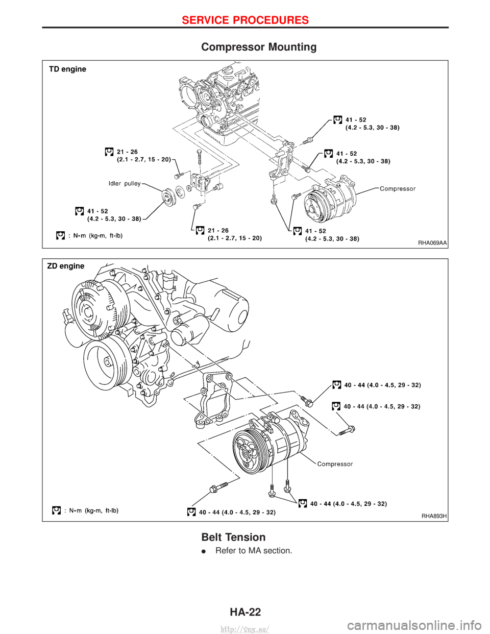
Compressor Mounting
Belt Tension
IRefer to MA section.
RHA069AA
RHA893H
SERVICE PROCEDURES
HA-22
http://vnx.su/
Page 1430 of 1833
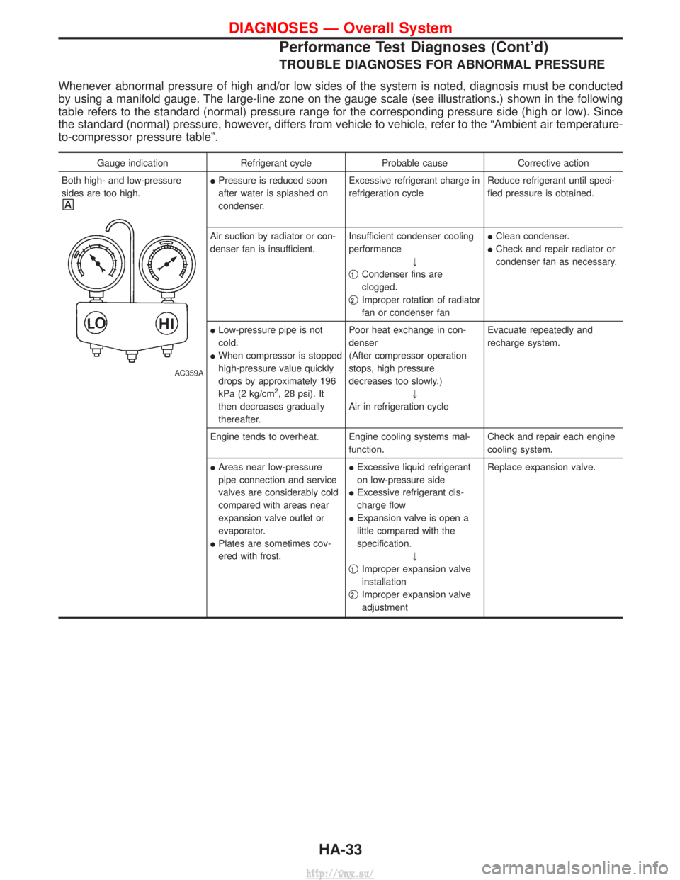
TROUBLE DIAGNOSES FOR ABNORMAL PRESSURE
Whenever abnormal pressure of high and/or low sides of the system is noted, diagnosis must be conducted
by using a manifold gauge. The large-line zone on the gauge scale (see illustrations.) shown in the following
table refers to the standard (normal) pressure range for the corresponding pressure side (high or low). Since
the standard (normal) pressure, however, differs from vehicle to vehicle, refer to the ªAmbient air temperature-
to-compressor pressure tableº.
Gauge indicationRefrigerant cycleProbable causeCorrective action
Both high- and low-pressure
sides are too high.
AC359A
I Pressure is reduced soon
after water is splashed on
condenser. Excessive refrigerant charge in
refrigeration cycle
Reduce refrigerant until speci-
fied pressure is obtained.
Air suction by radiator or con-
denser fan is insufficient. Insufficient condenser cooling
performance
"
q
1Condenser fins are
clogged.
q
2Improper rotation of radiator
fan or condenser fan I
Clean condenser.
I Check and repair radiator or
condenser fan as necessary.
I Low-pressure pipe is not
cold.
I When compressor is stopped
high-pressure value quickly
drops by approximately 196
kPa (2 kg/cm
2, 28 psi). It
then decreases gradually
thereafter. Poor heat exchange in con-
denser
(After compressor operation
stops, high pressure
decreases too slowly.)
"
Air in refrigeration cycle Evacuate repeatedly and
recharge system.
Engine tends to overheat. Engine cooling systems mal- function.Check and repair each engine
cooling system.
I Areas near low-pressure
pipe connection and service
valves are considerably cold
compared with areas near
expansion valve outlet or
evaporator.
I Plates are sometimes cov-
ered with frost. I
Excessive liquid refrigerant
on low-pressure side
I Excessive refrigerant dis-
charge flow
I Expansion valve is open a
little compared with the
specification.
"
q
1Improper expansion valve
installation
q
2Improper expansion valve
adjustment Replace expansion valve.
DIAGNOSES Ð Overall System
Performance Test Diagnoses (Cont'd)
HA-33
http://vnx.su/
Page 1432 of 1833
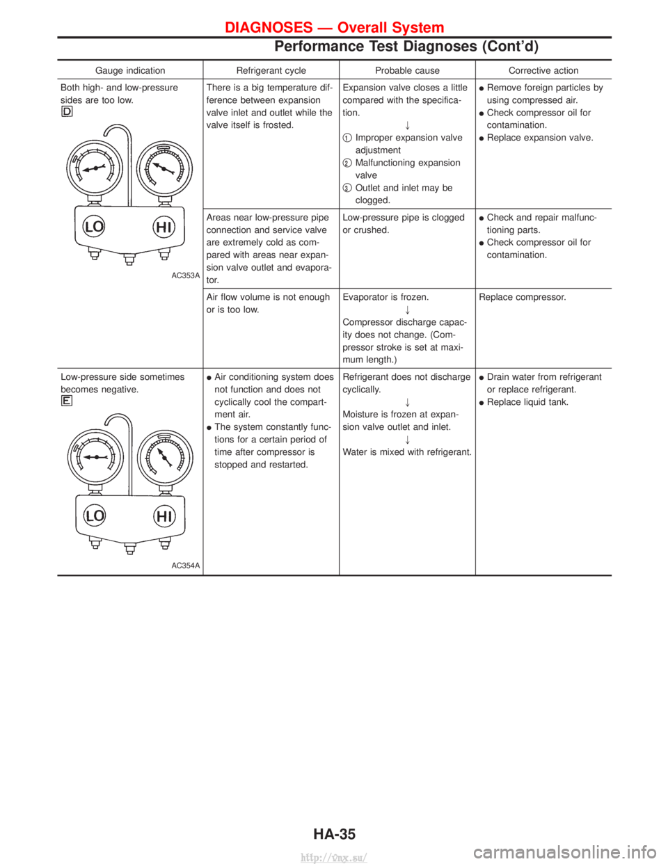
Gauge indicationRefrigerant cycleProbable causeCorrective action
Both high- and low-pressure
sides are too low.
AC353A
There is a big temperature dif-
ference between expansion
valve inlet and outlet while the
valve itself is frosted. Expansion valve closes a little
compared with the specifica-
tion.
"
q
1Improper expansion valve
adjustment
q
2Malfunctioning expansion
valve
q
3Outlet and inlet may be
clogged. I
Remove foreign particles by
using compressed air.
I Check compressor oil for
contamination.
I Replace expansion valve.
Areas near low-pressure pipe
connection and service valve
are extremely cold as com-
pared with areas near expan-
sion valve outlet and evapora-
tor. Low-pressure pipe is clogged
or crushed.
I
Check and repair malfunc-
tioning parts.
I Check compressor oil for
contamination.
Air flow volume is not enough
or is too low. Evaporator is frozen.
"
Compressor discharge capac-
ity does not change. (Com-
pressor stroke is set at maxi-
mum length.) Replace compressor.
Low-pressure side sometimes
becomes negative.
AC354A
I Air conditioning system does
not function and does not
cyclically cool the compart-
ment air.
I The system constantly func-
tions for a certain period of
time after compressor is
stopped and restarted. Refrigerant does not discharge
cyclically.
"
Moisture is frozen at expan-
sion valve outlet and inlet. "
Water is mixed with refrigerant. I
Drain water from refrigerant
or replace refrigerant.
I Replace liquid tank.
DIAGNOSES Ð Overall System
Performance Test Diagnoses (Cont'd)
HA-35
http://vnx.su/
Page 1462 of 1833
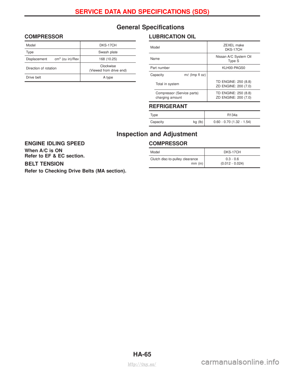
General Specifications
COMPRESSOR
ModelDKS-17CH
Type Swash plate
Displacement cm
3(cu in)/Rev 168 (10.25)
Direction of rotation Clockwise
(Viewed from drive end)
Drive belt A type
LUBRICATION OIL
ModelZEXEL make
DKS-17CH
Name Nissan A/C System Oil
Type S
Part number KLH00-PAGS0
Capacity m (Imp fl oz)
Total in system TD ENGINE: 250 (8.8)
ZD ENGINE: 200 (7.0)
Compressor (Service parts)
charging amount TD ENGINE: 250 (8.8)
ZD ENGINE: 200 (7.0)
REFRIGERANT
Type
R134a
Capacity kg (lb) 0.60 - 0.70 (1.32 - 1.54)
Inspection and Adjustment
ENGINE IDLING SPEED
When A/C is ON
Refer to EF & EC section.
BELT TENSION
Refer to Checking Drive Belts (MA section).
COMPRESSOR
Model DKS-17CH
Clutch disc-to-pulley clearance mm (in)0.3 - 0.6
(0.012 - 0.024)
SERVICE DATA AND SPECIFICATIONS (SDS)
HA-65
http://vnx.su/
Page 1464 of 1833
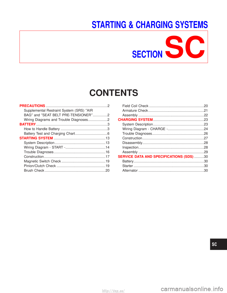
STARTING & CHARGING SYSTEMSSECTION
SC
CONTENTS
PRECAUTIONS ...............................................................2
Supplemental Restraint System (SRS) ²AIR
BAG² and²SEAT BELT PRE-TENSIONER² ...............2
Wiring Diagrams and Trouble Diagnoses....................2
BATTERY ........................................................................\
.3
How to Handle Battery ................................................3
Battery Test and Charging Chart .................................6
STARTING SYSTEM .....................................................13
System Description ....................................................13
Wiring Diagram - START -.........................................14
Trouble Diagnoses.....................................................16
Construction ...............................................................17
Magnetic Switch Check .............................................19
Pinion/Clutch Check ..................................................19
Brush Check ..............................................................20 Field Coil Check ........................................................20
Armature Check .........................................................21
Assembly ...................................................................22
CHARGING SYSTEM ....................................................23
System Description ....................................................23
Wiring Diagram - CHARGE -.....................................24
Trouble Diagnoses.....................................................26
Construction ...............................................................27
Disassembly...............................................................28
Inspection...................................................................28
Assembly ...................................................................29
SERVICE DATA AND SPECIFICATIONS (SDS) ..........30
Battery........................................................................\
30
Starter ........................................................................\
30
Alternator ...................................................................30
http://vnx.su/
Page 1465 of 1833
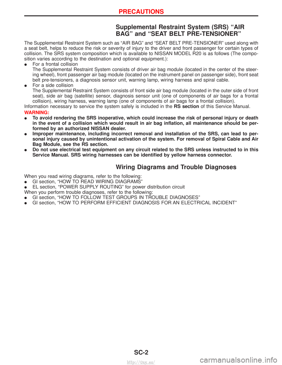
Supplemental Restraint System (SRS) ªAIR
BAGº and ªSEAT BELT PRE-TENSIONERº
The Supplemental Restraint System such as ªAIR BAGº and ªSEAT BELT PRE-TENSIONERº used along with
a seat belt, helps to reduce the risk or severity of injury to the driver and front passenger for certain types of
collision. The SRS system composition which is available to NISSAN MODEL R20 is as follows (The compo-
sition varies according to the destination and optional equipment.):
IFor a frontal collision
The Supplemental Restraint System consists of driver air bag module (located in the center of the steer-
ing wheel), front passenger air bag module (located on the instrument panel on passenger side), front seat
belt pre-tensioners, a diagnosis sensor unit, warning lamp, wiring harness and spiral cable.
I For a side collision
The Supplemental Restraint System consists of front side air bag module (located in the outer side of front
seat), side air bag (satellite) sensor, diagnosis sensor unit (one of components of air bags for a frontal
collision), wiring harness, warning lamp (one of components of air bags for a frontal collision).
Information necessary to service the system safely is included in the RS sectionof this Service Manual.
WARNING:
I To avoid rendering the SRS inoperative, which could increase the risk of personal injury or death
in the event of a collision which would result in air bag inflation, all maintenance should be per-
formed by an authorized NISSAN dealer.
I Improper maintenance, including incorrect removal and installation of the SRS, can lead to per-
sonal injury caused by unintentional activation of the system. For removal of Spiral Cable and Air
Bag Module, see the RS section.
I Do not use electrical test equipment on any circuit related to the SRS unless instructed to in this
Service Manual. SRS wiring harnesses can be identified by yellow harness connector.
Wiring Diagrams and Trouble Diagnoses
When you read wiring diagrams, refer to the following:
IGI section, ªHOW TO READ WIRING DIAGRAMSº
I EL section, ªPOWER SUPPLY ROUTINGº for power distribution circuit
When you perform trouble diagnoses, refer to the following:
I GI section, ªHOW TO FOLLOW TEST GROUPS IN TROUBLE DIAGNOSESº
I GI section, ªHOW TO PERFORM EFFICIENT DIAGNOSIS FOR AN ELECTRICAL INCIDENTº
PRECAUTIONS
SC-2
http://vnx.su/
Page 1493 of 1833
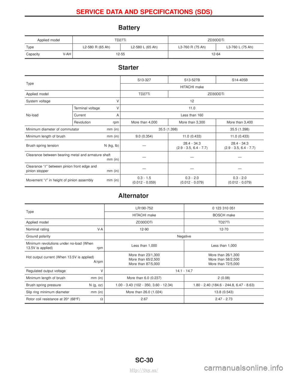
Battery
Applied modelTD27Ti ZD30DDTi
Type L2-580 R (65 Ah)L2-580 L (65 Ah)L3-760 R (75 Ah) L3-760 L (75 Ah)
Capacity V-AH 12-55 12-64
Starter
Type S13-327 S13-527B S14-405B
HITACHI make
Applied model TD27Ti ZD30DDTi
System voltage V 12
No-load Terminal voltage V 11.0
Current A Less than 160
Revolution rpm More than 4,000 More than 3,300 More than 3,400
Minimum diameter of commutator mm (in) 35.5 (1.398) 35.5 (1.398)
Minimum length of brush mm (in) 9.0 (0.354) 11.0 (0.433) 11.0 (0.433)
Brush spring tension N (kg, lb) Ð 28.4 - 34.3
(2.9 - 3.5, 6.4 - 7.7) 28.4 - 34.3
(2.9 - 3.5, 6.4 - 7.7)
Clearance between bearing metal and armature shaft mm (in)ÐÐÐ
Clearance ªº between pinion front edge and
pinion stopper mm (in) ÐÐÐ
Movement ªº in height of pinion assembly mm (in) 0.3 - 1.5
(0.012 - 0.059) 0.3 - 2.0
(0.012 - 0.079) 0.3 - 2.0
(0.012 - 0.079)
Alternator
Type LR190-752 0 123 310 051
HITACHI make BOSCH make
Applied model ZD30DDTi TD27Ti
Nominal rating V-A 12-90 12-70
Ground polarity Negative
Minimum revolutions under no-load (When
13.5V is applied) rpm Less than 1,000 Less than 1,000
Hot output current (When 13.5V is applied) A/rpmMore than 23/1,300
More than 65/2,500
More than 87/5,000 More than 26/1,300
More than 58/2,500
More than 72/5,000
Regulated output voltage V 14.1 - 14.7
Minimum length of brush mm (in) More than 6.0 (0.237) 2 (0.08)
Brush spring pressure N (g, oz) 1.00 - 3.43 (102 - 350, 3.60 - 12.34) 1.80 - 2.40 (184.6 - 244.8, 6.47 - 8.63)
Slip ring minimum diameter mm (in) More than 26.0 (1.024) 13.8 (0.543)
Rotor coil resistance at 20É (68ÉF) W2.67 2.47 - 2.73
SERVICE DATA AND SPECIFICATIONS (SDS)
SC-30
http://vnx.su/
Page 1497 of 1833
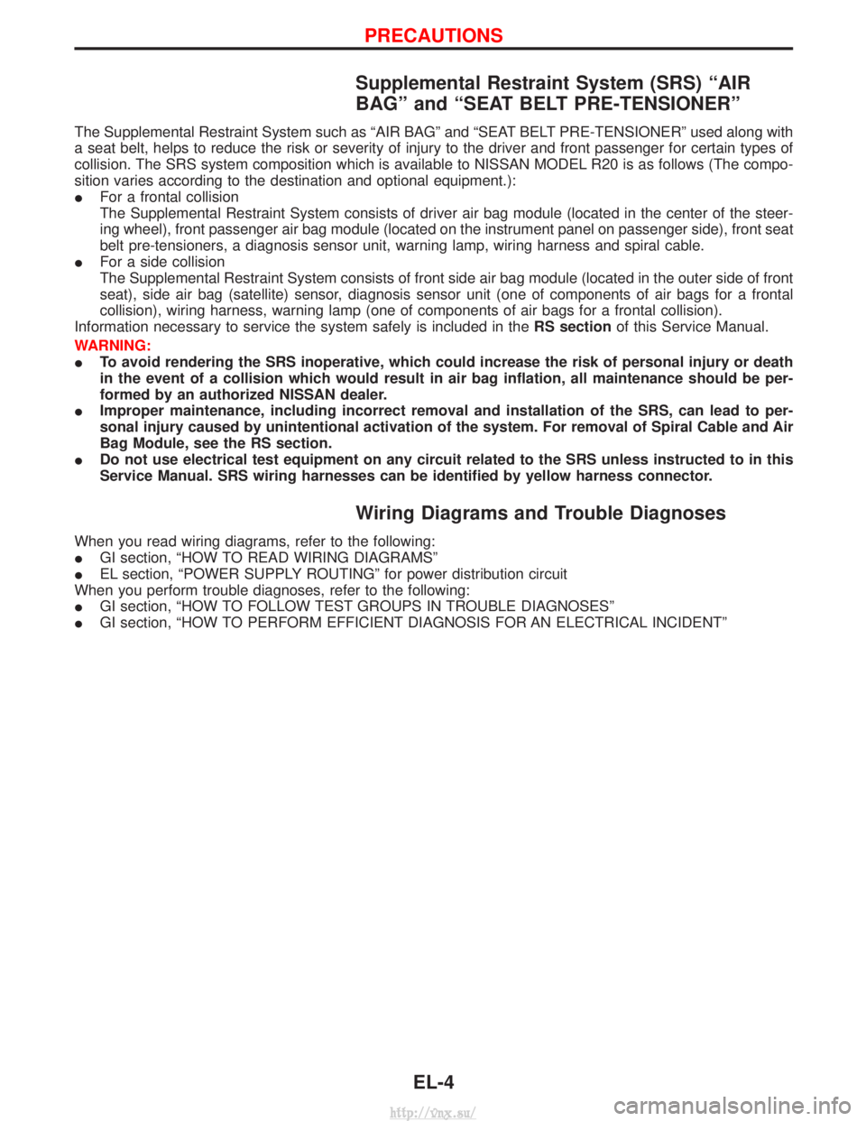
Supplemental Restraint System (SRS) ªAIR
BAGº and ªSEAT BELT PRE-TENSIONERº
The Supplemental Restraint System such as ªAIR BAGº and ªSEAT BELT PRE-TENSIONERº used along with
a seat belt, helps to reduce the risk or severity of injury to the driver and front passenger for certain types of
collision. The SRS system composition which is available to NISSAN MODEL R20 is as follows (The compo-
sition varies according to the destination and optional equipment.):
IFor a frontal collision
The Supplemental Restraint System consists of driver air bag module (located in the center of the steer-
ing wheel), front passenger air bag module (located on the instrument panel on passenger side), front seat
belt pre-tensioners, a diagnosis sensor unit, warning lamp, wiring harness and spiral cable.
I For a side collision
The Supplemental Restraint System consists of front side air bag module (located in the outer side of front
seat), side air bag (satellite) sensor, diagnosis sensor unit (one of components of air bags for a frontal
collision), wiring harness, warning lamp (one of components of air bags for a frontal collision).
Information necessary to service the system safely is included in the RS sectionof this Service Manual.
WARNING:
I To avoid rendering the SRS inoperative, which could increase the risk of personal injury or death
in the event of a collision which would result in air bag inflation, all maintenance should be per-
formed by an authorized NISSAN dealer.
I Improper maintenance, including incorrect removal and installation of the SRS, can lead to per-
sonal injury caused by unintentional activation of the system. For removal of Spiral Cable and Air
Bag Module, see the RS section.
I Do not use electrical test equipment on any circuit related to the SRS unless instructed to in this
Service Manual. SRS wiring harnesses can be identified by yellow harness connector.
Wiring Diagrams and Trouble Diagnoses
When you read wiring diagrams, refer to the following:
IGI section, ªHOW TO READ WIRING DIAGRAMSº
I EL section, ªPOWER SUPPLY ROUTINGº for power distribution circuit
When you perform trouble diagnoses, refer to the following:
I GI section, ªHOW TO FOLLOW TEST GROUPS IN TROUBLE DIAGNOSESº
I GI section, ªHOW TO PERFORM EFFICIENT DIAGNOSIS FOR AN ELECTRICAL INCIDENTº
PRECAUTIONS
EL-4
http://vnx.su/