Page 777 of 1833

General Specifications
CLUTCH CONTROL SYSTEM
Type of clutch controlHydraulic
CLUTCH MASTER CYLINDER
Inner diametermm (in) 15.87 (5/8)
CLUTCH OPERATING CYLINDER
Inner diameter mm (in)
LHD 17.46 (11/16)
RHD 19.05 (3/4)
CLUTCH DISC
Unit: mm (in)
EngineTD27Ti ZD30DDTi
Model 250 260
Facing size
(Outer dia. x inner dia. x
thickness) 250 x 160 x 3.7
(9.84 x 6.30 x 0.1457)
Thickness of disc assembly
under load 7.0 - 7.4 (0.276 - 0.291)
Under a load of 5,884 N (600 kg, 1,323 lb)
CLUTCH COVER
Engine TD27TiZD30DDTi
Model 250 260
Full load N (kg, lb) 5,884 (600, 1,323) 6,760 (689, 1,520)
Inspection and Adjustment
CLUTCH PEDAL
Unit: mm (in)
Handle LHDRHD
Pedal height* 227 - 237
(8.94 - 9.33) 210 - 220
(8.27 - 8.66)
Pedal stroke 155 - 160 (6.10 - 6.30)
Pedal free play
(Backlash at clevis) 1.0 - 3.0 (0.039 - 0.118)
*: Measured from surface of melt sheet to surface of pedal
pad
CLUTCH DISC
Unit: mm (in)
Engine TD27TiZD30DDTi
Disc model 250 260
Rear limit of facing
surface to rivet head 0.3 (0.012)
Runout limit of facing 1 (0.04)
Distance of runout
check point (from the
hub center) 120 (4.72)
Maximum of spline
backlash of spline (at
outer edge of disc) 1.0 (0.039)
CLUTCH COVER
Unit: mm (in)
Engine
TD27TiZD30DDTi
Cover model 250 260
Diaphragm spring height 36.5 - 38.5 (1.437 - 1.516)
Uneven limit of dia-
phragm spring toe height
ªAº 0.7 (0.028)
SERVICE DATA AND SPECIFICATIONS (SDS)
CL-14
http://vnx.su/
Page 778 of 1833

MANUAL TRANSMISSIONSECTION
MT
CONTENTS
PREPARATION ................................................................2
Special Service Tools ..................................................2
Commercial Service Tools ...........................................4
TRANSMISSION FS5R30A .............................................5
Replacing the Rear Oil Seal ........................................5
FS5R30A
ON-VEHICLE SERVICE ..................................................6
Check of Position Switches .........................................6
REMOVAL AND INSTALLATION ....................................7
Removal .......................................................................7
Installation ....................................................................8
MAJOR OVERHAUL .....................................................10
Case Components .....................................................10
Gear Components ..................................................... 11 Shift Control Components .........................................13
DISASSEMBLY ..............................................................14
Case Components .....................................................14
Shift Control Components .........................................15
Gear Components .....................................................16
INSPECTION..................................................................21 Shift Control Components .........................................21
Gear Components .....................................................21
ASSEMBLY ....................................................................23
Gear Components .....................................................23
Shift Control Components .........................................31
Case Components .....................................................32
SERVICE DATA AND SPECIFICATIONS (SDS) ..........34
General Specifications ...............................................34
Inspection and Adjustment ........................................35
http://vnx.su/
Page 779 of 1833
Special Service Tools
*: Special tool or commercial equivalent
Tool number
Tool nameDescription
ST23540000*
Pin punch
Removing and installing retaining pin
ST30031000*
Puller
Removing 1st & 2nd synchronizer assembly
Removing counter gear rear thrust bearing
Removing main drive bearing
ST33290001*
Puller
Removing rear oil seal
ST33230000*
Drift
a: 51 mm (2.01 in) dia.
b: 28.5 mm (1.122 in) dia.
Removing mainshaft and counter gear
ST22350000*
Drift
a: 34 mm (1.34 in) dia.
b: 28 mm (1.10 in) dia.
Removing counter gear front bearing
(Use with KV38100300)
KV38100300*
Drift
a: 54 mm (2.13 in) dia.
b: 32 mm (1.26 in) dia.
Removing counter gear front bearing
(Use with ST22350000)
Installing counter gear rear bearing
ST30720000*
Drift
a: 77 mm (3.03 in) dia.
b: 55.5 mm (2.185 in) dia.
Removing mainshaft front bearing
Installing mainshaft front bearing
PREPARATION
MT-2
http://vnx.su/
Page 780 of 1833

*: Special tool or commercial equivalent
Tool number
Tool nameDescription
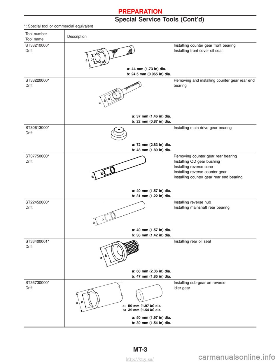
ST33210000*
Drift
a: 44 mm (1.73 in) dia.
b: 24.5 mm (0.965 in) dia.
Installing counter gear front bearing
Installing front cover oil seal
ST33220000*
Drift
a: 37 mm (1.46 in) dia.
b: 22 mm (0.87 in) dia.
Removing and installing counter gear rear end
bearing
ST30613000*
Drift
a: 72 mm (2.83 in) dia.
b: 48 mm (1.89 in) dia.
Installing main drive gear bearing
ST37750000*
Drift
a: 40 mm (1.57 in) dia.
b: 31 mm (1.22 in) dia.
Removing counter gear rear bearing
Installing OD gear bushing
Installing reverse cone
Installing reverse counter gear
Installing counter gear rear end bearing
ST22452000*
Drift
a: 40 mm (1.57 in) dia.
b: 36 mm (1.42 in) dia.
Installing reverse hub
Installing mainshaft rear bearing
ST33400001*
Drift
a: 60 mm (2.36 in) dia.
b: 47 mm (1.85 in) dia.
Installing rear oil seal
ST36730000*
Drift
a: 50 mm (1.97 in) dia.
b: 39 mm (1.54 in) dia.
Installing sub-gear on reverse
idler gear
PREPARATION
Special Service Tools (Cont'd)
MT-3
http://vnx.su/
Page 781 of 1833
Commercial Service Tools
Tool nameDescription
Puller
NT077
Removing counter gear rear end bearing
Removing mainshaft rear bearing
Removing reverse synchronizer hub
Removing reverse counter gear
Drift
ST22452000
a: 44.5 mm (1.752 in) dia.
b: 38.5 mm (1.516 in) dia.
Installing sub-gear snap ring
Drift
ST22452000
a: 44.5 mm (1.752 in) dia.
b: 40.5 mm (1.594 in) dia.
Installing OD main gear
Installing reverse gear bushing
PREPARATION
MT-4
http://vnx.su/
Page 783 of 1833
Check of Position Switches
SwitchGear position Continuity
q
14WD* Transfer case 4WD Yes
Except 4WD No
q
2Back-up lamp Transmission
case Reverse Yes
Except reverse No
*: Ensure both sides of 4WD 2-pole double-throw switch is operational, refer to ªWarning lampsº wiring diagram in EL-Section.
YMT009
ON-VEHICLE SERVICEFS5R30A
MT-6
http://vnx.su/
Page 811 of 1833
General Specifications
EngineTD27Ti and ZD30DDTi
Transmission model FS5R30A
No. of speeds 5
Shift pattern
Synchromesh type Warner
Gear ratio 1st 3.580
2nd 2.077
3rd 1.360
4th 1.000
OD 0.811
Reverse 3.631
No. of teeth Mainshaftdrive
1st 32
2nd 30
3rd 29
4th 22
OD 24
Reverse 30
Countershaft Drive
1st 13
2nd 21
3rd 31
4th 32
OD 43
Reverse 12
Reverse idler gear 22
Oil capacity (lmp pt) 3.6 (6-3/8)
SERVICE DATA AND SPECIFICATIONS (SDS)
MT-34
http://vnx.su/
Page 812 of 1833

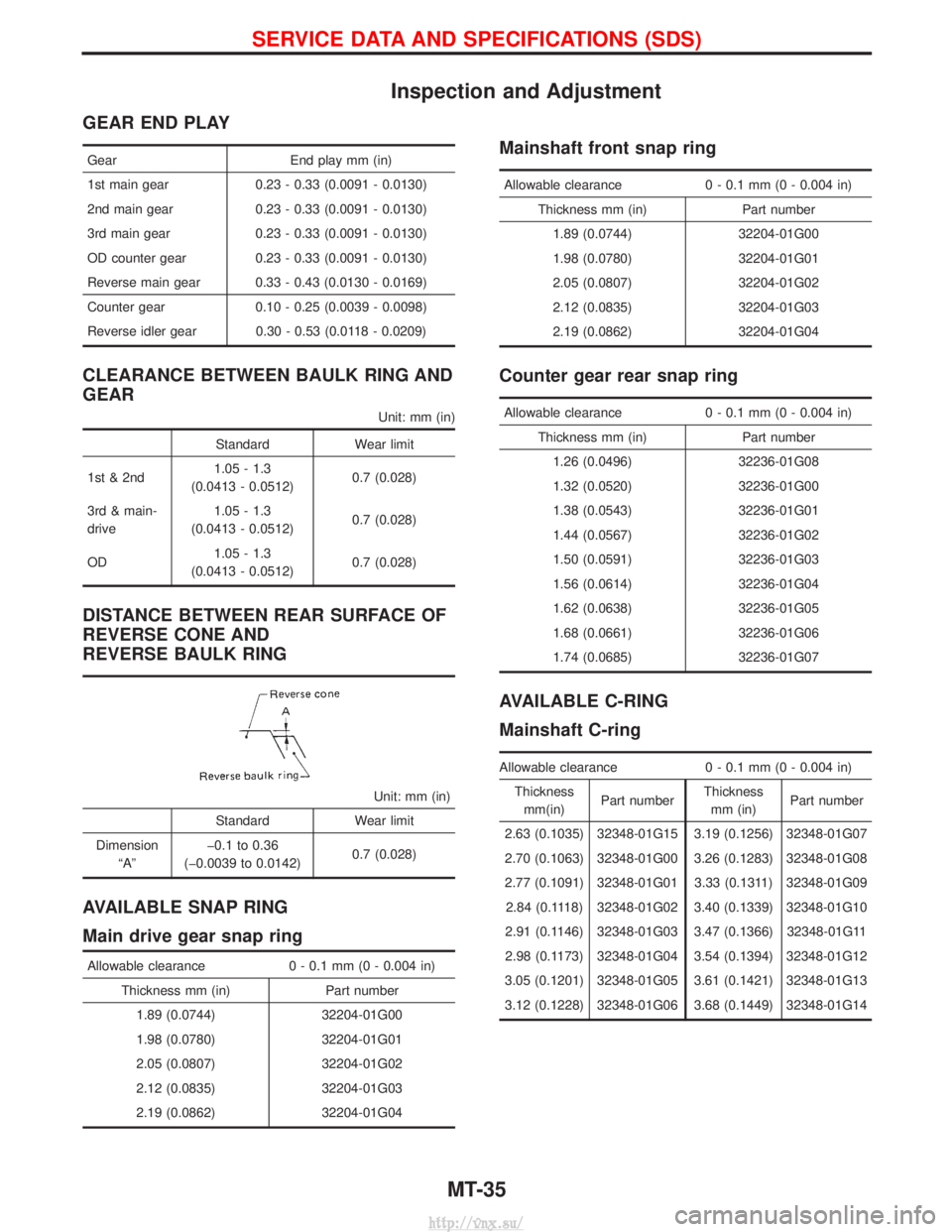
Inspection and Adjustment
GEAR END PLAY
GearEnd play mm (in)
1st main gear 0.23 - 0.33 (0.0091 - 0.0130)
2nd main gear 0.23 - 0.33 (0.0091 - 0.0130)
3rd main gear 0.23 - 0.33 (0.0091 - 0.0130)
OD counter gear 0.23 - 0.33 (0.0091 - 0.0130)
Reverse main gear 0.33 - 0.43 (0.0130 - 0.0169)
Counter gear 0.10 - 0.25 (0.0039 - 0.0098)
Reverse idler gear 0.30 - 0.53 (0.0118 - 0.0209)
CLEARANCE BETWEEN BAULK RING AND
GEAR
Unit: mm (in)
Standard Wear limit
1st & 2nd 1.05 - 1.3
(0.0413 - 0.0512) 0.7 (0.028)
3rd & main-
drive 1.05 - 1.3
(0.0413 - 0.0512) 0.7 (0.028)
OD 1.05 - 1.3
(0.0413 - 0.0512) 0.7 (0.028)
DISTANCE BETWEEN REAR SURFACE OF
REVERSE CONE AND
REVERSE BAULK RING
Unit: mm (in)
Standard Wear limit
Dimension ªAº þ0.1 to 0.36
(þ0.0039 to 0.0142) 0.7 (0.028)
AVAILABLE SNAP RING
Main drive gear snap ring
Allowable clearance
0 - 0.1 mm (0 - 0.004 in)
Thickness mm (in) Part number 1.89 (0.0744) 32204-01G00
1.98 (0.0780) 32204-01G01
2.05 (0.0807) 32204-01G02
2.12 (0.0835) 32204-01G03
2.19 (0.0862) 32204-01G04
Mainshaft front snap ring
Allowable clearance 0 - 0.1 mm (0 - 0.004 in)
Thickness mm (in) Part number 1.89 (0.0744) 32204-01G00
1.98 (0.0780) 32204-01G01
2.05 (0.0807) 32204-01G02
2.12 (0.0835) 32204-01G03
2.19 (0.0862) 32204-01G04
Counter gear rear snap ring
Allowable clearance 0 - 0.1 mm (0 - 0.004 in)
Thickness mm (in) Part number 1.26 (0.0496) 32236-01G08
1.32 (0.0520) 32236-01G00
1.38 (0.0543) 32236-01G01
1.44 (0.0567) 32236-01G02
1.50 (0.0591) 32236-01G03
1.56 (0.0614) 32236-01G04
1.62 (0.0638) 32236-01G05
1.68 (0.0661) 32236-01G06
1.74 (0.0685) 32236-01G07
AVAILABLE C-RING
Mainshaft C-ring
Allowable clearance 0 - 0.1 mm (0 - 0.004 in)
Thickness mm(in) Part number Thickness
mm (in) Part number
2.63 (0.1035) 32348-01G15 3.19 (0.1256) 32348-01G07
2.70 (0.1063) 32348-01G00 3.26 (0.1283) 32348-01G08
2.77 (0.1091) 32348-01G01 3.33 (0.1311) 32348-01G09 2.84 (0.1118) 32348-01G02 3.40 (0.1339) 32348-01G10
2.91 (0.1146) 32348-01G03 3.47 (0.1366) 32348-01G11
2.98 (0.1173) 32348-01G04 3.54 (0.1394) 32348-01G12
3.05 (0.1201) 32348-01G05 3.61 (0.1421) 32348-01G13
3.12 (0.1228) 32348-01G06 3.68 (0.1449) 32348-01G14
SERVICE DATA AND SPECIFICATIONS (SDS)
MT-35
http://vnx.su/