2004 NISSAN TERRANO service
[x] Cancel search: servicePage 305 of 1833
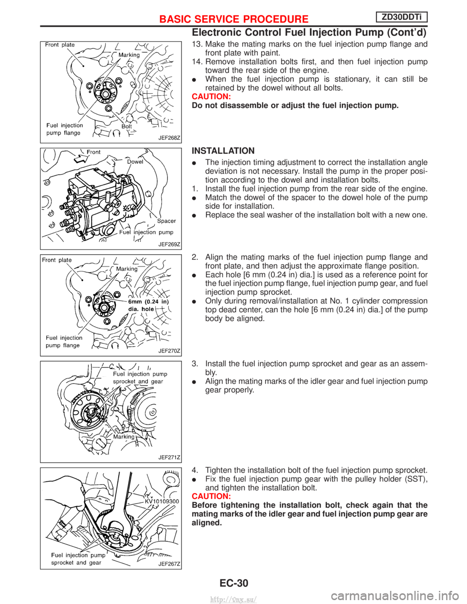
13. Make the mating marks on the fuel injection pump flange andfront plate with paint.
14. Remove installation bolts first, and then fuel injection pump toward the rear side of the engine.
I When the fuel injection pump is stationary, it can still be
retained by the dowel without all bolts.
CAUTION:
Do not disassemble or adjust the fuel injection pump.
INSTALLATION
I The injection timing adjustment to correct the installation angle
deviation is not necessary. Install the pump in the proper posi-
tion according to the dowel and installation bolts.
1. Install the fuel injection pump from the rear side of the engine.
I Match the dowel of the spacer to the dowel hole of the pump
side for installation.
I Replace the seal washer of the installation bolt with a new one.
2. Align the mating marks of the fuel injection pump flange and front plate, and then adjust the approximate flange position.
I Each hole [6 mm (0.24 in) dia.] is used as a reference point for
the fuel injection pump flange, fuel injection pump gear, and fuel
injection pump sprocket.
I Only during removal/installation at No. 1 cylinder compression
top dead center, can the hole [6 mm (0.24 in) dia.] of the pump
body be aligned.
3. Install the fuel injection pump sprocket and gear as an assem- bly.
I Align the mating marks of the idler gear and fuel injection pump
gear properly.
4. Tighten the installation bolt of the fuel injection pump sprocket.
I Fix the fuel injection pump gear with the pulley holder (SST),
and tighten the installation bolt.
CAUTION:
Before tightening the installation bolt, check again that the
mating marks of the idler gear and fuel injection pump gear are
aligned.
JEF268Z
JEF269Z
JEF270Z
JEF271Z
JEF267Z
BASIC SERVICE PROCEDUREZD30DDTi
Electronic Control Fuel Injection Pump (Cont'd)
EC-30
http://vnx.su/
Page 306 of 1833
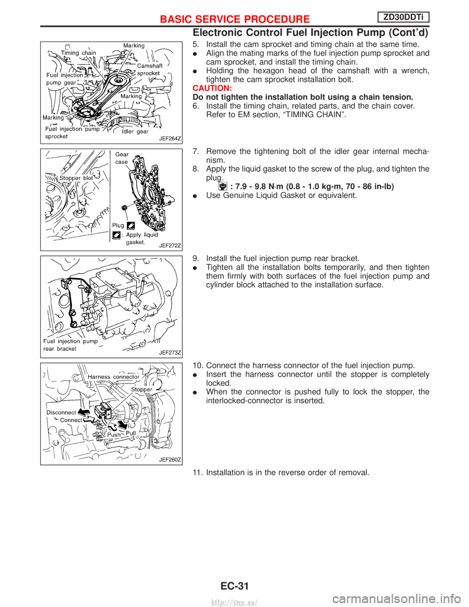
5. Install the cam sprocket and timing chain at the same time.
IAlign the mating marks of the fuel injection pump sprocket and
cam sprocket, and install the timing chain.
I Holding the hexagon head of the camshaft with a wrench,
tighten the cam sprocket installation bolt.
CAUTION:
Do not tighten the installation bolt using a chain tension.
6. Install the timing chain, related parts, and the chain cover. Refer to EM section, ªTIMING CHAINº.
7. Remove the tightening bolt of the idler gear internal mecha- nism.
8. Apply the liquid gasket to the screw of the plug, and tighten the plug.
: 7.9 - 9.8 N ×m (0.8 - 1.0 kg-m, 70 - 86 in-lb)
I Use Genuine Liquid Gasket or equivalent.
9. Install the fuel injection pump rear bracket.
I Tighten all the installation bolts temporarily, and then tighten
them firmly with both surfaces of the fuel injection pump and
cylinder block attached to the installation surface.
10. Connect the harness connector of the fuel injection pump.
I Insert the harness connector until the stopper is completely
locked.
I When the connector is pushed fully to lock the stopper, the
interlocked-connector is inserted.
11. Installation is in the reverse order of removal.
JEF264Z
JEF272Z
JEF273Z
JEF260Z
BASIC SERVICE PROCEDUREZD30DDTi
Electronic Control Fuel Injection Pump (Cont'd)
EC-31
http://vnx.su/
Page 307 of 1833
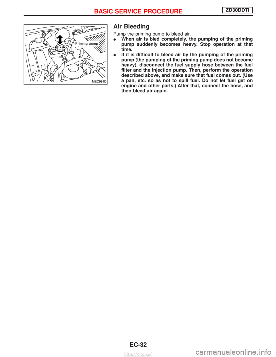
Air Bleeding
Pump the priming pump to bleed air.
IWhen air is bled completely, the pumping of the priming
pump suddenly becomes heavy. Stop operation at that
time.
I If it is difficult to bleed air by the pumping of the priming
pump (the pumping of the priming pump does not become
heavy), disconnect the fuel supply hose between the fuel
filter and the injection pump. Then, perform the operation
described above, and make sure that fuel comes out. (Use
a pan, etc. so as not to spill fuel. Do not let fuel get on
engine and other parts.) After that, connect the hose, and
then bleed air again.
MEC991D
BASIC SERVICE PROCEDUREZD30DDTi
EC-32
http://vnx.su/
Page 314 of 1833
CONSULT-II
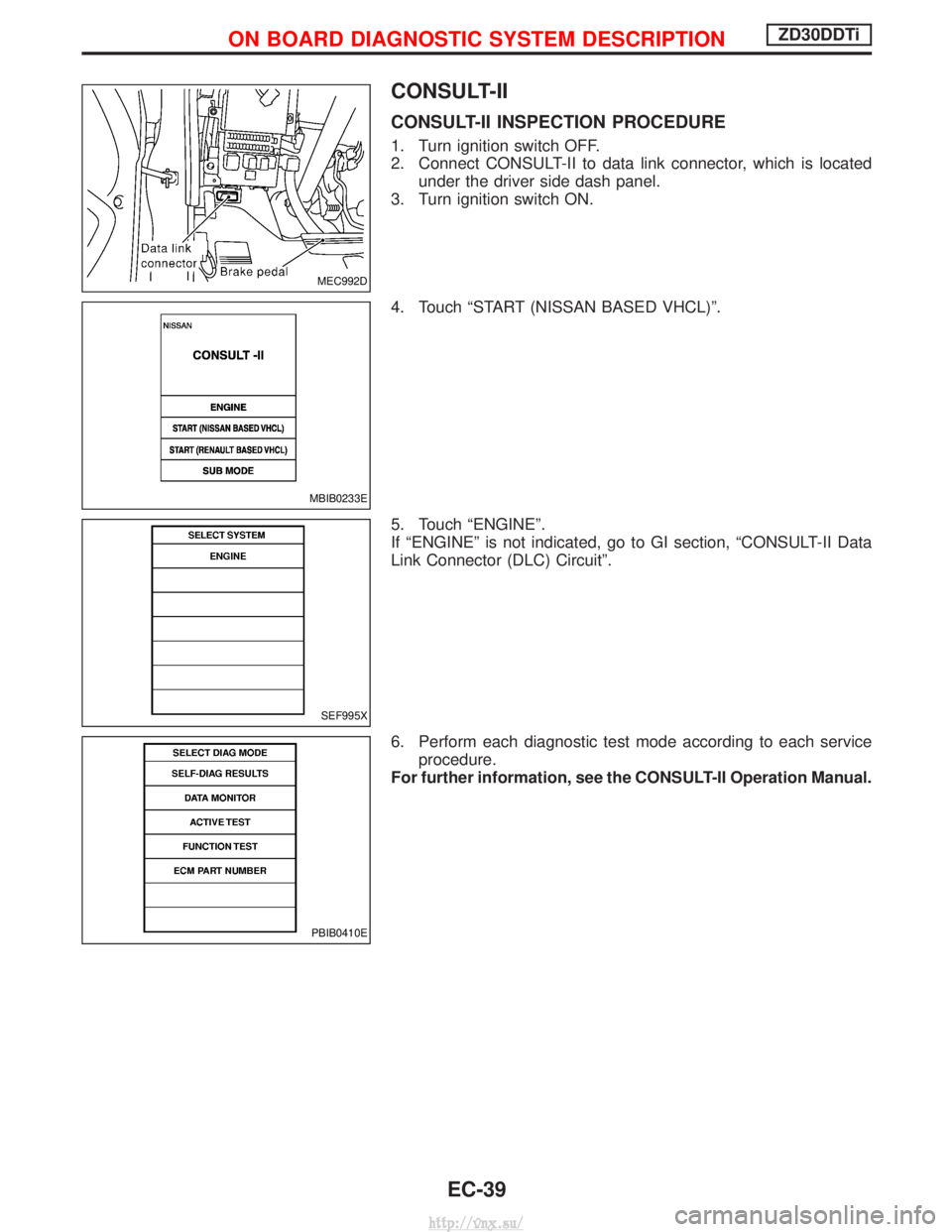
CONSULT-II INSPECTION PROCEDURE
1. Turn ignition switch OFF.
2. Connect CONSULT-II to data link connector, which is locatedunder the driver side dash panel.
3. Turn ignition switch ON.
4. Touch ªSTART (NISSAN BASED VHCL)º.
5. Touch ªENGINEº.
If ªENGINEº is not indicated, go to GI section, ªCONSULT-II Data
Link Connector (DLC) Circuitº.
6. Perform each diagnostic test mode according to each service procedure.
For further information, see the CONSULT-II Operation Manual.
MEC992D
MBIB0233E
SEF995X
PBIB0410E
ON BOARD DIAGNOSTIC SYSTEM DESCRIPTIONZD30DDTi
EC-39
http://vnx.su/
Page 324 of 1833
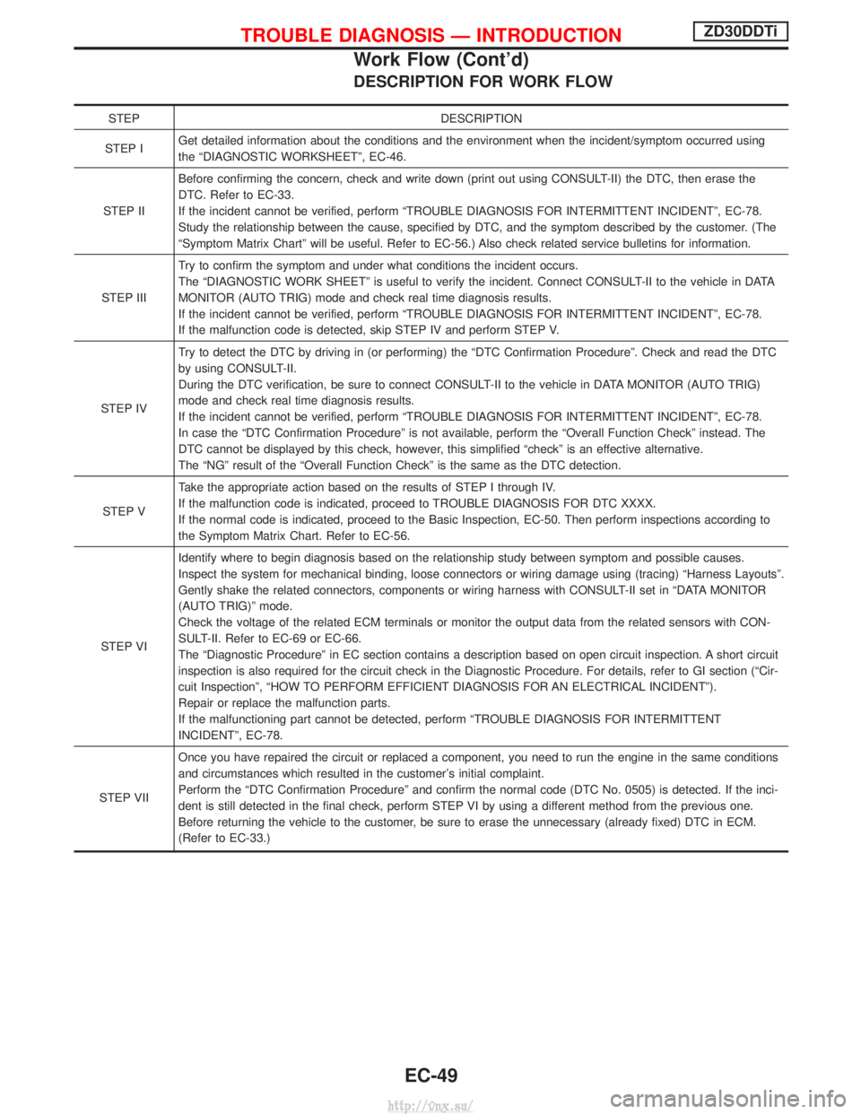
DESCRIPTION FOR WORK FLOW
STEPDESCRIPTION
STEP I Get detailed information about the conditions and the environment when the incident/symptom occurred using
the ªDIAGNOSTIC WORKSHEETº, EC-46.
STEP II Before confirming the concern, check and write down (print out using CONSULT-II) the DTC, then erase the
DTC. Refer to EC-33.
If the incident cannot be verified, perform ªTROUBLE DIAGNOSIS FOR INTERMITTENT INCIDENTº, EC-78.
Study the relationship between the cause, specified by DTC, and the symptom described by the customer. (The
ªSymptom Matrix Chartº will be useful. Refer to EC-56.) Also check related service bulletins for information.
STEP III Try to confirm the symptom and under what conditions the incident occurs.
The ªDIAGNOSTIC WORK SHEETº is useful to verify the incident. Connect CONSULT-II to the vehicle in DATA
MONITOR (AUTO TRIG) mode and check real time diagnosis results.
If the incident cannot be verified, perform ªTROUBLE DIAGNOSIS FOR INTERMITTENT INCIDENTº, EC-78.
If the malfunction code is detected, skip STEP IV and perform STEP V.
STEP IV Try to detect the DTC by driving in (or performing) the ªDTC Confirmation Procedureº. Check and read the DTC
by using CONSULT-II.
During the DTC verification, be sure to connect CONSULT-II to the vehicle in DATA MONITOR (AUTO TRIG)
mode and check real time diagnosis results.
If the incident cannot be verified, perform ªTROUBLE DIAGNOSIS FOR INTERMITTENT INCIDENTº, EC-78.
In case the ªDTC Confirmation Procedureº is not available, perform the ªOverall Function Checkº instead. The
DTC cannot be displayed by this check, however, this simplified ªcheckº is an effective alternative.
The ªNGº result of the ªOverall Function Checkº is the same as the DTC detection.
STEP V Take the appropriate action based on the results of STEP I through IV.
If the malfunction code is indicated, proceed to TROUBLE DIAGNOSIS FOR DTC XXXX.
If the normal code is indicated, proceed to the Basic Inspection, EC-50. Then perform inspections according to
the Symptom Matrix Chart. Refer to EC-56.
STEP VI Identify where to begin diagnosis based on the relationship study between symptom and possible causes.
Inspect the system for mechanical binding, loose connectors or wiring damage using (tracing) ªHarness Layoutsº.
Gently shake the related connectors, components or wiring harness with CONSULT-II set in ªDATA MONITOR
(AUTO TRIG)º mode.
Check the voltage of the related ECM terminals or monitor the output data from the related sensors with CON-
SULT-II. Refer to EC-69 or EC-66.
The ªDiagnostic Procedureº in EC section contains a description based on open circuit inspection. A short circuit
inspection is also required for the circuit check in the Diagnostic Procedure. For details, refer to GI section (ªCir-
cuit Inspectionº, ªHOW TO PERFORM EFFICIENT DIAGNOSIS FOR AN ELECTRICAL INCIDENTº).
Repair or replace the malfunction parts.
If the malfunctioning part cannot be detected, perform ªTROUBLE DIAGNOSIS FOR INTERMITTENT
INCIDENTº, EC-78.
STEP VII Once you have repaired the circuit or replaced a component, you need to run the engine in the same conditions
and circumstances which resulted in the customer's initial complaint.
Perform the ªDTC Confirmation Procedureº and confirm the normal code (DTC No. 0505) is detected. If the inci-
dent is still detected in the final check, perform STEP VI by using a different method from the previous one.
Before returning the vehicle to the customer, be sure to erase the unnecessary (already fixed) DTC in ECM.
(Refer to EC-33.)
TROUBLE DIAGNOSIS Ð INTRODUCTIONZD30DDTi
Work Flow (Cont'd)
EC-49
http://vnx.su/
Page 325 of 1833
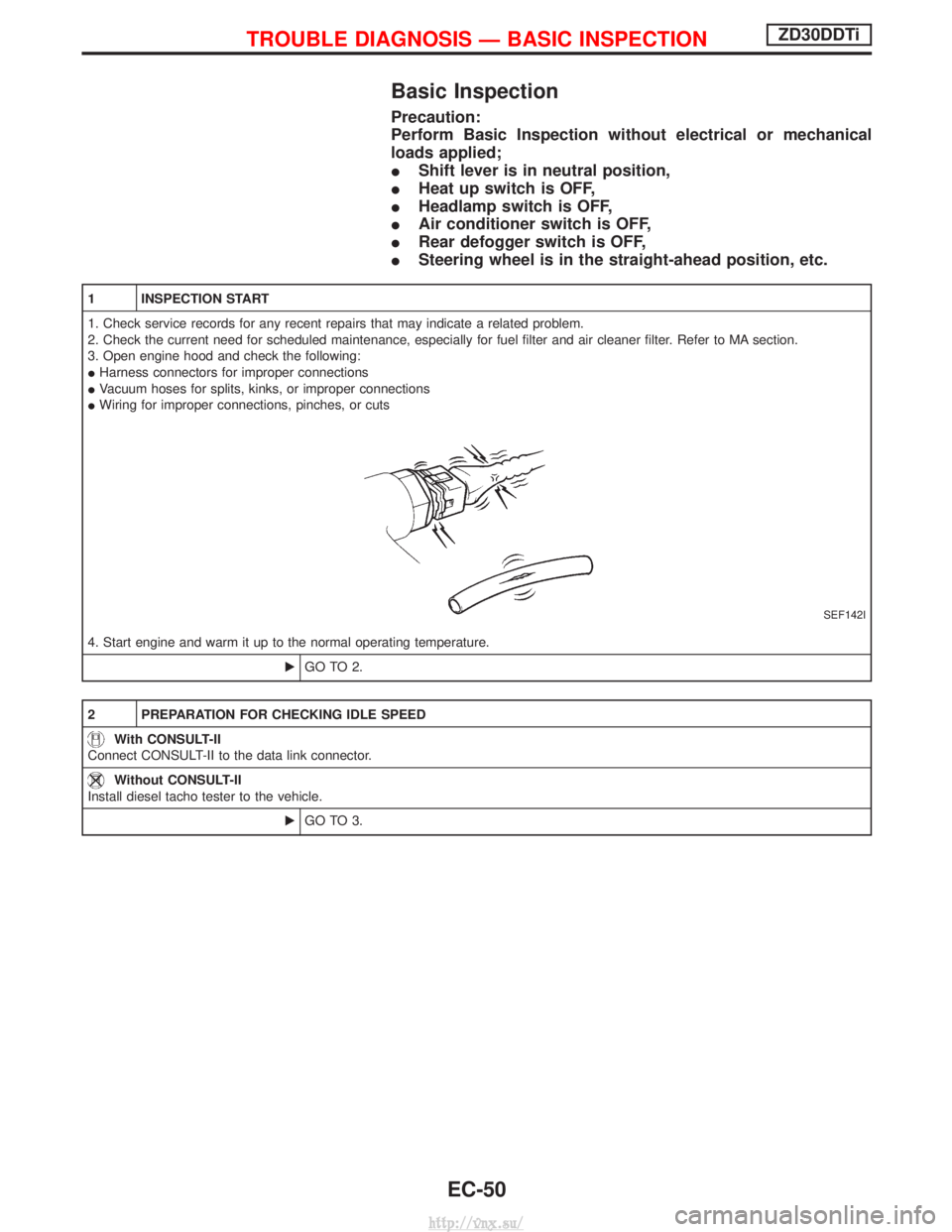
Basic Inspection
Precaution:
Perform Basic Inspection without electrical or mechanical
loads applied;
IShift lever is in neutral position,
I Heat up switch is OFF,
I Headlamp switch is OFF,
I Air conditioner switch is OFF,
I Rear defogger switch is OFF,
I Steering wheel is in the straight-ahead position, etc.
1 INSPECTION START
1. Check service records for any recent repairs that may indicate a related problem.
2. Check the current need for scheduled maintenance, especially for fuel filter and air cleaner filter. Refer to MA section.
3. Open engine hood and check the following:
IHarness connectors for improper connections
I Vacuum hoses for splits, kinks, or improper connections
I Wiring for improper connections, pinches, or cuts
SEF142I
4. Start engine and warm it up to the normal operating temperature.
EGO TO 2.
2 PREPARATION FOR CHECKING IDLE SPEED
With CONSULT-II
Connect CONSULT-II to the data link connector.
Without CONSULT-II
Install diesel tacho tester to the vehicle.
EGO TO 3.
TROUBLE DIAGNOSIS Ð BASIC INSPECTIONZD30DDTi
EC-50
http://vnx.su/
Page 587 of 1833
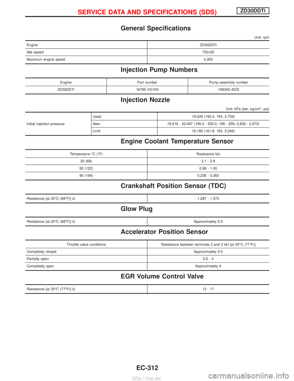
General Specifications
Unit: rpm
EngineZD30DDTi
Idle speed 750 25
Maximum engine speed 4,300
Injection Pump Numbers
EnginePart numberPump assembly number
ZD30DDTi 16700 VG100 109342-4023
Injection Nozzle
Unit: kPa (bar, kg/cm2, psi)
Initial injection pressureUsed 19,026 (190.3, 194, 2,759)
New 19,516 - 20,497 (195.2 - 205.0, 199 - 209, 2,830 - 2,972)
Limit 16,182 (161.8, 165, 2,346)
Engine Coolant Temperature Sensor
Temperature ÉC (ÉF)
Resistance kW
20 (68) 2.1 - 2.9
50 (122) 0.68 - 1.00
90 (194) 0.236 - 0.260
Crankshaft Position Sensor (TDC)
Resistance [at 20ÉC (68ÉF)] W 1,287 - 1,573
Glow Plug
Resistance [at 20ÉC (68ÉF)]W Approximately 0.5
Accelerator Position Sensor
Throttle valve conditionsResistance between terminals 2 and 3 kW[at 25ÉC (77ÉF)]
Completely closed Approximately 0.5
Partially open 0.5-4
Completely open Approximately 4
EGR Volume Control Valve
Resistance [at 25ÉC (77ÉF)]W 13-17
SERVICE DATA AND SPECIFICATIONS (SDS)ZD30DDTi
EC-312
http://vnx.su/
Page 590 of 1833
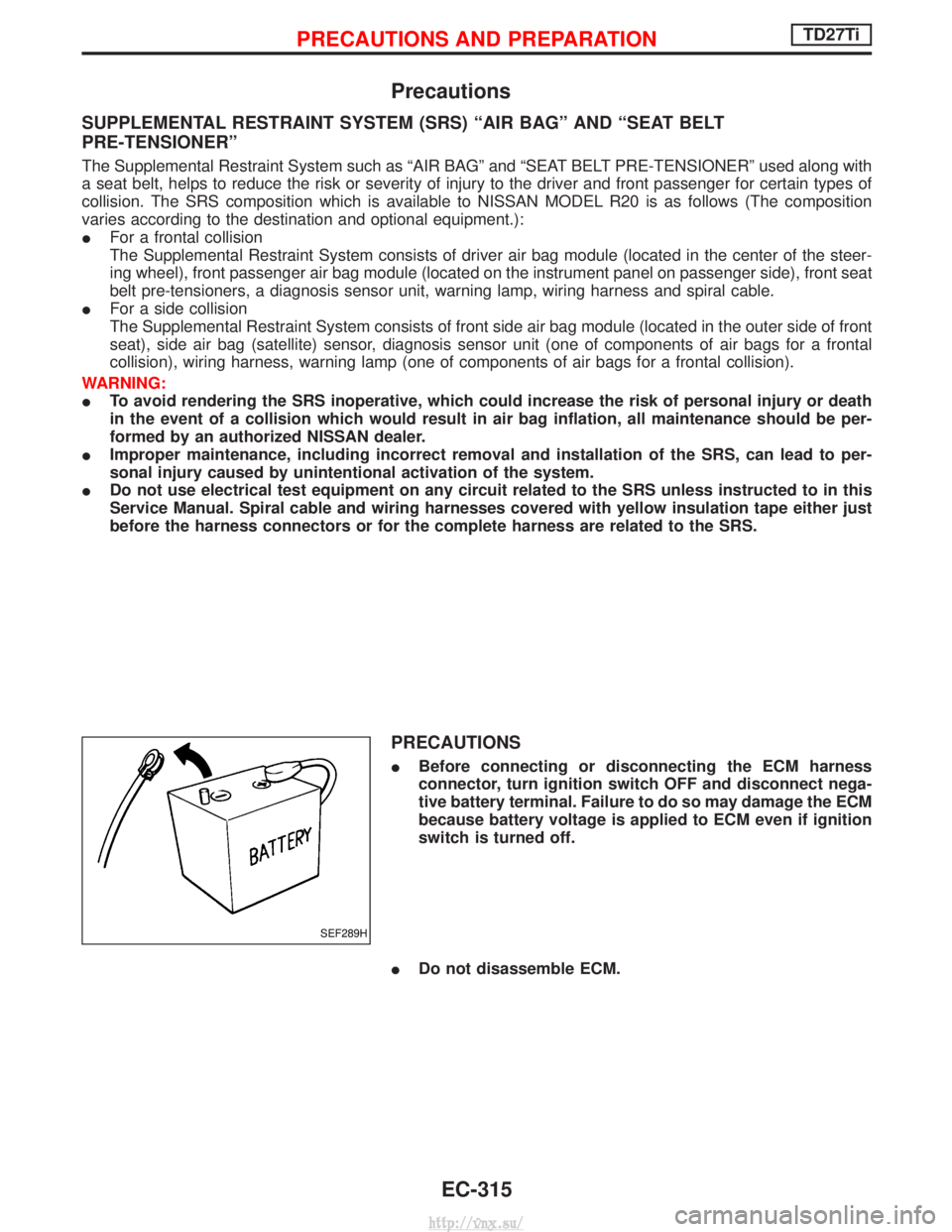
Precautions
SUPPLEMENTAL RESTRAINT SYSTEM (SRS) ªAIR BAGº AND ªSEAT BELT
PRE-TENSIONERº
The Supplemental Restraint System such as ªAIR BAGº and ªSEAT BELT PRE-TENSIONERº used along with
a seat belt, helps to reduce the risk or severity of injury to the driver and front passenger for certain types of
collision. The SRS composition which is available to NISSAN MODEL R20 is as follows (The composition
varies according to the destination and optional equipment.):
IFor a frontal collision
The Supplemental Restraint System consists of driver air bag module (located in the center of the steer-
ing wheel), front passenger air bag module (located on the instrument panel on passenger side), front seat
belt pre-tensioners, a diagnosis sensor unit, warning lamp, wiring harness and spiral cable.
I For a side collision
The Supplemental Restraint System consists of front side air bag module (located in the outer side of front
seat), side air bag (satellite) sensor, diagnosis sensor unit (one of components of air bags for a frontal
collision), wiring harness, warning lamp (one of components of air bags for a frontal collision).
WARNING:
I To avoid rendering the SRS inoperative, which could increase the risk of personal injury or death
in the event of a collision which would result in air bag inflation, all maintenance should be per-
formed by an authorized NISSAN dealer.
I Improper maintenance, including incorrect removal and installation of the SRS, can lead to per-
sonal injury caused by unintentional activation of the system.
I Do not use electrical test equipment on any circuit related to the SRS unless instructed to in this
Service Manual. Spiral cable and wiring harnesses covered with yellow insulation tape either just
before the harness connectors or for the complete harness are related to the SRS.
PRECAUTIONS
IBefore connecting or disconnecting the ECM harness
connector, turn ignition switch OFF and disconnect nega-
tive battery terminal. Failure to do so may damage the ECM
because battery voltage is applied to ECM even if ignition
switch is turned off.
I Do not disassemble ECM.
SEF289H
PRECAUTIONS AND PREPARATIONTD27Ti
EC-315
http://vnx.su/