2004 NISSAN TERRANO service
[x] Cancel search: servicePage 240 of 1833
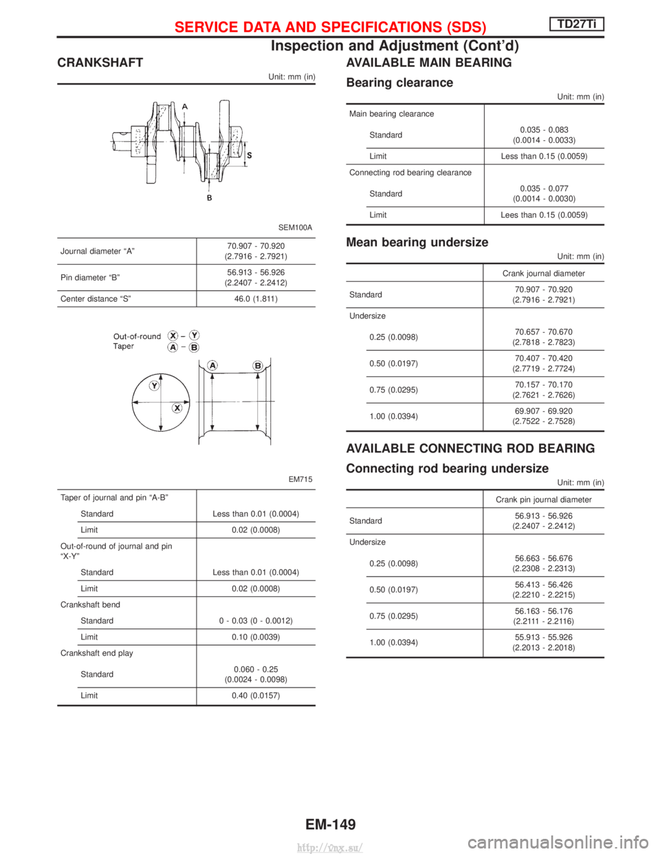
CRANKSHAFT
Unit: mm (in)
SEM100A
Journal diameter ªAº70.907 - 70.920
(2.7916 - 2.7921)
Pin diameter ªBº 56.913 - 56.926
(2.2407 - 2.2412)
Center distance ªSº 46.0 (1.811)
EM715
Taper of journal and pin ªA-Bº Standard Less than 0.01 (0.0004)
Limit 0.02 (0.0008)
Out-of-round of journal and pin
ªX-Yº Standard Less than 0.01 (0.0004)
Limit 0.02 (0.0008)
Crankshaft bend Standard 0 - 0.03 (0 - 0.0012)
Limit 0.10 (0.0039)
Crankshaft end play
Standard 0.060 - 0.25
(0.0024 - 0.0098)
Limit 0.40 (0.0157)
AVAILABLE MAIN BEARING
Bearing clearance
Unit: mm (in)
Main bearing clearance
Standard 0.035 - 0.083
(0.0014 - 0.0033)
Limit Less than 0.15 (0.0059)
Connecting rod bearing clearance
Standard 0.035 - 0.077
(0.0014 - 0.0030)
Limit Lees than 0.15 (0.0059)
Mean bearing undersize
Unit: mm (in)
Crank journal diameter
Standard 70.907 - 70.920
(2.7916 - 2.7921)
Undersize
0.25 (0.0098) 70.657 - 70.670
(2.7818 - 2.7823)
0.50 (0.0197) 70.407 - 70.420
(2.7719 - 2.7724)
0.75 (0.0295) 70.157 - 70.170
(2.7621 - 2.7626)
1.00 (0.0394) 69.907 - 69.920
(2.7522 - 2.7528)
AVAILABLE CONNECTING ROD BEARING
Connecting rod bearing undersize
Unit: mm (in)
Crank pin journal diameter
Standard 56.913 - 56.926
(2.2407 - 2.2412)
Undersize
0.25 (0.0098) 56.663 - 56.676
(2.2308 - 2.2313)
0.50 (0.0197) 56.413 - 56.426
(2.2210 - 2.2215)
0.75 (0.0295) 56.163 - 56.176
(2.2111 - 2.2116)
1.00 (0.0394) 55.913 - 55.926
(2.2013 - 2.2018)
SERVICE DATA AND SPECIFICATIONS (SDS)TD27Ti
Inspection and Adjustment (Cont'd)
EM-149
http://vnx.su/
Page 241 of 1833
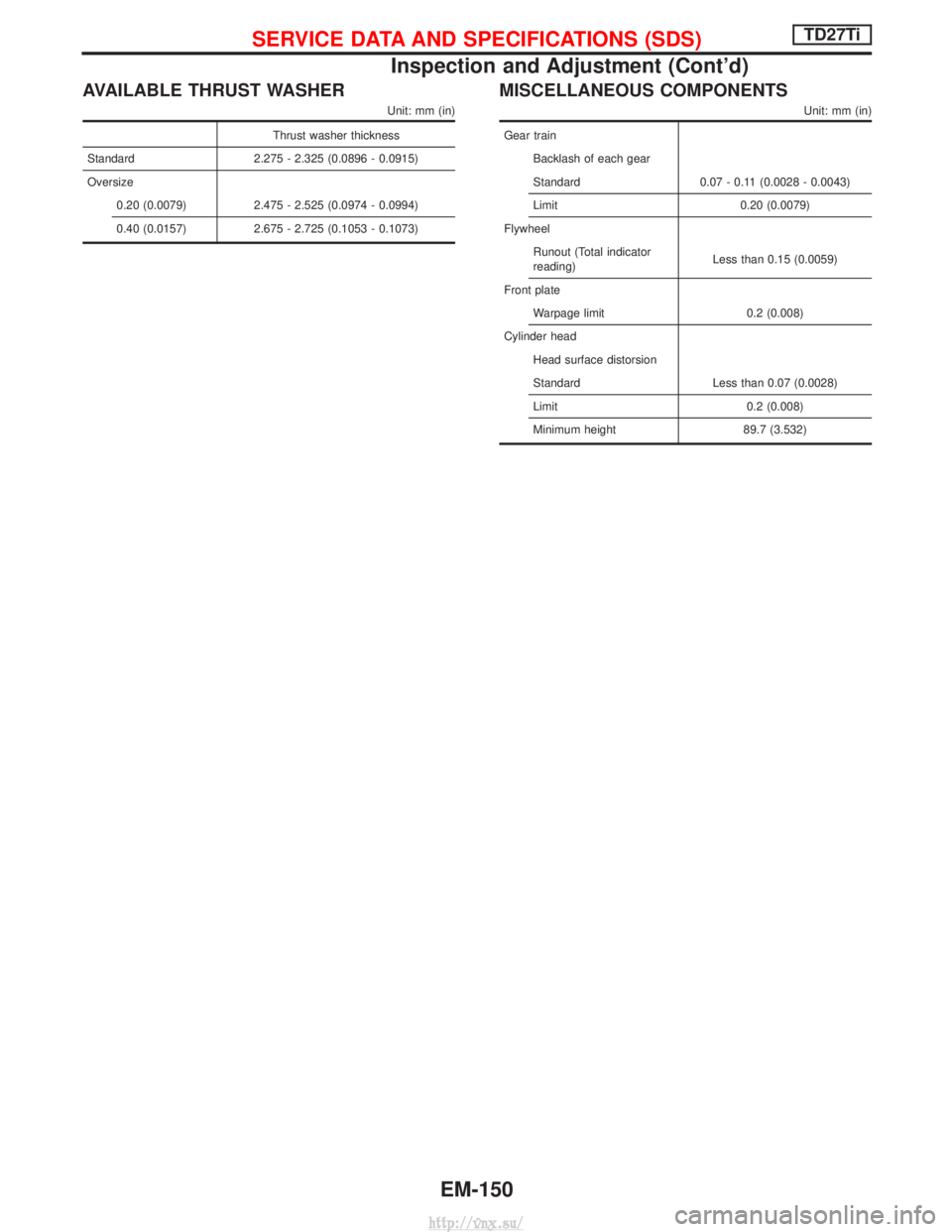
AVAILABLE THRUST WASHER
Unit: mm (in)
Thrust washer thickness
Standard 2.275 - 2.325 (0.0896 - 0.0915)
Oversize 0.20 (0.0079) 2.475 - 2.525 (0.0974 - 0.0994)
0.40 (0.0157) 2.675 - 2.725 (0.1053 - 0.1073)
MISCELLANEOUS COMPONENTS
Unit: mm (in)
Gear trainBacklash of each gear
Standard 0.07 - 0.11 (0.0028 - 0.0043)
Limit 0.20 (0.0079)
Flywheel Runout (Total indicator
reading) Less than 0.15 (0.0059)
Front plate Warpage limit 0.2 (0.008)
Cylinder head Head surface distorsion
Standard Less than 0.07 (0.0028)
Limit 0.2 (0.008)
Minimum height 89.7 (3.532)
SERVICE DATA AND SPECIFICATIONS (SDS)TD27Ti
Inspection and Adjustment (Cont'd)
EM-150
http://vnx.su/
Page 242 of 1833
ENGINE LUBRICATION &COOLING SYSTEMS
SECTION
LC
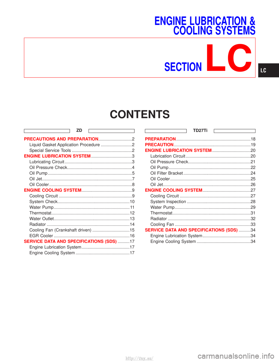
CONTENTS
ZD
PRECAUTIONS AND PREPARATION ............................2
Liquid Gasket Application Procedure ..........................2
Special Service Tools ..................................................2
ENGINE LUBRICATION SYSTEM ..................................3
Lubricating Circuit ........................................................3
Oil Pressure Check......................................................4
Oil Pump ......................................................................5
Oil Jet........................................................................\
...7
Oil Cooler .....................................................................8
ENGINE COOLING SYSTEM ..........................................9
Cooling Circuit .............................................................9
System Check............................................................10
Water Pump ............................................................... 11
Thermostat .................................................................12
Water Outlet ...............................................................13
Radiator .....................................................................14
Cooling Fan (Crankshaft driven) ...............................15
EGR Cooler ...............................................................16
SERVICE DATA AND SPECIFICATIONS (SDS) ..........17
Engine Lubrication System ........................................17
Engine Cooling System .............................................17 TD27TiPREPARATION
..............................................................18
PRECAUTION ................................................................19
ENGINE LUBRICATION SYSTEM ................................20
Lubrication Circuit ......................................................20
Oil Pressure Check....................................................21
Oil Pump ....................................................................22
Oil Filter Bracket ........................................................24
Oil Cooler ...................................................................25
Oil Jet........................................................................\
.26
ENGINE COOLING SYSTEM ........................................27
Cooling Circuit ...........................................................27
System Inspection .....................................................28
Water Pump ...............................................................29
Thermostat .................................................................31
Radiator .....................................................................32
Cooling Fan ...............................................................33
SERVICE DATA AND SPECIFICATIONS (SDS) ..........34
Engine Lubrication System ........................................34
Engine Cooling System .............................................34
http://vnx.su/
Page 243 of 1833

Liquid Gasket Application Procedure
a. Use a scraper to remove all traces of old liquid gasket frommating surfaces and grooves. Also, completely clean any oil
from these areas.
b. Apply a continuous bead of liquid gasket to mating surfaces. (Use Genuine Liquid Gasket or equivalent.)
IFor oil pan, be sure liquid gasket diameter is 3.5 to 4.5 mm
(0.138 to 0.177 in).
I For areas except oil pan, be sure liquid gasket diameter is
2.0 to 3.0 mm (0.079 to 0.118 in).
c. Apply liquid gasket around the inner side of bolt holes (unless otherwise specified).
d. Assembly should be done within 5 minutes after coating.
e. Wait at least 30 minutes before refilling engine oil and engine coolant.
Special Service Tools*: Special tool or commercial equivalent
Tool number
Tool name Description
ST25051001*
Oil pressure gauge
NT558
Measuring oil pressure
Maximum measuring range:
2,452 kPa (24.5 bar, 25
kg/cm
2, 356 psi)
ST25052000*
Hose
NT559
Adapting oil pressure gauge
to cylinder block
EG17650301
Radiator cap tester
adapter
NT564
Adapting radiator cap tester
to radiator filler neck and reser-
voir tank cap
a: 28 (1.10) dia.
b: 31.4 (1.236) dia.
c: 41.3 (1.626) dia.
Unit: mm (in)
SEM164F
AEM080
PRECAUTIONS AND PREPARATIONZD
LC-2
http://vnx.su/
Page 258 of 1833
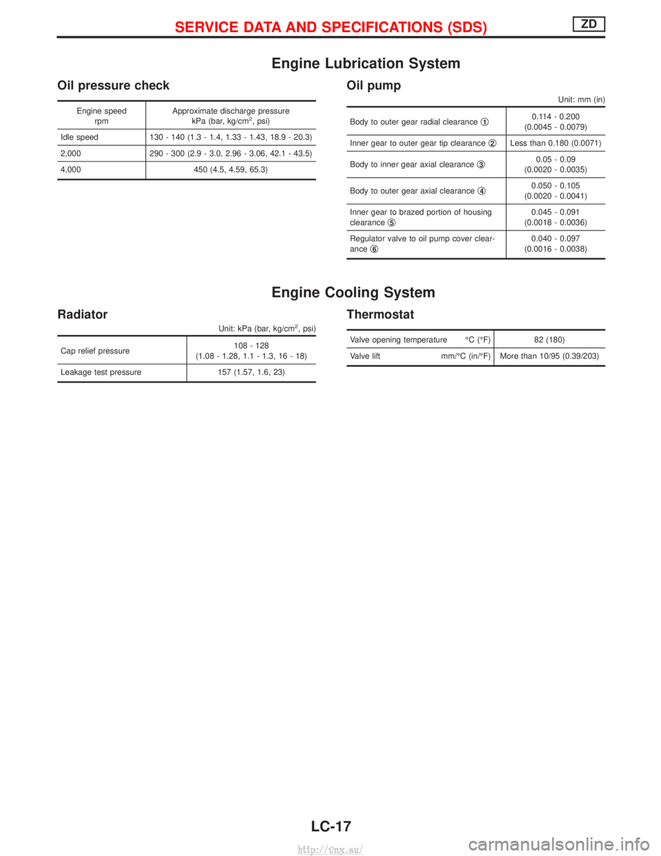
Engine Lubrication System
Oil pressure check
Engine speedrpm Approximate discharge pressure
kPa (bar, kg/cm2, psi)
Idle speed 130 - 140 (1.3 - 1.4, 1.33 - 1.43, 18.9 - 20.3)
2,000 290 - 300 (2.9 - 3.0, 2.96 - 3.06, 42.1 - 43.5)
4,000 450 (4.5, 4.59, 65.3)
Oil pump
Unit: mm (in)
Body to outer gear radial clearance q10.114 - 0.200
(0.0045 - 0.0079)
Inner gear to outer gear tip clearance q
2Less than 0.180 (0.0071)
Body to inner gear axial clearance q
30.05 - 0.09
(0.0020 - 0.0035)
Body to outer gear axial clearance q
40.050 - 0.105
(0.0020 - 0.0041)
Inner gear to brazed portion of housing
clearance q
50.045 - 0.091
(0.0018 - 0.0036)
Regulator valve to oil pump cover clear-
ance q
60.040 - 0.097
(0.0016 - 0.0038)
Engine Cooling System
Radiator
Unit: kPa (bar, kg/cm2, psi)
Cap relief pressure 108 - 128
(1.08 - 1.28, 1.1 - 1.3, 16 - 18)
Leakage test pressure 157 (1.57, 1.6, 23)
Thermostat
Valve opening temperature ÉC (ÉF) 82 (180)
Valve lift mm/ÉC (in/ÉF) More than 10/95 (0.39/203)
SERVICE DATA AND SPECIFICATIONS (SDS)ZD
LC-17
http://vnx.su/
Page 259 of 1833
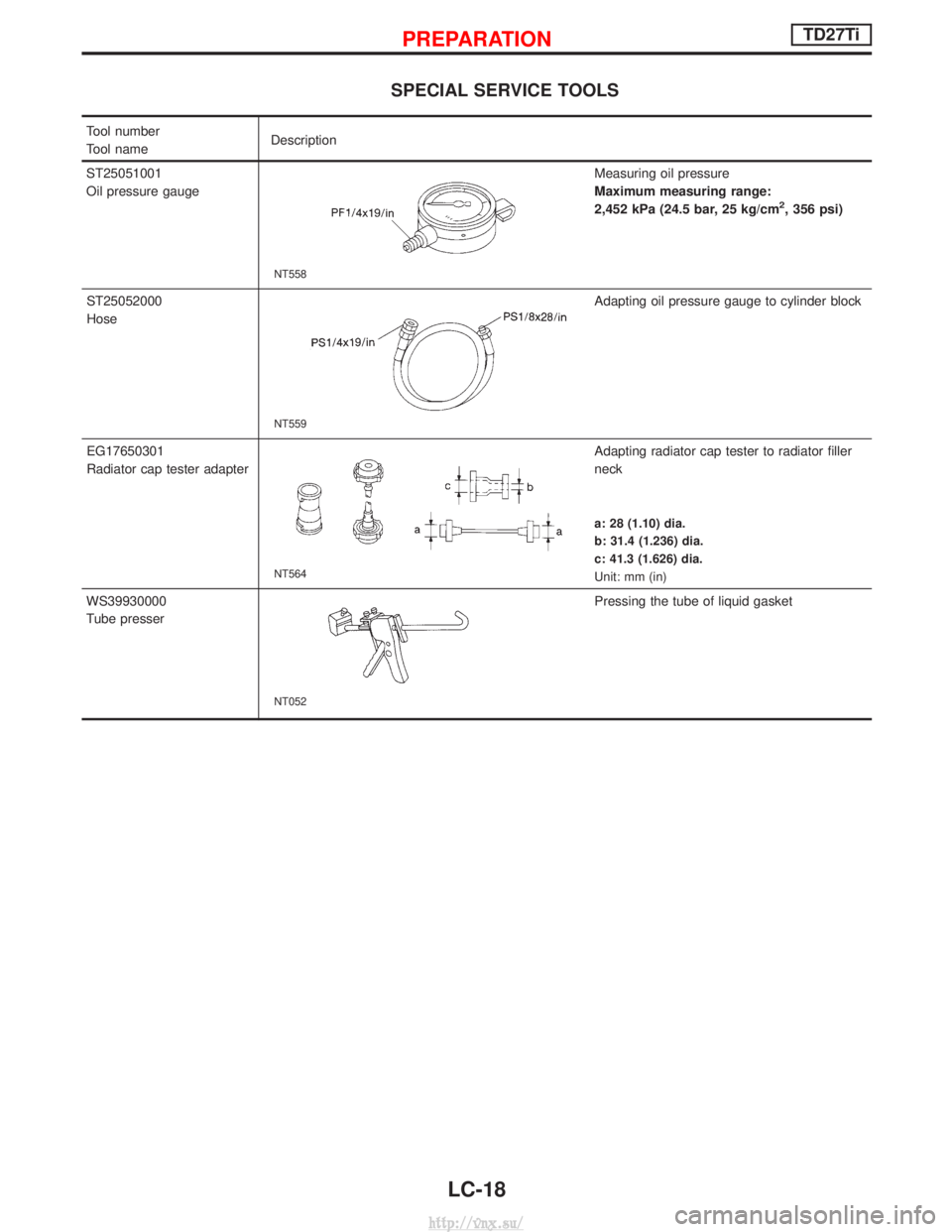
SPECIAL SERVICE TOOLS
Tool number
Tool nameDescription
ST25051001
Oil pressure gauge
NT558
Measuring oil pressure
Maximum measuring range:
2,452 kPa (24.5 bar, 25 kg/cm
2, 356 psi)
ST25052000
Hose
NT559
Adapting oil pressure gauge to cylinder block
EG17650301
Radiator cap tester adapter
NT564
Adapting radiator cap tester to radiator filler
neck
a: 28 (1.10) dia.
b: 31.4 (1.236) dia.
c: 41.3 (1.626) dia.
Unit: mm (in)
WS39930000
Tube presser
NT052
Pressing the tube of liquid gasket
PREPARATIONTD27Ti
LC-18
http://vnx.su/
Page 275 of 1833
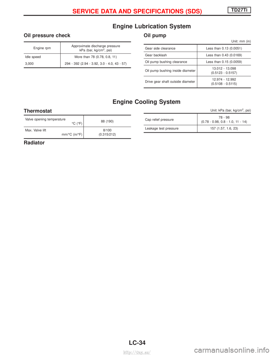
Engine Lubrication System
Oil pressure check
Engine rpmApproximate discharge pressure
kPa (bar, kg/cm2, psi)
Idle speed More than 78 (0.78, 0.8, 11)
3,000 294 - 392 (2.94 - 3.92, 3.0 - 4.0, 43 - 57)
Oil pump
Unit: mm (in)
Gear side clearance Less than 0.13 (0.0051)
Gear backlash Less than 0.43 (0.0169)
Oil pump bushing clearance Less than 0.15 (0.0059)
Oil pump bushing inside diameter 13.012 - 13.098
(0.5123 - 0.5157)
Drive gear shaft outside diameter 12.974 - 12.992
(0.5108 - 0.5115)
Engine Cooling System
Thermostat
Valve opening temperature ÉC (ÉF)88 (190)
Max. Valve lift mm/ÉC (in/ÉF) 8/100
(0.315/212)
Radiator
Unit: kPa (bar, kg/cm2, psi)
Cap relief pressure 78-98
(0.78 - 0.98, 0.8 - 1.0, 11 - 14)
Leakage test pressure 157 (1.57, 1.6, 23)
SERVICE DATA AND SPECIFICATIONS (SDS)TD27Ti
LC-34
http://vnx.su/
Page 276 of 1833
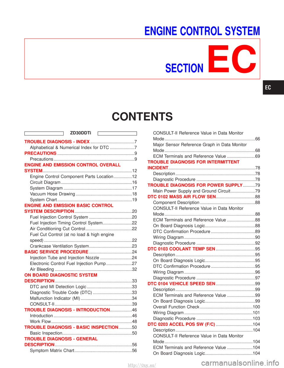
ENGINE CONTROL SYSTEMSECTION
EC
CONTENTS
ZD30DDTi
TROUBLE DIAGNOSIS - INDEX ....................................7
Alphabetical & Numerical Index for DTC ....................7
PRECAUTIONS ...............................................................9
Precautions ..................................................................9
ENGINE AND EMISSION CONTROL OVERALL
SYSTEM ........................................................................\
.12
Engine Control Component Parts Location ...............12
Circuit Diagram ..........................................................16
System Diagram ........................................................17
Vacuum Hose Drawing ..............................................18
System Chart .............................................................19
ENGINE AND EMISSION BASIC CONTROL
SYSTEM DESCRIPTION ...............................................20
Fuel Injection Control System ...................................20
Fuel Injection Timing Control System........................22
Air Conditioning Cut Control ......................................22
Fuel Cut Control (at no load & high engine
speed) ........................................................................\
22
Crankcase Ventilation System ...................................23
BASIC SERVICE PROCEDURE ...................................24
Injection Tube and Injection Nozzle ..........................24
Electronic Control Fuel Injection Pump .....................27
Air Bleeding ...............................................................32
ON BOARD DIAGNOSTIC SYSTEM
DESCRIPTION ...............................................................33
DTC and MI Detection Logic .....................................33
Diagnostic Trouble Code (DTC) ................................33
Malfunction Indicator (MI) ..........................................34
CONSULT-II ...............................................................39
TROUBLE DIAGNOSIS - INTRODUCTION ..................46
Introduction ................................................................46
Work Flow ..................................................................48
TROUBLE DIAGNOSIS - BASIC INSPECTION ...........50
Basic Inspection.........................................................50
TROUBLE DIAGNOSIS - GENERAL
DESCRIPTION ...............................................................56
Symptom Matrix Chart ...............................................56 CONSULT-II Reference Value in Data Monitor
Mode ........................................................................\
..66
Major Sensor Reference Graph in Data Monitor
Mode ........................................................................\
..68
ECM Terminals and Reference Value .......................69
TROUBLE DIAGNOSIS FOR INTERMITTENT
INCIDENT .......................................................................78
Description .................................................................78
Diagnostic Procedure ................................................78
TROUBLE DIAGNOSIS FOR POWER SUPPLY ..........79
Main Power Supply and Ground Circuit ....................79
DTC 0102 MASS AIR FLOW SEN ................................88
Component Description .............................................88
CONSULT-II Reference Value in Data Monitor
Mode ........................................................................\
..88
ECM Terminals and Reference Value .......................88
On Board Diagnosis Logic.........................................88
DTC Confirmation Procedure ....................................89
Wiring Diagram ..........................................................90
Diagnostic Procedure ................................................92
DTC 0103 COOLANT TEMP SEN ................................95
Description .................................................................95
On Board Diagnosis Logic.........................................95
DTC Confirmation Procedure ....................................95
Wiring Diagram ..........................................................96
Diagnostic Procedure ................................................97
DTC 0104 VEHICLE SPEED SEN ................................99
Description .................................................................99
ECM Terminals and Reference Value .......................99
On Board Diagnosis Logic.........................................99
Overall Function Check ...........................................100
Wiring Diagram ........................................................101
Diagnostic Procedure ..............................................103
DTC 0203 ACCEL POS SW (F/C) ..............................104
Description ...............................................................104
CONSULT-II Reference Value in Data Monitor
Mode ........................................................................\
104
ECM Terminals and Reference Value .....................104
On Board Diagnosis Logic.......................................104
http://vnx.su/