Page 93 of 1833

Connecting Rod .........................................................91
Crankshaft..................................................................92
Available Main Bearing ..............................................92
Available Connecting Rod Bearing............................93
Miscellaneous Components.......................................94TD27Ti
PRECAUTIONS.............................................................95
Parts Requiring Angular Tightening ...........................95
Liquid Gasket Application Procedure ........................95
PREPARATION ..............................................................96
Special Service Tools ................................................96
Commercial Service Tools .........................................99
ENGINE COMPONENTS - Outer Parts .....................100
ENGINE COMPONENTS - Internal Parts ..................102
COMPRESSION PRESSURE......................................103 Measurement of Compression Pressure .................103
CYLINDER HEAD ........................................................104 Removal ...................................................................105
Disassembly.............................................................106
Inspection.................................................................107
Assembly ................................................................. 113
Installation ................................................................ 114
OIL SEAL REPLACEMENT ........................................ 117
TURBOCHARGER ....................................................... 119
Removal and Installation ......................................... 119
Inspection................................................................. 119
ENGINE REMOVAL .....................................................123
ENGINE OVERHAUL ..................................................125
Disassembly.............................................................125
Inspection.................................................................127
Assembly .................................................................138
SERVICE DATA AND SPECIFICATIONS (SDS) ........143
General Specifications .............................................143
Inspection and Adjustment ......................................144
CONTENTS(Cont'd)
EM-2
http://vnx.su/
Page 95 of 1833
Special Service Tools
Tool number
Tool nameDescription
ST0501S000
Engine stand assembly
q
1ST05011000
Engine stand
q
2ST05012000
Base
NT042
Disassembling and assembling
KV10106500
Engine stand shaft
NT028
KV11106101
Engine sub-attachment
NT819
KV10115600
Valve oil seal drift
NT603
Installing valve oil seal
Use side A.
Side A
a: 20 (0.79) dia.
b: 13 (0.51) dia.
c: 10.3 (0.406) dia.
d: 8 (0.31) dia.
e: 10.7 (0.421)
f: 5 (0.20)
Unit: mm (in)
KV10107902
Valve oil seal puller
q
1KV10116100
Valve oil seal puller
adapter
NT605
Removing valve oil seal
KV101056S0
Ring gear stopper
q
1KV10105630
Adapter
q
2KV10105610
Plate
NT617
Preventing crankshaft from rotating
a: 3 (0.12)
b: 6.4 (0.252)
c: 2.8 (0.110)
d: 6.6 (0.260)
e: 107 (4.21)
f: 14 (0.55)
g: 20 (0.79)
h: 14 (0.55) dia.
Unit: mm (in)
PREPARATIONZD
EM-4
http://vnx.su/
Page 96 of 1833
Tool number
Tool nameDescription
KV101151S0
Lifter stopper set
q
1KV10115110
Camshaft pliers
q
2KV10115120
Lifter stopper
NT041
Changing shims
KV101092S0
Valve spring compressor
q
1KV10109210
Compressor
q
2KV10109220
Adapter
NT718
Disassembling and assembling valve compo-
nents
ED19600620
Compression gauge adapter
NT820
Checking compression pressure
ST16610000
Pilot bushing puller
NT045
Removing crankshaft pilot bushing
KV101111 0 0
Seal cutter
NT046
Removing steel oil pan and rear timing chain
case
WS39930000
Tube presser
NT052
Pressing the tube of liquid gasket
KV10112100
Angle wrench
NT014
Tightening bolts for bearing cap, cylinder head,
etc.
PREPARATIONZD
Special Service Tools (Cont'd)
EM-5
http://vnx.su/
Page 97 of 1833
Tool number
Tool nameDescription
KV10109300
Pulley holder
NT628a: 68 mm (2.68 in)
b: 8 mm (0.31 in) dia.
KV111045S1
Balancer shaft bearing
replacer set
q
1KV11104510
Replacer bar
q
2KV11104521
Guide plate
q
3KV11104530
Adapter
(Front bearing)
q
4ST15243000
Drift
NT258
Removing and installing balancer shaft bearing
Commercial Service Tools
Tool name Description
Valve seat cutter set
NT048
Finishing valve seat dimensions
Piston ring compressor
NT044
Installing piston assembly into cylinder bore
Piston ring expander
NT030
Removing and installing piston ring
Standard Universal
NT808
Removing and installing transmission mount
PREPARATIONZD
Special Service Tools (Cont'd)
EM-6
http://vnx.su/
Page 98 of 1833
Tool nameDescription
Deep socket (12 mm)
NT821
Removing and installing glow plugs
PREPARATIONZD
Commercial Service Tools (Cont'd)
EM-7
http://vnx.su/
Page 113 of 1833
Removal and Installation
REMOVAL
1. Drain engine oil.
2. Remove the following parts.
IUnder guard
I Crossmember, differential member, front final drive assembly
I Engine gusset
3. Loosen and remove oil pan installation bolts in reverse order of numbers in the figure.
4. Use a seal cutter (special service tool) to cut away liquid gas- ket and remove oil pan.
5. Remove oil strainer.
YEM064
JEM773G
OIL PAN & OIL STRAINERZD
EM-22
http://vnx.su/
Page 122 of 1833

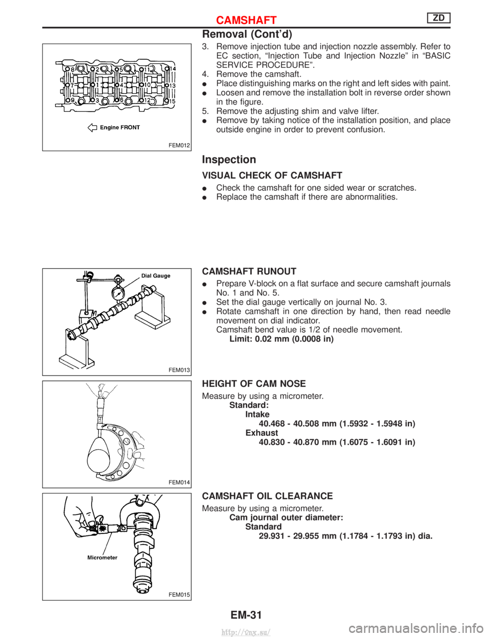
3. Remove injection tube and injection nozzle assembly. Refer toEC section, ªInjection Tube and Injection Nozzleº in ªBASIC
SERVICE PROCEDUREº.
4. Remove the camshaft.
I Place distinguishing marks on the right and left sides with paint.
I Loosen and remove the installation bolt in reverse order shown
in the figure.
5. Remove the adjusting shim and valve lifter.
I Remove by taking notice of the installation position, and place
outside engine in order to prevent confusion.
Inspection
VISUAL CHECK OF CAMSHAFT
ICheck the camshaft for one sided wear or scratches.
I Replace the camshaft if there are abnormalities.
CAMSHAFT RUNOUT
IPrepare V-block on a flat surface and secure camshaft journals
No. 1 and No. 5.
I Set the dial gauge vertically on journal No. 3.
I Rotate camshaft in one direction by hand, then read needle
movement on dial indicator.
Camshaft bend value is 1/2 of needle movement.
Limit: 0.02 mm (0.0008 in)
HEIGHT OF CAM NOSE
Measure by using a micrometer. Standard:Intake40.468 - 40.508 mm (1.5932 - 1.5948 in)
Exhaust 40.830 - 40.870 mm (1.6075 - 1.6091 in)
CAMSHAFT OIL CLEARANCE
Measure by using a micrometer. Cam journal outer diameter:Standard29.931 - 29.955 mm (1.1784 - 1.1793 in) dia.
FEM012
FEM013
FEM014
FEM015
CAMSHAFTZD
Removal (Cont'd)
EM-31
http://vnx.su/
Page 141 of 1833

VALVE OIL SEAL
1. Remove timing chain. Refer to EM-26, ªTIMING CHAINº.
2. Remove injection nozzle assembly. Refer to ªInjection Tube andInjection Nozzleº in ªBASIC SERVICE PROCEDUREº in EC
section.
3. Remove camshaft. Refer to EM-30, ªCAMSHAFTº.
4. Remove valve lifters and mark order No. on each lifter.
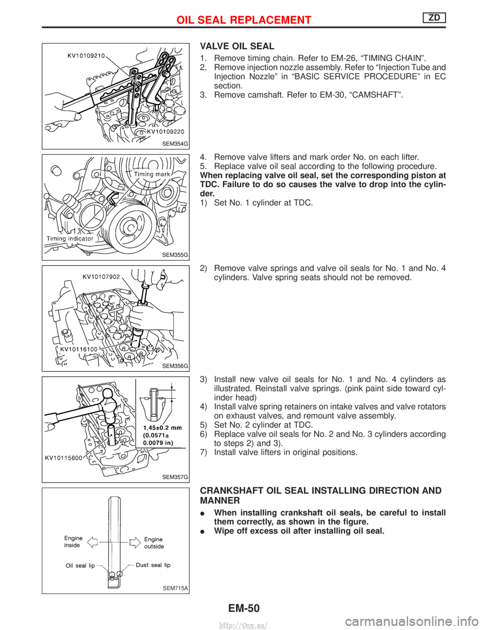
5. Replace valve oil seal according to the following procedure.
When replacing valve oil seal, set the corresponding piston at
TDC. Failure to do so causes the valve to drop into the cylin-
der.
1) Set No. 1 cylinder at TDC.
2) Remove valve springs and valve oil seals for No. 1 and No. 4 cylinders. Valve spring seats should not be removed.
3) Install new valve oil seals for No. 1 and No. 4 cylinders as illustrated. Reinstall valve springs. (pink paint side toward cyl-
inder head)
4) Install valve spring retainers on intake valves and valve rotators on exhaust valves, and remount valve assembly.
5) Set No. 2 cylinder at TDC.
6) Replace valve oil seals for No. 2 and No. 3 cylinders according to steps 2) and 3).
7) Install valve lifters in original positions.
CRANKSHAFT OIL SEAL INSTALLING DIRECTION AND
MANNER
I When installing crankshaft oil seals, be careful to install
them correctly, as shown in the figure.
I Wipe off excess oil after installing oil seal.
SEM354G
SEM355G
SEM356G
SEM357G
SEM715A
OIL SEAL REPLACEMENTZD
EM-50
http://vnx.su/