Page 710 of 1833
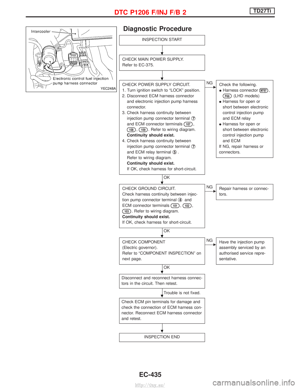
Diagnostic Procedure
INSPECTION START
CHECK MAIN POWER SUPPLY.
Refer to EC-375.
CHECK POWER SUPPLY CIRCUIT.
1. Turn ignition switch to ªLOCKº position.
2. Disconnect ECM harness connector and electronic injection pump harness
connector.
3. Check harness continuity between injection pump connector terminal q
7
and ECM connector terminals107,
108,109. Refer to wiring diagram.
Continuity should exist.
4. Check harness continuity between injection pump connector terminal q
7
and ECM relay terminalq5.
Refer to wiring diagram.
Continuity should exist.
If OK, check harness for short-circuit.
OK
ENG Check the following.
IHarness connector
M787,
F66(LHD models)
I Harness for open or
short between electronic
control injection pump
and ECM relay
I Harness for open or
short between electronic
control injection pump
and ECM
If NG, repair harness or
connectors.
CHECK GROUND CIRCUIT.
Check harness continuity between injec-
tion pump connector terminal q
4and
ECM connector terminals
101,102,
103. Refer to wiring diagram.
Continuity should exist.
If OK, check harness for short-circuit.
OK
ENG Repair harness or connec-
tors.
CHECK COMPONENT
(Electric governor).
Refer to ªCOMPONENT INSPECTIONº on
next page.
OK
ENGHave the injection pump
assembly serviced by an
authorised service repre-
sentative.
Disconnect and reconnect harness connec-
tors in the circuit. Then retest.
Trouble is not fixed.
Check ECM pin terminals for damage and
check the connection of ECM harness con-
nector. Reconnect ECM harness connector
and retest.
INSPECTION END
YEC248A
H
H
H
H
H
H
H
DTC P1206 F/INJ F/B 2TD27Ti
EC-435
http://vnx.su/
Page 715 of 1833
qA
CHECK COMPONENT
(Control sleeve position sensor).
Refer to ªCOMPONENT INSPECTIONº on
page EC-440.
OK
ENGHave the injection pump
assembly serviced by an
authorised service repre-
sentative.
Disconnect and reconnect harness con-
nectors in the circuit. Then retest.
Trouble is not fixed.
Check ECM pin terminals for damage and
check the connection of ECM harness
connector. Reconnect ECM harness con-
nector and retest.
INSPECTION END
Component Inspection
CONTROL SLEEVE POSITION SENSOR
1. Disconnect control sleeve position sensor & electric governor harness connector.
2. Check continuity between terminals q
1andq3,q2and q3.
Resistance: Approximately 6.1W [at 25ÉC (77ÉF)]
If NG, take proper action.
YEC259A
H
H
H
H
DTC P1207 CONT SLEEV POS SENTD27Ti
Diagnostic Procedure (Cont'd)
EC-440
http://vnx.su/
Page 751 of 1833

General Specifications
Engine speed
Unit: rpm
EngineTD27Ti
Idle speed A/C: ON 725
845
Maximum engine speed 5,500
Pump numbers
Engine Part numberPump assembly num-
ber
TD27Ti 16700 7F406 A 460 801 135
Pump data is not yet available.
Refer to CALIBRATION STANDARD published
by BOSCH.
Injection Nozzle
INSPECTION AND ADJUSTMENT
Injection nozzle assembly
Unit: kPa (bar, kg/cm2, psi)
Initial injection pressure
New 12,749 - 13,730 (127.5 - 137.3, 130 - 140,
1,849 - 1,991)
Used 12,259 - 12,749 (122.6 - 127.5, 120 - 135,
1,706 - 1,849)
Inspection and Adjustment
Plunger lift mm (in)
at TDC 0.275 0.02
(0.0108) (0.0008)
Idle speed rpm
(ªNº or ªPº position) 725 25
MASS AIR FLOW SENSOR
Supply voltage
V Approximately 5
Output voltage V1.5 - 2.7*
*: Engine is warmed up sufficiently and idling under no-load.
ENGINE COOLANT TEMPERATURE
SENSOR
Temperature ÉC (ÉF) Resistance kW
20 (68) 2.1 - 2.9
50 (122) 0.68 - 1.00
90 (194) 0.236 - 0.260
CONTROL SLEEVE POSITION SENSOR
Resistance [at 25ÉC (77ÉF)] WApproximately 6.1
INJECTION TIMING CONTROL VALVE
Resistance [at 25ÉC (77ÉF)] WApproximately 15
NEEDLE LIFT SENSOR
Resistance [at 25ÉC (77ÉF)] WApproximately 105
CRANKSHAFT POSITION SENSOR (TDC)
Resistance [at 25ÉC (77ÉF)] WApproximately 900
GLOW PLUG
Resistance [at 25ÉC (77ÉF)] W0.5
ACCELERATOR POSITION SENSOR
Throttle valve conditions Resistance kW
[at 25ÉC (77ÉF)]
Completely closed Approximately 1.2
Partially open 1.2 - 1.9
Completely open Approximately 1.9
FUEL TEMPERATURE SENSOR
Temperature ÉC (ÉF)Resistance kW
25 (77) Approximately 1.9
SERVICE DATA AND SPECIFICATIONS (SDS)TD27Ti
EC-476
http://vnx.su/
Page 753 of 1833
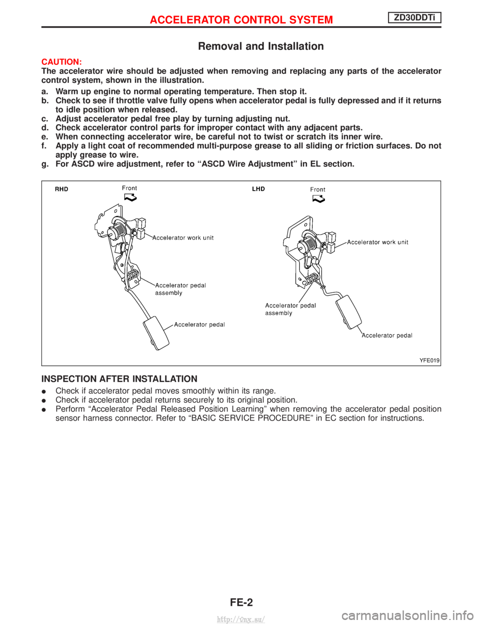
Removal and Installation
CAUTION:
The accelerator wire should be adjusted when removing and replacing any parts of the accelerator
control system, shown in the illustration.
a. Warm up engine to normal operating temperature. Then stop it.
b. Check to see if throttle valve fully opens when accelerator pedal is fully depressed and if it returnsto idle position when released.
c. Adjust accelerator pedal free play by turning adjusting nut.
d. Check accelerator control parts for improper contact with any adjacent parts.
e. When connecting accelerator wire, be careful not to twist or scratch its inner wire.
f. Apply a light coat of recommended multi-purpose grease to all sliding or friction surfaces. Do not apply grease to wire.
g. For ASCD wire adjustment, refer to ªASCD Wire Adjustmentº in EL section.
INSPECTION AFTER INSTALLATION
I Check if accelerator pedal moves smoothly within its range.
I Check if accelerator pedal returns securely to its original position.
I Perform ªAccelerator Pedal Released Position Learningº when removing the accelerator pedal position
sensor harness connector. Refer to ªBASIC SERVICE PROCEDUREº in EC section for instructions.
YFE019
ACCELERATOR CONTROL SYSTEMZD30DDTi
FE-2
http://vnx.su/
Page 756 of 1833
Adjusting Accelerator Cable
q1Pedal bracket
q
2Accelerator switch q
3Accelerator position sensor
q
4Accelerator cable q
5Return spring
q
6Accelerator pedal
INSPECTION AFTER INSTALLATION
I Check if accelerator pedal moves smoothly within its range.
I Check if accelerator pedal returns securely to its original position.
I Perform ªAccelerator Pedal Released Position Learningº when removing the accelerator pedal position
sensor harness connector. Refer to ªBASIC SERVICE PROCEDUREº in EC section for instructions.
I If MI illuminates after engine has started, refer to ªON BOARD DIAGNOSTIC SYSTEM DESCRIPTIONº
in EC section for instructions.
NFE032
ACCELERATOR CONTROL SYSTEMTD27Ti
FE-5
http://vnx.su/
Page 758 of 1833
WARNING:
When replacing fuel line parts, be sure to observe the following:
IDisplay a ªCAUTION: INFLAMMABLEº sign in workshop.
I Be sure to furnish workshop with a CO
2fire extinguisher service.
I Do not smoke while servicing fuel system. Keep open flames and sparks away from work area.
I Be sure to disconnect battery ground cable before conducting operations.
I Pour drained fuel into an explosion-proof container, then ensure container lid is installed securely.
CAUTION:
I For ECM models, release fuel pressure from fuel line. Refer to EC section (ªFuel Pressure Releaseº,
ªBASIC SERVICE PROCEDUREº).
I Do not disconnect any fuel line unless absolutely necessary.
I Plug hose and pipe openings to prevent entry of dust or dirt.
I Always replace top lid seal and hose clamps with new ones.
I Do not kink or twist hoses and tubes during installation.
I Do not tighten hose clamps excessively because this could cause damage to the hose.
I Ensure fuel check valve is installed in the correct orientation.
I Refer to EC section (ªFUEL CHECK VALVEº, ªEVAPORATIVE EMISSION SYSTEMº).
I After installation, run engine and check for fuel leaks at connections.
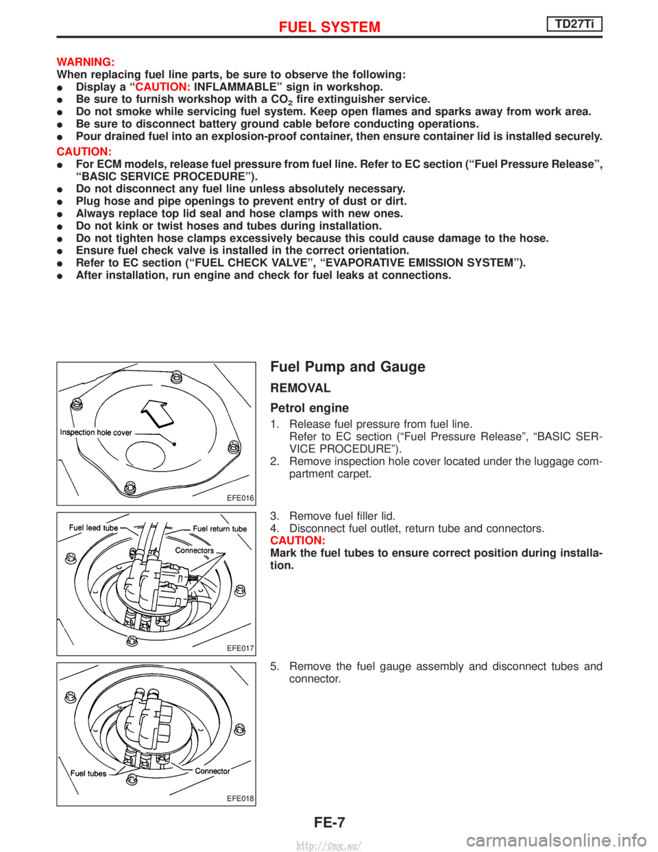
Fuel Pump and Gauge
REMOVAL
Petrol engine
1. Release fuel pressure from fuel line.
Refer to EC section (ªFuel Pressure Releaseº, ªBASIC SER-
VICE PROCEDUREº).
2. Remove inspection hole cover located under the luggage com- partment carpet.
3. Remove fuel filler lid.
4. Disconnect fuel outlet, return tube and connectors.
CAUTION:
Mark the fuel tubes to ensure correct position during installa-
tion.
5. Remove the fuel gauge assembly and disconnect tubes and connector.
EFE016
EFE017
EFE018
FUEL SYSTEMTD27Ti
FE-7
http://vnx.su/
Page 764 of 1833
CLUTCH
SECTION
CL
CONTENTS
PRECAUTIONS AND PREPARATION ............................2
Precautions ..................................................................2
Preparation ..................................................................2
CLUTCH SYSTEM ...........................................................3
Clutch Pedal ................................................................4
INSPECTION AND ADJUSTMENT .................................5
Adjusting Clutch Pedal ................................................5
Bleeding Procedure .....................................................6
CLUTCH MASTER CYLINDER .......................................7
HYDRAULIC CLUTCH CONTROL .................................8Clutch Master Cylinder ................................................8
Clutch Operating Cylinder ...........................................8
CLUTCH RELEASE MECHANISM .................................9
CLUTCH DISC AND CLUTCH COVER ........................ 11
Clutch Disc................................................................. 11
Clutch Cover and Flywheel .......................................12
SERVICE DATA AND SPECIFICATIONS (SDS) ..........14
General Specifications ...............................................14
Inspection and Adjustment ........................................14
http://vnx.su/
Page 765 of 1833
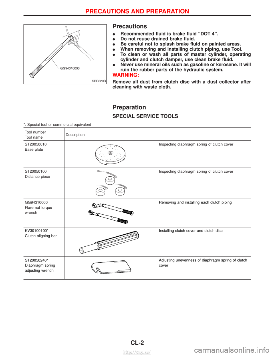
Precautions
IRecommended fluid is brake fluid ªDOT 4º.
I Do not reuse drained brake fluid.
I Be careful not to splash brake fluid on painted areas.
I When removing and installing clutch piping, use Tool.
I To clean or wash all parts of master cylinder, operating
cylinder and clutch damper, use clean brake fluid.
I Never use mineral oils such as gasoline or kerosene. It will
ruin the rubber parts of the hydraulic system.
WARNING:
Remove all dust from clutch disc with a dust collector after
cleaning with waste cloth.
Preparation
SPECIAL SERVICE TOOLS
*: Special tool or commercial equivalent
Tool number
Tool name Description
ST20050010
Base plate
Inspecting diaphragm spring of clutch cover
ST20050100
Distance piece
Inspecting diaphragm spring of clutch cover
GG94310000
Flare nut torque
wrench
Removing and installing each clutch piping
KV30100100*
Clutch aligning bar
Installing clutch cover and clutch disc
ST20050240*
Diaphragm spring
adjusting wrench
Adjusting unevenness of diaphragm spring of clutch
cover
SBR820B
PRECAUTIONS AND PREPARATION
CL-2
http://vnx.su/