Page 229 of 3870

YES: Repair or replace the damaged components(s). Then go to Step 8 .
NO: An open circuit may be present in the ground circuit. Repair the
wiring harness between ABS-ECU connector A-02 terminals 2, 18 and the
body ground. Then go to Step 8 .
STEP 5. Check the battery.
Check the battery (Refer to BATTERY TEST
).
Q: Is the battery in good condition?
YES: Go to Step 6.
NO: Charge or replace the battery. Then go to Step 8 .
STEP 6. Check the charging system.
Check the charging system (Refer to GENERATORS & REGULATORS
).
Q: Is the charging system in good condition?
YES: Go to Step 7.
NO: Repair or replace the charging system component(s).
Then go to Step 8 .
STEP 7. Retest the system.
Q: Can the ABS-ECU communicate with the scan tool (MUT-III Sub
Assembly)?
YES: It can be assumed that this malfunction is intermittent. Refer to
HOW TO COPE WITH INTERMITTENT MALFUNCTIONS
.
NO: Replace the ABS-ECU. Then go to Step 8.
STEP 8. Retest the system.
Q: Can the ABS-ECU communicate with the scan tool (MUT-III Sub
Assembly)?
2004 Mitsubishi Endeavor LS
2004 BRAKES Anti-Lock Braking System (ABS) - Endeavor
Page 232 of 3870
Fig. 134: EBO And ABS Warning Light Circuit Diagram
Courtesy of MITSUBISHI MOTOR SALES OF AMERICA.
Fig. 135: Identifying Connectors: A
-02, C
-04, C
-31, C
-101, C
-102, C
-103, C
-
211, C
-215
Courtesy of MITSUBISHI MOTOR SALES OF AMERICA.
TECHNICAL DESCRIPTION (COMMENT)
The ABS-ECU sends the ABS warning light and the brake warning light
signals to the combination meter via the CAN communication. This may be caused by faults in the CAN bus line, the combination meter or
the ABS-ECU.
TROUBLESHOOTING HINTS (THE MOST LIKELY CAUSES FOR THIS CASE:)
Damaged wiring harness or connector Combination meter defect Malfunction of the hydraulic unit (integrated with ABS-ECU)
DIAGNOSIS
2004 Mitsubishi Endeavor LS
2004 BRAKES Anti-Lock Braking System (ABS) - Endeavor
Page 243 of 3870
Fig. 141: Checking Terminal Voltage
Courtesy of MITSUBISHI MOTOR SALES OF AMERICA.
2. The terminal layouts are shown in the illustrations below.
Fig. 142: Signal Specification
Courtesy of MITSUBISHI MOTOR SALES OF AMERICA.
RESISTANCE AND CONTINUITY BETWEEN HARNESS-SIDE CONNECTOR TERMINALS 1. Disconnect the connector A-02, and connect special tool ABS Check Harness
(MB991970) to the wiring harness-side connector.
2. Measure the resistance and continuity between the terminals indicated in the
table below. NOTE: Do not measure terminal voltage for approximately three
seconds after the ignition switch is turned "ON." The ABS-
ECU performs the initial check during that period.
NOTE: Do not connect special tool ABS Check Harness
(MB991970) to the ABS-ECU.
2004 Mitsubishi Endeavor LS
2004 BRAKES Anti-Lock Braking System (ABS) - Endeavor
Page 278 of 3870

On-vehicle Deployment 1. Before proceeding, see
AIR BAG SAFETY PRECAUTIONS
. Move vehicle
to an isolated area. Open all doors and windows. Disconnect and shield
negative battery cable end. Disconnect positive battery cable. Remove battery
from vehicle. Wait at least 60 seconds before continuing.
2. To deploy driver-side air bag module, remove steering column lower cover.
Disconnect lower clockspring Yellow 4-pin connector. Cut harness side of
connector from wire harness and strip ends of driver-side air bag module wires
on harness side of clockspring connector. See
WIRING DIAGRAMS
.
3. To deploy passenger-side air bag module, remove glove box and glove box
outer case. Disconnect passenger-side air bag module Red connector.
4. To deploy side impact air bag module, disconnect appropriate side impact air
bag module Red connector, located under front seat.
5. To deploy seat belt pretensioner, disconnect appropriate seat belt pretensioner
connector, located at seat belt pretensioner.
6. Fabricate a de
ployment harness usin
g two wires at least 20 feet
(6.1 m
) in
WARNING:Air bag modules and seat belt pretensioners make
loud noises during deployment. Air bag module and
seat belt pretensioner deployment could cause
personal injury. Always deploy components
outdoors and away from people. Never deploy air
bag modules with trim cover face down.
NOTE: If vehicle is to be scrapped, perform On-vehicle
deployment. See ON
-VEHICLE DEPLOYMENT
. If vehicle
will continue to be operated, perform Off-vehicle
Deployment. See OFF
-VEHICLE DEPLOYMENT
.
NOTE: Driver-side and passenger-side air bag modules will be
either single-stage or dual-stage. Consult wiring
diagrams to ensure correct wires are cut and spliced
prior to deployment. See WIRING DIAGRAMS
.
2004 Mitsubishi Endeavor Limited
2004 ACCESSORIES/SAFETY EQUIPMENT Mitsubishi - Air Bag Restraint Systems
Page 279 of 3870

length. Strip insulation from ends of wires. Connect wires at one end of harness
to clockspring connector stripped wires and cover connections with insulating
tape. Temporarily wrap other end of harness wires together to prevent
unexpected air bag deployment.
7. Stretch deployment harness as far away from vehicle as possible. Roll up
vehicle windows to lessen deployment noise and cover vehicle with car cover,
in case glass should shatter during deployment. Ensure area is clear of people.
Untwist deployment harness wire ends. Touch wire ends to 12 volt battery
terminals to deploy driver-side air bag module.
8. Repeat procedure for remaining air bag modules and seat belt pretensioners.
Use SRS Air Bag Adapter Harness (MB686560) for passenger-side and side
impact air bag modules. Use SRS Adapter Harness (MR991885) for seat belt
pretensioners. If any component fails to deploy, stay away from vehicle and
contact manufacturer for further instructions. Allow 30 minutes for air bag
modules to cool.
Off-vehicle Deployment 1. Before proceeding, see
AIR BAG SAFETY PRECAUTIONS
. Turn ignition
switch to LOCK position. Disconnect negative battery cable. Shield cable end.
Wait at least 60 seconds before continuing. Disconnect positive battery cable.
Remove battery from vehicle.
2. Fabricate a deployment harness using two wires at least 20 feet (6.1 m) in
length. Strip insulation from ends of wires. Twist together one end of wires
temporarily. Remove driver-side air bag module. See
DRIVER
-SIDE AIR
BAG MODULE & CLOCKSPRING
under REMOVAL &
INSTALLATION. Place driver-side air bag module on surface face up. Touch
vehicle body with bare hands to discharge static electricity from body. Cut
driver-side air bag module connector from pigtail leads. Strip insulation from
ends of
pigtail wires. Attach remainin
g ends of de
ployment harness to
pigtail NOTE: Driver-side and passenger-side air bag modules will be
either single-stage or dual-stage. Consult wiring
diagrams to ensure correct wires are cut and spliced
prior to deployment. See WIRING DIAGRAMS
.
2004 Mitsubishi Endeavor Limited
2004 ACCESSORIES/SAFETY EQUIPMENT Mitsubishi - Air Bag Restraint Systems
Page 294 of 3870
slide sensor.
3. To install, reverse removal procedure. Tighten seat slide sensor bolt and front
seat bolts to specification. See TORQUE SPECIFICATIONS
. Activate air
bag system.
Fig. 13: Identifying Seat Slide Sensor
Courtesy of MITSUBISHI MOTOR SALES OF AMERICA.
SIDE IMPACT AIR BAG MODULE Removal & Installation 1. Before proceeding, see AIR BAG SAFETY PRECAUTIONS
. Disable air
bag system. See DISABLING & ACTIVATING AIR BAG SYSTEM
.
2. Disconnect wiring under appropriate front seat. Remove seat nuts and bolts.
Remove seat from vehicle. Remove bolts securing seat back assembly to seat
recliner hin
ges. Remove front seat back assembl
y.
NOTE: Side impact air bag module is replaced with seat back
assembly and cannot be serviced separately.
2004 Mitsubishi Endeavor Limited
2004 ACCESSORIES/SAFETY EQUIPMENT Mitsubishi - Air Bag Restraint Systems
Page 298 of 3870
ADJUSTMENTS CENTERING CLOCKSPRING (DUAL-STAGE AIR BAG SYSTEM) Turn clockspring fully clockwise, then turn counterclockwise about 3 turns to align
mating marks. See Fig. 17
. Clockspring is now centered.
Fig. 17: Aligning Clockspring Mating Marks (Single
-sta
ge Clocks
prin
g Shown,
Dual
-stage Clockspring Is Similar)
Courtesy of MITSUBISHI MOTOR SALES OF AMERICA.
WIRE REPAIR DO NOT repair SRS wiring harness or connectors. If SRS wiring or harness
connectors are faulty, replace wiring harness. TORQUE SPECIFICATION
S
2004 Mitsubishi Endeavor Limited
2004 ACCESSORIES/SAFETY EQUIPMENT Mitsubishi - Air Bag Restraint Systems
Page 309 of 3870

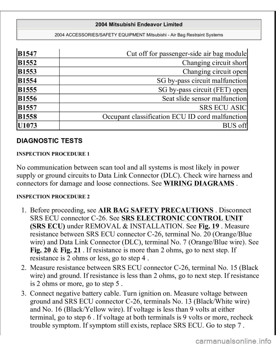
DIAGNOSTIC TESTS INSPECTION PROCEDURE 1 No communication between scan tool and all systems is most likely in power
supply or ground circuits to Data Link Connector (DLC). Check wire harness and
connectors for damage and loose connections. See WIRING DIAGRAMS
.
INSPECTION PROCEDURE 2 1. Before proceeding, see AIR BAG SAFETY PRECAUTIONS
. Disconnect
SRS ECU connector C-26. See SRS ELECTRONIC CONTROL UNIT
(SRS ECU)
under REMOVAL & INSTALLATION. See Fig. 19
. Measure
resistance between SRS ECU connector C-26, terminal No. 20 (Orange/Blue
wire) and Data Link Connector (DLC), terminal No. 7 (Orange/Blue wire). See
Fig. 20
& Fig. 21
. If resistance is more than 2 ohms, go to next step. If
resistance is 2 ohms or less, go to step 4 .
2. Measure resistance between SRS ECU connector C-26, terminal No. 15 (Black
wire) and ground. If resistance is less than 2 ohms, go to next step. If resistance
is 2 ohms or more, go to step 5 .
3. Connect negative battery cable. Turn ignition on. Measure voltage between
ground and SRS ECU connector C-26, terminals No. 13 (Black/White wire)
and No. 16 (Black/Yellow wire). If voltage is less than 9 volts at either
terminal, go to step 6 . If voltage at both terminals is 9 volts or more, recheck
trouble s
ymptom. If s
ymptom still exists, re
place SRS ECU. Go to ste
p 7 .
B1547
Cut off for passenger-side air bag module
B1552
Changing circuit short
B1553
Changing circuit open
B1554
SG by-pass circuit malfunction
B1555
SG by-pass circuit (FET) open
B1556
Seat slide sensor malfunction
B1557
SRS ECU ASIC
B1558
Occupant classification ECU ID cord malfunction
U1073
BUS of
f
2004 Mitsubishi Endeavor Limited
2004 ACCESSORIES/SAFETY EQUIPMENT Mitsubishi - Air Bag Restraint Systems