2004 MITSUBISHI ENDEAVOR wiring
[x] Cancel search: wiringPage 327 of 3870
with fuse No. 23. See WIRING DIAGRAMS
. If continuity does not exist, go
to next step.
7. Check wire harness between connector C-211, terminal No. 25 and
combination meter connector C-102, terminal No. 12 for a short to ground. See
Fig. 27
. If wire harness is okay, go to step 10 . If wire harness is not okay,
repair wire harness. Go to step 10 .
8. Disconnect SRS ECU connector C-26. Check for continuity between SRS ECU
connector C-26, terminal No. 16 (Black/Yellow wire) and ground. If continuity
exists, go to next step. If continuity does not exist, erase, then retrieve DTCs
using scan tool. If DTC 41 is retrieved, replace SRS ECU. Go to step 10 .
9. Check Black/Yellow wire between SRS ECU connector C-26, terminal No. 16
and junction block connector C-211, terminal No. 24 for damage or an open or
short circuit. If wire is okay, go to next step. If wire is not okay, replace wire
harness and go to next step.
10. Reconnect all SRS components. Activate air bag system. Using scan tool, erase
then retrieve DTCs. If DTC 41 is retrieved, go to step 1 . If DTC 41 is not
retrieved, system is normal at this time. Intermittent condition may exist.
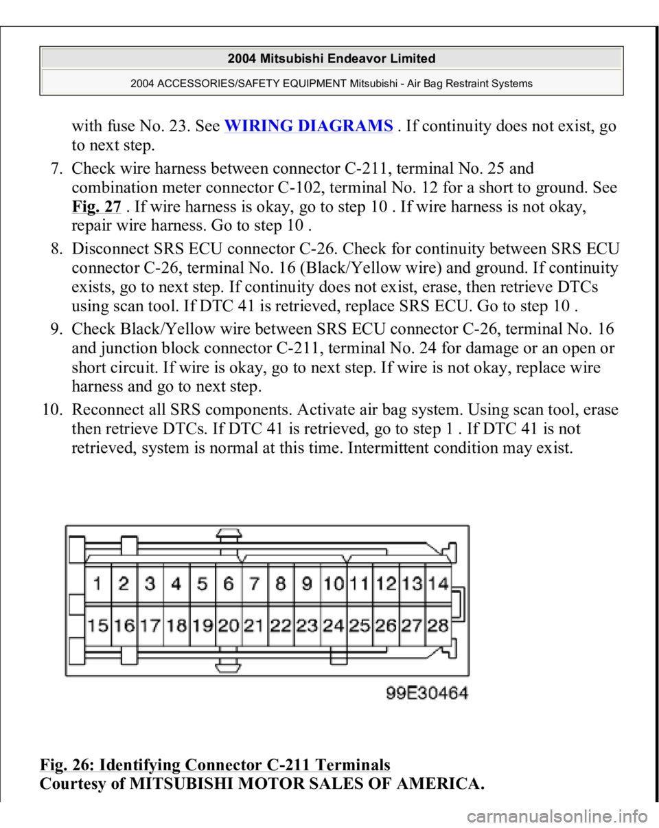
Fig. 26: Identifying Connector C
-211 Terminals
Courtesy of MITSUBISHI MOTOR SALES OF AMERICA.
2004 Mitsubishi Endeavor Limited
2004 ACCESSORIES/SAFETY EQUIPMENT Mitsubishi - Air Bag Restraint Systems
Page 346 of 3870
then retrieve DTCs. If DTC 94 is retrieved, go to step 1 . If DTC 94 is not
retrieved, system is normal at this time. Intermittent condition may exist.
DIAGNOSTIC TESTS (DUAL-STAGE AIR BAG SYSTEM) INSPECTION PROCEDURE 1 Connect scan tool to Data Link Connector (DLC). See INITIAL SRS DIAGNOSTIC PROCEDURE
under DIAGNOSTICS. Turn ignition on. If scan
tool is able to diagnose CAN bus lines and CAN bus lines are satisfactory, inspect
and repair power circuits. Go to INSPECTION PROCEDURE 2
. If scan tool
cannot diagnose CAN bus lines, inspect and repair CAN bus lines.
INSPECTION PROCEDURE 2 1. Connect scan tool to Data Link Connector (DLC). See INITIAL SRS
DIAGNOSTIC PROCEDURE
under DIAGNOSTICS. Disconnect SRS ECU
connector C-26. See SRS ELECTRONIC CONTROL UNIT (SRS ECU)
under REMOVAL & INSTALLATION. See Fig. 30
. Measure resistance
between ground and connector C-26, terminal No. 40 (Black wire). If
resistance is 2 ohms or less, go to next step. If resistance is more than 2 ohms,
repair wiring harness between SRS ECU and ground. See WIRE REPAIR
.
2. Inspect Black/White wire and Black/Yellow wire between connector C-26 and
ignition switch connector C-308, including junction block connectors C-211
and C-215. See Fig. 22
. If wires are okay, go to next step. If wires are not
okay, replace wire harness.
3. Inspect battery. If battery is in good condition, go to next step. If battery is not
in good condition, charge or replace battery as appropriate. Go to step 5 .
4. Inspect charging system. If charging system is okay, go to next step. If
charging system is not okay, repair charging system as appropriate. Go to next
step.
5. Retest SRS system. If scan tool can communicate with SRS ECU, an
intermittent condition may have existed. If scan tool cannot communicate with
NOTE: If scan tool cannot communicate with SRS ECU, CAN bus
line may be defective.
2004 Mitsubishi Endeavor Limited
2004 ACCESSORIES/SAFETY EQUIPMENT Mitsubishi - Air Bag Restraint Systems
Page 396 of 3870
next step. If DTC B1477 is not retrieved, an intermittent condition may exist.
3. Remove fuse No. 23 from instrument panel junction block. See Fig. 39
. If fuse
is blown, go to step 6 . If fuse is not blown, go to next step.
4. Disconnect negative battery cable. Disconnect SRS ECU connector C-26. See
SRS ELECTRONIC CONTROL UNIT (SRS ECU)
under REMOVAL &
INSTALLATION. See Fig. 30
. Connect negative battery cable. Turn ignition
on. Measure voltage between ground and SRS ECU connector C-26, terminal
No. 24 (Black/Yellow wire). If voltage is 9 volts or more, reconnect SRS
components. Erase, then retrieve DTCs. If DTC B1477 is retrieved, replace
SRS ECU. Go to step 8 . If DTC B1477 is not retrieved, go to next step.
5. Inspect Black/Yellow wire between SRS ECU connector C-26, terminal No. 24
and ignition switch connector C-308, terminal No. 2. See WIRING
DIAGRAMS
. If wire is okay, go to step 8 . If wire is not okay, replace
harness between SRS ECU and ignition switch. Go to step 8 .
6. Replace fuse. Turn ignition on for one minute, then turn off. Inspect fuse. If
fuse is okay, go to step 8 . If fuse is not okay, go to next step.
7. Measure resistance between SRS ECU connector terminal No. 24 and ground.
If zero ohms is measured, inspect all circuits running from fuse No. 23 for a
short to ground. including connector C-211. See Fig. 22
. Repair short to
ground. See WIRE REPAIR
. Go to next step. If continuity does not exist,
reconnect SRS components. Erase, then retrieve DTCs. If DTC B1477 is
retrieved, replace SRS ECU. Go to next step.
8. Reconnect all SRS components. Activate air bag system. Using scan tool,
retrieve DTCs. If DTC B1473 is retrieved, go to step 1 . If DTC B1473 is not
retrieved, system is normal at this time.
DTC B1478: SRS ECU CAPACITOR CIRCUIT VOLTAGE HIGH 1. Connect scan tool to Data Link Connector (DLC). See INITIAL SRS
DIAGNOSTIC PROCEDURE
under DIAGNOSTICS. If scan tool is able to
diagnose CAN bus lines and CAN bus lines are satisfactory, go to next step. If
scan tool cannot diagnose CAN bus lines, repair CAN bus lines. Go to next
step.
2. Erase, then retrieve DTCs. If DTC B1478 is retrieved, replace SRS ECU. See
SRS ELECTRONIC CONTROL UNIT (SRS ECU)
under REMOVAL &
2004 Mitsubishi Endeavor Limited
2004 ACCESSORIES/SAFETY EQUIPMENT Mitsubishi - Air Bag Restraint Systems
Page 445 of 3870
6 . If ACCURACY CHECK COMPLETION is not displayed, go to next step.
5. If ABNORMAL CONDITION is displayed, press OK and go to calibration
screen. Remove weight from seat. Verify seat is installed correctly. If seat is
installed correctly, go to step 1 .
6. Remove weight from seat cushion. Move seat to rear most position. Repeat
step2 . Go to next step.
7. Select INTERACTIVE DIAGNOSIS, then SPECIAL FUNCTION then SEAT
WEIGHT SENSOR ACCURACY CHECK on screen. Place a 66 pound weight
(30 kg) in center of passenger-side seat cushion. Repeat step2 . Touch OK
button to perform accuracy check. Go to next step.
8. If variance between sensor output and input levels is within 11 pounds (5 kg),
ACCURACY CHECK COMPLETION will be displayed on screen.
Calibration is complete. If ACCURACY CHECK COMPLETION is not
displayed, go to next step.
9. Verify seat is installed correctly. Repeat step2 . Touch OK button. When
EXECUTION prompt is displayed, touch OK button. When calibration is
completed, screen will display ZERO CALIBRATION COMPLETED. If
calibration cannot be completed, an intermittent condition may exist.
FRONT IMPACT SENSOR (DUAL-STAGE AIR BAG SYSTEM) 1. Remove appropriate front impact sensor. See FRONT IMPACT SENSOR
under REMOVAL & INSTALLATION. Visually inspect front impact sensor
case, connectors and brackets for damage. If no damage is found, go to next
step. If damage is found, discard front impact sensor.
2. Measure resistance between terminals of front impact sensor. Resistance
should be 738-902 ohms. Measure resistance between front impact sensor
terminals and front impact sensor case. Resistance should be infinite. If
resistance is not as specified, replace front impact sensor.
WIRING DIAGRAMS
2004 Mitsubishi Endeavor Limited
2004 ACCESSORIES/SAFETY EQUIPMENT Mitsubishi - Air Bag Restraint Systems
Page 799 of 3870
Technical Descriptio
n
The cause could be a malfunction of the fan control module power supply or
ground circuit. The cause could also be a malfunction of the fan control module or the PCM.
Troubleshooting Hints
Malfunction of fusible link. Malfunction of fan control relay. Malfunction of MFI relay. Malfunction of radiator fan motor. Malfunction of condenser fan motor. Malfunction of fan control module. Malfunction of PCM. Damaged wiring harness or connector.
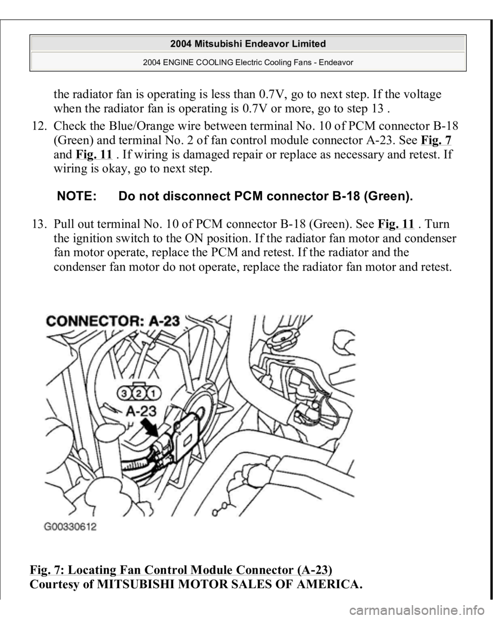
Diagnosis 1. Disconnect fan control module connector A-23. See Fig. 7
. Measure for
voltage between terminal No. 3 (harness side of the connector) and ground
when ignition switch is turned to the ON position. If battery voltage is not
achieved, go to next step. If battery voltage is achieved, go to step 8 .
2. Check fan control relay. See FAN CONTROL RELAY under
COMPONENTS TESTS. If fan control relay is okay, go to next step. If fan
control relay is not okay, replace it and retest.
3. Check the MFI relay. See MULTI
-PORT FUEL INJECTION (MFI)
RELAY
under COMPONENT TESTS. If MFI relay is okay, go to next step. If
MFI relay is not okay, replace it and retest.
4. Check for harness damage in Black/Yellow wire between fusible link No. 2
and terminal No. 4 of fan control relay connector A-10X. See Fig. 8
. If wire is
okay, go to next step. If wire is damaged, repair or replace as necessary and
retest.
5. Check for harness damage in Blue wire between terminal No. 2 of fan control
rela
y connector
A-10X and terminal No. 3 of fan control module connector A-
2004 Mitsubishi Endeavor Limited
2004 ENGINE COOLING Electric Cooling Fans - Endeavor
Page 801 of 3870
the radiator fan is operating is less than 0.7V, go to next step. If the voltage
when the radiator fan is operating is 0.7V or more, go to step 13 .
12. Check the Blue/Orange wire between terminal No. 10 of PCM connector B-18
(Green) and terminal No. 2 of fan control module connector A-23. See Fig. 7
and Fig. 11
. If wiring is damaged repair or replace as necessary and retest. If
wiring is okay, go to next step.
13. Pull out terminal No. 10 of PCM connector B-18 (Green). See Fig. 11
. Turn
the ignition switch to the ON position. If the radiator fan motor and condenser
fan motor operate, replace the PCM and retest. If the radiator and the
condenser fan motor do not operate, replace the radiator fan motor and retest.
Fig. 7: Locating Fan Control Module Connector (A
-23)
Courtesy of MITSUBISHI MOTOR SALES OF AMERICA.
NOTE: Do not disconnect PCM connector B-18 (Green).
2004 Mitsubishi Endeavor Limited
2004 ENGINE COOLING Electric Cooling Fans - Endeavor
Page 807 of 3870
Fig. 12: Identifying Power Plant ECU Check Harness (MB991923)
Courtesy of MITSUBISHI MOTOR SALES OF AMERICA.
TEST B: RADIATOR FAN & CONDENSER FAN DO NOT CHANGE SPEED OR STOP Technical Description The fan control module has variable control of the radiator fan motor and the
condenser fan motor speeds using signals transmitted from the PCM. Troubleshooting Hints
Malfunction of fan control relay. Malfunction of fan control module. Malfunction of PCM.
Diagnosis 1. Check the fan control relay. See FAN CONTROL RELAY
under
COMPONENT TESTS. If fan control relay is okay, go to next step. If fan
control module is damaged, repair or replace as necessary and retest.
2. Check the harness wire between terminal No. 2 of fan control relay connector
A-10X and terminal No. 3 of fan control module connector A-18. See Fig. 7
and Fig. 8
. If wiring is damaged, repair or replace as necessary and retest. If
wiring is okay, go to next step.
3. Disconnect all the connectors from the PCM. Connect Power Plant ECU Check
Harness (MB991923
) between the PCM and the bod
y-side harness connector.
NOTE: If the engine coolant temperature reaches 230°F (110°C) or
higher, the radiator fan control runs the radiator fan for up
to 5 minutes even after the ignition switch is turned to the
LOCK position. The fan stops its rotation when the engine
coolant temperature decreases to 230°F (110°C) or l ower.
NOTE: Measure the output circuit voltage at terminal No. 10 of
PCM connector B-18 by using Power Plant ECU Check
Harness (MB991923). See Fig. 11
and Fig. 12
.
2004 Mitsubishi Endeavor Limited
2004 ENGINE COOLING Electric Cooling Fans - Endeavor
Page 808 of 3870
See Fig. 12
. Start the engine and allow it to idle. Measure the voltage between
terminal No. 10 of connector B-18 and ground. See Fig. 12
. If the voltage
when the radiator fan is not operating is more than 0.3V, go to next step. If the
voltage when the radiator fan is not operating is less than 0.3V, retest.
4. Check fan control module connector A-23 and PCM connector B-18 for loose,
corroded, or damaged terminals, or terminals pushed back in the connector.
See Fig. 7
and Fig. 11
. If connectors are okay, go to next step. If connectors
are damaged, repair or replace as necessary and retest.
5. Check the harness wire between terminal No. 10 of PCM connector B-18
(Green) and terminal No. 2 of fan control module connector A-23. See Fig. 7
and Fig. 11
. If wiring is damaged repair or replace as necessary and retest. If
wiring is okay, go to next step.
6. Disconnect PCM connector B-18 (Green). See Fig. 11
. Pull out pin No. 10 and
connect it to a body ground. Reconnect PCM connector with pin No. 10 still
removed. Turn the ignition switch to ON position. If the radiator fan motor and
condenser fan motor fan motor stop operating, replace the PCM and retest. If
the radiator fan motor and condenser fan motor do not stop operating, replace
the fan control module and retest.
TEST C: RADIATOR FAN DOES NOT OPERATE Technical Description The cause could be a malfunction of the radiator fan motor or an open circuit
between the fan control module and the radiator fan. Troubleshooting Hints
Malfunction of radiator fan motor.
Diagnosis If radiator fan does not operate, replace the radiator fan.
NOTE: Check terminal No. 7 of intermediate connector A-13,
repair it and then check wiring. See Fig. 9
.
2004 Mitsubishi Endeavor Limited
2004 ENGINE COOLING Electric Cooling Fans - Endeavor