Page 191 of 3870

Courtesy of MITSUBISHI MOTOR SALES OF AMERICA
.
6. Turn the ignition switch to the "LOCK" (OFF) position.
Q: Is DTC C1860 or C1861 set?
YES: Go to Step 3.
NO: The procedure is complete.
STEP 3. Check the battery.
Check the battery (Refer to BATTERY TEST
).
Q: Is the battery in good condition?
YES: Go to Step 4.
NO: Charge or replace the battery.
STEP 4. Check the charging system.
Check the charging system (Refer to GENERATORS & REGULATORS
).
Q: Is the charging system in good condition?
YES: Go to Step 5.
NO: Repair or replace the charging system component(s).
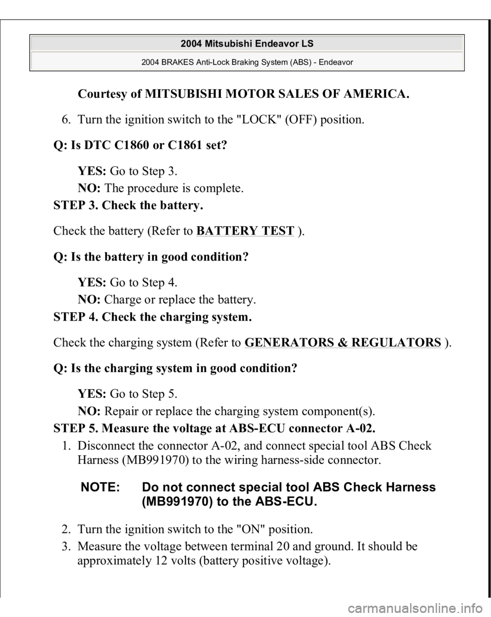
STEP 5. Measure the voltage at ABS-ECU connector A-02.
1. Disconnect the connector A-02, and connect special tool ABS Check
Harness (MB991970) to the wiring harness-side connector.
2. Turn the ignition switch to the "ON" position.
3. Measure the voltage between terminal 20 and ground. It should be
approximately 12 volts (battery positive voltage). NOTE: Do not connect special tool ABS Check Harness
(MB991970) to the ABS-ECU.
2004 Mitsubishi Endeavor LS
2004 BRAKES Anti-Lock Braking System (ABS) - Endeavor
Page 197 of 3870
Fig. 115: Checking Ignition Switch Connector C
-308
Courtesy of MITSUBISHI MOTOR SALES OF AMERICA.
Check the connectors, for loose, corroded or damaged terminals, or terminals
pushed back in the connector.
Q: Are the connectors and terminals in good condition?
YES: An open or short circuit may be present in the power supply line to
the ABS-ECU. Repair the wiring harness between ABS-ECU connector
A-02 terminal 20 and ignition switch connector C-308 terminal 4. Then go
to Ste
p 8 .
2004 Mitsubishi Endeavor LS
2004 BRAKES Anti-Lock Braking System (ABS) - Endeavor
Page 202 of 3870

Courtesy of MITSUBISHI MOTOR SALES OF AMERICA
.
6. Turn the ignition switch to the "LOCK" (OFF) position.
Q: Is DTC C1860 or C1861 set?
YES: Go to Step 1 .
NO: The procedure is complete.
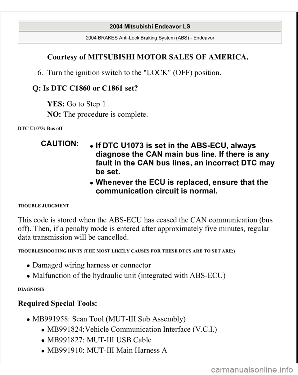
DTC U1073: Bus off TROUBLE JUDGMENT This code is stored when the ABS-ECU has ceased the CAN communication (bus
off). Then, if a penalty mode is entered after approximately five minutes, regular
data transmission will be cancelled. TROUBLESHOOTING HINTS (THE MOST LIKELY CAUSES FOR THESE DTCS ARE TO SET ARE:)
Damaged wiring harness or connector Malfunction of the hydraulic unit (integrated with ABS-ECU)
DIAGNOSIS Required Special Tools:
MB991958: Scan Tool (MUT-III Sub Assembly)
MB991824:Vehicle Communication Interface (V.C.I.) MB991827: MUT-III USB Cable MB991910: MUT-III Main Harness A CAUTION:
If DTC U1073 is set in the ABS-ECU, always
diagnose the CAN main bus line. If there is any
fault in the CAN bus lines, an incorrect DTC may
be set. Whenever the ECU is replaced, ensure that the
communication circuit is normal.
2004 Mitsubishi Endeavor LS
2004 BRAKES Anti-Lock Braking System (ABS) - Endeavor
Page 212 of 3870
Fig. 123: Identifying Connectors: C
-121, C
-214, C
-215
Courtesy of MITSUBISHI MOTOR SALES OF AMERICA.
TECHNICAL DESCRIPTION (COMMENT) If the scan tool (MUT-III Sub Assembly) can not communicate with the ABS
system, the CAN bus lines may be defective. If the ABS system does not work, the
ABS-ECU or its power supply circuit may be defective. TROUBLESHOOTING HINTS (THE MOST LIKELY CAUSES FOR THIS CASE:)
Damaged wiring harness or connector Malfunction of the hydraulic unit (Integrated with ABS-ECU)
DIAGNOSIS Required Special Tools:
MB991958: Scan Tool (MUT-III Sub Assembly)
MB991824: Vehicle Communication Interface (V.C.I.) MB991827: MUT-III USB Cable MB991910: MUT-III Main Harness A
STEP 1. Using scan tool MB991958, diagnose the CAN bus line.
CAUTION: To prevent damage to scan tool MB991958,
always turn the ignition switch to the
"LOCK" (OFF) position before connecting or
2004 Mitsubishi Endeavor LS
2004 BRAKES Anti-Lock Braking System (ABS) - Endeavor
Page 217 of 3870
Fig. 126: Identifying Connectors: C
-214, C
-215
Courtesy of MITSUBISHI MOTOR SALES OF AMERICA.
CIRCUIT OPERATION
The ABS-ECU is energized by the ignition switch (IG2) through multi-purpose
fuse 13 and the ABS-ECU terminal 20. If the power supply to the ABS-ECU has failed, scan tool (MUT-III Sub
Assembly) will not be able to communicate with it.
TROUBLESHOOTING HINTS (THE MOST LIKELY CAUSES FOR THIS CASE:)
Damaged wiring harness or connector Defective battery Charging system failed Malfunction of the hydraulic unit (integrated with ABS-ECU)
DIAGNOSIS
2004 Mitsubishi Endeavor LS
2004 BRAKES Anti-Lock Braking System (ABS) - Endeavor
Page 218 of 3870
Required Special Tools:
MB991958: Scan Tool (MUT-III Sub Assembly)
MB991824: Vehicle Communication Interface (V.C.I.) MB991827: MUT-III USB Cable MB991910: MUT-III Main Harness A
MB991970: ABS Check Harness
STEP 1. Measure the voltage at ABS-ECU connector A-02.
1. Disconnect the connector A-02, and connect special tool ABS Check
Harness (MB991970) to the wiring harness-side connector.
2. Turn the ignition switch to the "ON" position.
3. Measure the voltage between terminal 20 and ground. It should measure
approximately 12 volts (battery positive voltage). NOTE: Do not connect special tool ABS Check Harness
(MB991970) to the ABS-ECU.
2004 Mitsubishi Endeavor LS
2004 BRAKES Anti-Lock Braking System (ABS) - Endeavor
Page 224 of 3870
Fig. 131: Checking Ignition Switch Connector C
-308
Courtesy of MITSUBISHI MOTOR SALES OF AMERICA.
Check the connectors, for loose, corroded or damaged terminals, or terminals
pushed back in the connector.
Q: Are the connectors and terminals in good condition?
YES: An open or short circuit may be present in the power supply line to
the ABS-ECU. Repair the wiring harness between ABS-ECU connector
A-02 terminal 20 and ignition switch connector C-308 terminal 4. Then go
to Ste
p 8 .
2004 Mitsubishi Endeavor LS
2004 BRAKES Anti-Lock Braking System (ABS) - Endeavor
Page 225 of 3870
NO: Repair or replace the damaged component(s). Then go to Step 8 .
STEP 3. Measure the resistance at ABS-ECU connector A-02.
1. Disconnect the connector A-02, and connect special tool ABS Check
Harness (MB991970) to the wiring harness-side connector.
2. Measure the resistance between terminal 2, 18 and ground.
It should be 2 ohms or less.NOTE: Do not connect special tool ABS Check Harness
(MB991970) to the ABS-ECU.
2004 Mitsubishi Endeavor LS
2004 BRAKES Anti-Lock Braking System (ABS) - Endeavor