Page 2840 of 4264
6E–264 ENGINE DRIVEABILITY AND EMISSIONS
ON-VEHICLE SERVICE PROCEDURE
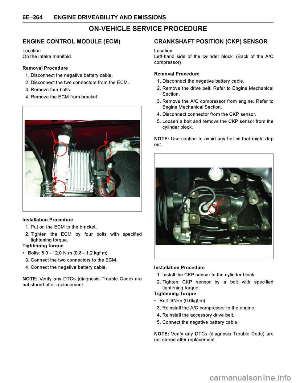
ENGINE CONTROL MODULE (ECM)
Location
On the intake manifold.
Removal Procedure
1. Disconnect the negative battery cable.
2. Disconnect the two connectors from the ECM.
3. Remove four bolts.
4. Remove the ECM from bracket.
Installation Procedure
1. Put on the ECM to the bracket.
2. Tighten the ECM by four bolts with specified
tightening torque.
Tightening torque
Bolts: 8.0 - 12.0 N·m (0.8 - 1.2 kgf·m)
3. Connect the two connectors to the ECM.
4. Connect the negative battery cable.
NOTE: Verify any DTCs (diagnosis Trouble Code) are
not stored after replacement.
CRANKSHAFT POSITION (CKP) SENSOR
Location
Left-hand side of the cylinder block. (Back of the A/C
compressor)
Removal Procedure
1. Disconnect the negative battery cable.
2. Remove the drive belt. Refer to Engine Mechanical
Section.
3. Remove the A/C compressor from engine. Refer to
Engine Mechanical Section.
4. Disconnect connector from the CKP sensor.
5. Loosen a bolt and remove the CKP sensor from the
cylinder block.
NOTE: Use caution to avoid any hot oil that might drip
out.
Installation Procedure
1. Install the CKP sensor to the cylinder block.
2. Tighten CKP sensor by a bolt with specified
tightening torque.
Tightening Torque
Bolt: 6N·m (0.6kgf·m)
3. Reinstall the A/C compressor to the engine.
4. Reinstall the accessory drive belt.
5. Connect the negative battery cable.
NOTE: Verify any DTCs (diagnosis Trouble Code) are
not stored after replacement.
Page 2841 of 4264
ENGINE DRIVEABILITY AND EMISSIONS 6E–265
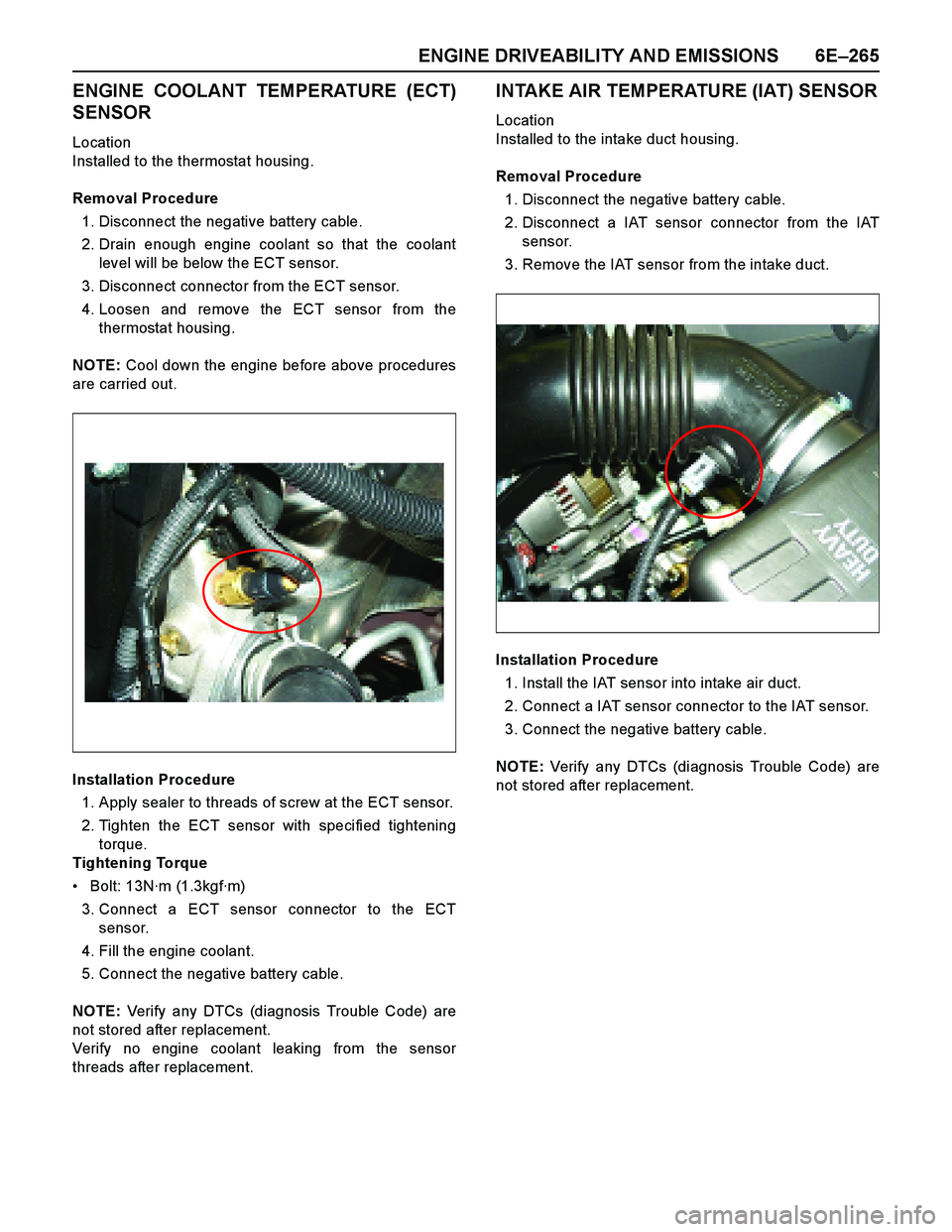
ENGINE COOLANT TEMPERATURE (ECT)
SENSOR
Location
Installed to the thermostat housing.
Removal Procedure
1. Disconnect the negative battery cable.
2. Drain enough engine coolant so that the coolant
level will be below the ECT sensor.
3. Disconnect connector from the ECT sensor.
4. Loosen and remove the ECT sensor from the
thermostat housing.
NOTE: Cool down the engine before above procedures
are carried out.
Installation Procedure
1. Apply sealer to threads of screw at the ECT sensor.
2. Tighten the ECT sensor with specified tightening
torque.
Tightening Torque
Bolt: 13N·m (1.3kgf·m)
3. Connect a ECT sensor connector to the ECT
sensor.
4. Fill the engine coolant.
5. Connect the negative battery cable.
NOTE: Verify any DTCs (diagnosis Trouble Code) are
not stored after replacement.
Verify no engine coolant leaking from the sensor
threads after replacement.
INTAKE AIR TEMPERATURE (IAT) SENSOR
Location
Installed to the intake duct housing.
Removal Procedure
1. Disconnect the negative battery cable.
2. Disconnect a IAT sensor connector from the IAT
sensor.
3. Remove the IAT sensor from the intake duct.
Installation Procedure
1. Install the IAT sensor into intake air duct.
2. Connect a IAT sensor connector to the IAT sensor.
3. Connect the negative battery cable.
NOTE: Verify any DTCs (diagnosis Trouble Code) are
not stored after replacement.
Page 2842 of 4264
6E–266 ENGINE DRIVEABILITY AND EMISSIONS
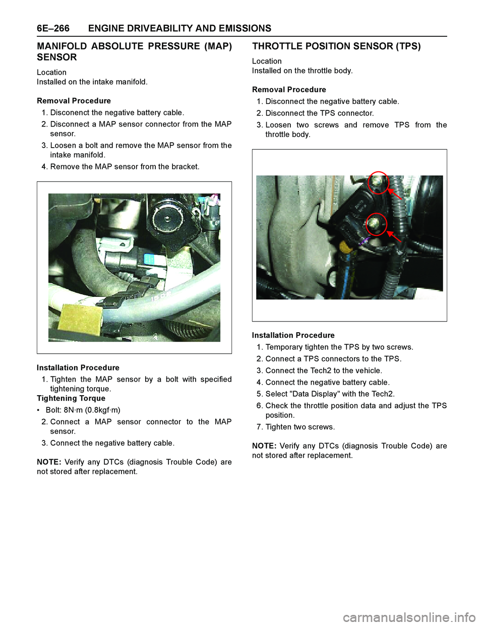
MANIFOLD ABSOLUTE PRESSURE (MAP)
SENSOR
Location
Installed on the intake manifold.
Removal Procedure
1. Disconenct the negative battery cable.
2. Disconnect a MAP sensor connector from the MAP
sensor.
3. Loosen a bolt and remove the MAP sensor from the
intake manifold.
4. Remove the MAP sensor from the bracket.
Installation Procedure
1. Tighten the MAP sensor by a bolt with specified
tightening torque.
Tightening Torque
Bolt: 8N·m (0.8kgf·m)
2. Connect a MAP sensor connector to the MAP
sensor.
3. Connect the negative battery cable.
NOTE: Verify any DTCs (diagnosis Trouble Code) are
not stored after replacement.
THROTTLE POSITION SENSOR (TPS)
Location
Installed on the throttle body.
Removal Procedure
1. Disconnect the negative battery cable.
2. Disconnect the TPS connector.
3. Loosen two screws and remove TPS from the
throttle body.
Installation Procedure
1. Temporary tighten the TPS by two screws.
2. Connect a TPS connectors to the TPS.
3. Connect the Tech2 to the vehicle.
4. Connect the negative battery cable.
5. Select "Data Display" with the Tech2.
6. Check the throttle position data and adjust the TPS
position.
7. Tighten two screws.
NOTE: Verify any DTCs (diagnosis Trouble Code) are
not stored after replacement.
Page 2843 of 4264
ENGINE DRIVEABILITY AND EMISSIONS 6E–267
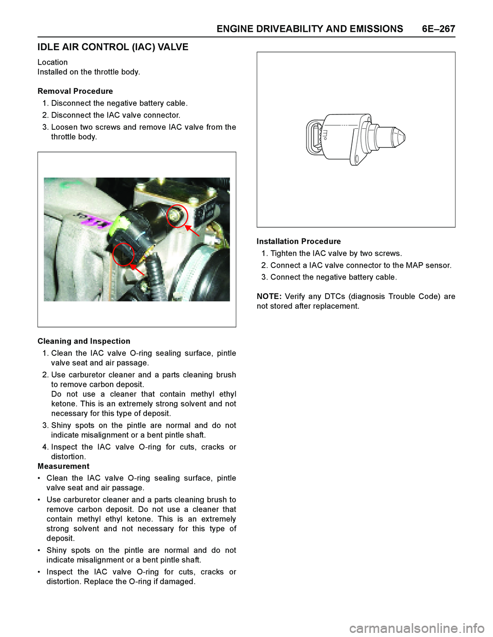
IDLE AIR CONTROL (IAC) VALVE
Location
Installed on the throttle body.
Removal Procedure
1. Disconnect the negative battery cable.
2. Disconnect the IAC valve connector.
3. Loosen two screws and remove IAC valve from the
throttle body.
Cleaning and Inspection
1. Clean the IAC valve O-ring sealing surface, pintle
valve seat and air passage.
2. Use carburetor cleaner and a parts cleaning brush
to remove carbon deposit.
Do not use a cleaner that contain methyl ethyl
ketone. This is an extremely strong solvent and not
necessary for this type of deposit.
3. Shiny spots on the pintle are normal and do not
indicate misalignment or a bent pintle shaft.
4. Inspect the IAC valve O-ring for cuts, cracks or
distortion.
Measurement
Clean the IAC valve O-ring sealing surface, pintle
valve seat and air passage.
Use carburetor cleaner and a parts cleaning brush to
remove carbon deposit. Do not use a cleaner that
contain methyl ethyl ketone. This is an ex tremely
strong solvent and not necessary for this type of
deposit.
Shiny spots on the pintle are normal and do not
indicate misalignment or a bent pintle shaft.
Inspect the IAC valve O-ring for cuts, cracks or
distortion. Replace the O-ring if damaged.Installation Procedure
1. Tighten the IAC valve by two screws.
2. Connect a IAC valve connector to the MAP sensor.
3. Connect the negative battery cable.
NOTE: Verify any DTCs (diagnosis Trouble Code) are
not stored after replacement.
Page 2844 of 4264
6E–268 ENGINE DRIVEABILITY AND EMISSIONS
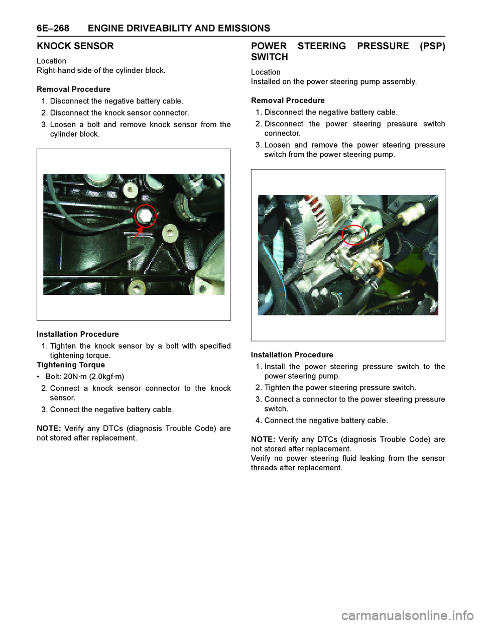
KNOCK SENSOR
Location
Right-hand side of the cylinder block.
Removal Procedure
1. Disconnect the negative battery cable.
2. Disconnect the knock sensor connector.
3. Loosen a bolt and remove knock sensor from the
cylinder block.
Installation Procedure
1. Tighten the knock sensor by a bolt with specified
tightening torque.
Tightening Torque
Bolt: 20N·m (2.0kgf·m)
2. Connect a knock sensor connector to the knock
sensor.
3. Connect the negative battery cable.
NOTE: Verify any DTCs (diagnosis Trouble Code) are
not stored after replacement.
POWER STEERING PRESSURE (PSP)
SWITCH
Location
Installed on the power steering pump assembly.
Removal Procedure
1. Disconnect the negative battery cable.
2. Disconnect the power steering pressure switch
connector.
3. Loosen and remove the power steering pressure
switch from the power steering pump.
Installation Procedure
1. Install the power steering pressure switch to the
power steering pump.
2. Tighten the power steering pressure switch.
3. Connect a connector to the power steering pressure
switch.
4. Connect the negative battery cable.
NOTE: Verify any DTCs (diagnosis Trouble Code) are
not stored after replacement.
Verify no power steering fluid leaking from the sensor
threads after replacement.
Page 2845 of 4264
ENGINE DRIVEABILITY AND EMISSIONS 6E–269
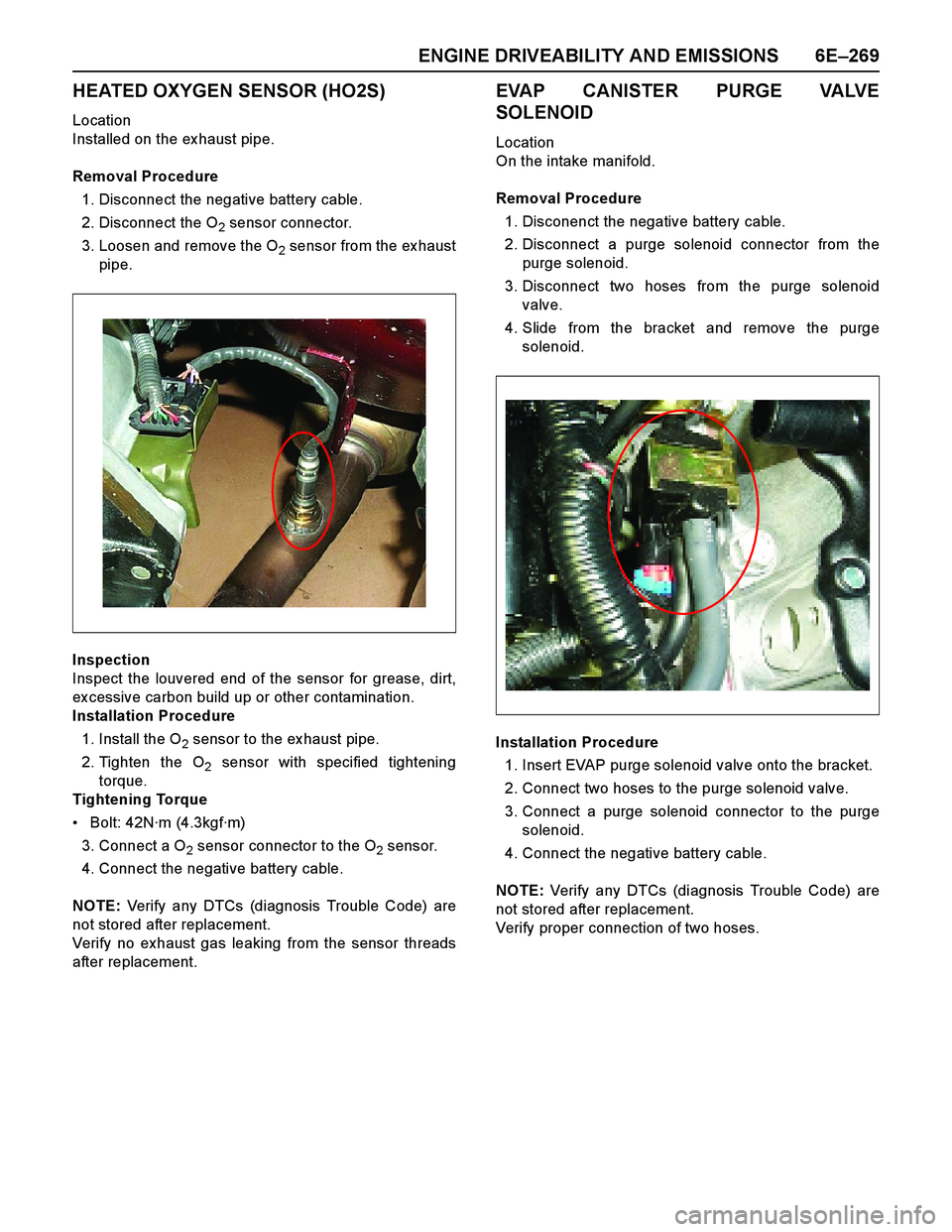
HEATED OXYGEN SENSOR (HO2S)
Location
Installed on the ex haust pipe.
Removal Procedure
1. Disconnect the negative battery cable.
2. Disconnect the O
2 sensor connector.
3. Loosen and remove the O
2 sensor from the ex haust
pipe.
Inspection
Inspect the louvered end of the sensor for grease, dirt,
ex cessive carbon build up or other contamination.
Installation Procedure
1. Install the O
2 sensor to the ex haust pipe.
2. Tighten the O
2 sensor with specified tightening
torque.
Tightening Torque
Bolt: 42N·m (4.3kgf·m)
3. Connect a O
2 sensor connector to the O2 sensor.
4. Connect the negative battery cable.
NOTE: Verify any DTCs (diagnosis Trouble Code) are
not stored after replacement.
Verify no exhaust gas leaking from the sensor threads
after replacement.
EVAP CANISTER PURGE VALVE
SOLENOID
Location
On the intake manifold.
Removal Procedure
1. Disconenct the negative battery cable.
2. Disconnect a purge solenoid connector from the
purge solenoid.
3. Disconnect two hoses from the purge solenoid
valve.
4. Slide from the bracket and remove the purge
solenoid.
Installation Procedure
1. Insert EVAP purge solenoid valve onto the bracket.
2. Connect two hoses to the purge solenoid valve.
3. Connect a purge solenoid connector to the purge
solenoid.
4. Connect the negative battery cable.
NOTE: Verify any DTCs (diagnosis Trouble Code) are
not stored after replacement.
Verify proper connection of two hoses.
Page 2865 of 4264
ENGINE EXHAUST 6F-9
Catalytic Converter (If applicable)
Catalytic Converter and Associated Parts
RTW46FSF000301
Legend
1. Catalytic Converter
2. O
2 Sensor Converter
3. Front Pipe Fixing Nuts
4. Mid Pipe Fixing Nuts
Removal
(2.4L)
1. Disconnect battery ground cable.
2. Raise the vehicle and support with suitable safety stands.
3. Remove front pipe fixing nuts (3).
4. Remove mid pipe fixing nuts (4).
5. Remove the O
2 sensor connector (2).
6. Remove the front exhaust pipe with catalytic converter (1).
Installation
1. Install Catalytic Converter (1) and tighten four to the
specified torque:
Torque:
Fixing nuts: 28 N�
�� �m (2.9 kgf�
�� �m)
2. Tight two nuts (4)
Torque:
Nuts: 43 N�
�� �m (4.4 kgf�
�� �m)
3. Connect the O
2 sensor connector (2).
Page 2886 of 4264
6J-2 INDUCTION
Service Precaution
CAUTION:
Always use the correct fastener in the proper location.
When you replace a fastener, use ONLY the exact part
number for that application. ISUZU will call out those
fasteners that require a replacement after removal. ISUZU
will also call out the fasteners that require thread lockers
or thread sealant. UNLESS OTHERWISE SPECIFIED, do
not use supplemental coatings (Paints, greases, or other
corrosion inhibitors) on threaded fasteners or fastener
joint interfaces. Generally, such coatings adversely affect
the fastener torque and the joint clamping force, and may
damage the fastener. When you install fasteners, use the
correct tightening sequence and specifications. Following
these instructions can help you avoid damage to parts
and systems.
RTW46JSH000101
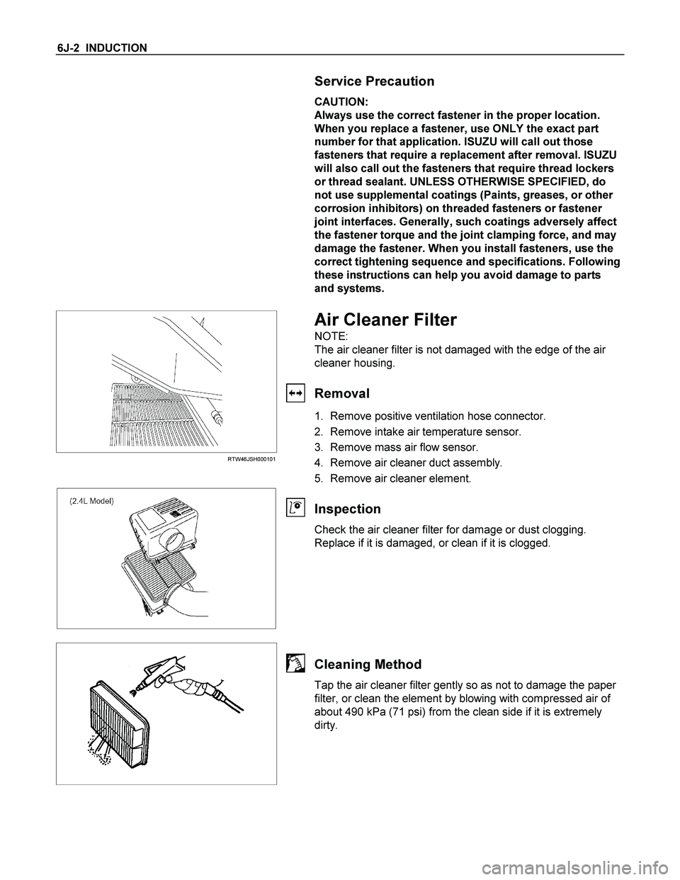
Air Cleaner Filter
NOTE:
The air cleaner filter is not damaged with the edge of the air
cleaner housing.
Removal
1. Remove positive ventilation hose connector.
2. Remove intake air temperature sensor.
3. Remove mass air flow sensor.
4. Remove air cleaner duct assembly.
5. Remove air cleaner element.
Inspection
Check the air cleaner filter for damage or dust clogging.
Replace if it is damaged, or clean if it is clogged.
Cleaning Method
Tap the air cleaner filter gently so as not to damage the paper
filter, or clean the element by blowing with compressed air of
about 490 kPa (71 psi) from the clean side if it is extremely
dirty.