Page 3230 of 4264
7B1-66 MANUAL TRANSMISSION
6. Remove gear control lever (5).
7. Raise and support vehicle with suitable stands.
8. Remove rear propeller shaft (6).
NOTE: Apply alignment marks on the flange at the
differential side.
9. Remove front propeller shaft (7).
NOTE: Apply alignment marks on the flange at both
front and rear sides.
401RS023
10. Loosen the front exhaust pipe fixing nuts (8) at the
engine side but not remove them. (Diesel engine
only)
150R300004
11. Remove the exhaust pipe (9). (6VE1 only)
RTW37ASH000101
12. Disconnect harness connectors and clips on the
transfer.
�
Actuator connector
�
Car Speed Sensor
810R300069
Legend
(1) Neutral Switch Connector: Transmission
(2) Back up Switch Connector
(3) Speed Sensor Connector
(4) Actuator Connector
(5) 2W - 4W Switch Connector
(6) Neutral Switch Connector: Transfer
Page 3237 of 4264
.(Diesel engine)
NOTE: Tighten the lower bolt temporarily.
After installing the fuel pipe assembly, tighten the bolt to
the specified torque")
MANUAL TRANSMISSION 7B1-73
6. Install starter(16).(Diesel engine)
NOTE: Tighten the lower bolt temporarily.
After installing the fuel pipe assembly, tighten the bolt to
the specified torque.
Torque: 76 N�
�� �m (7.7 kg�
�� �m/56 lb�
�� �ft)
7. Install the rear support rubber on the transmission
and tighten the bolts to the specified torque.
Torque: 50 N�
�� �m (5.1 kg�
�� �m/37 lb�
�� �ft)
8. Install the middle part of transmission crossmember
(15) and bolts.
Tighten the nuts to the specified torque.
Torque: 67 N�
�� �m (6.8 kg�
�� �m/49 lb�
�� �ft)
9. Install engine rear mount nuts (14).
Torque: 52 N�
�� �m (5.3 kg�
�� �m/38 lb�
�� �ft)
Remove the transmission jack from transmission
side.
10. Apply grease to top hole portion of the shift fork.
Install slave cylinder (13) and tighten the bolts to the
specified torque.
Torque: 76 N�
�� �m (7.7 kg�
�� �m/56 lb�
�� �ft)
11. Install the fuel pipe brackets on the transmission.
Install the fuel pipe assembly to the fuel pipe
brackets
Torque: Bolt & Nut 76 N�
�� �m (7.7 kg�
�� �m/56 lb�
�� �ft)
Nut 37 N�
�� �m (3.8 kg�
�� �m/28 lb�
�� �ft)
Diesel engine
220R300012
Legend
(1) Bolt
(2) Nut
(3) Fuel Pipe Assembly
6VE1, C24NE
Scan-2
12. Connect transmission harness connectors and clips.
Connector: transfer neutral switch, 2W - 4W switch,
backup switch, transmission neutral switch.
810R300069
Legend
(1) Neutral Switch Connector: Transmission
(2) Backup Switch Connector
(3) Speed Sensor Connector
(4) Actuator Connector
(5) 2W - 4W Switch connector
(6) Neutral Switch Connector: Transfer
13. Apply grease (BESCO L2 or equivalent) on the
splined portion of the output shaft.
14. Connect the transfer to the transmission.
Page 3298 of 4264
11A-12 IMMOBILIZER SYSTEM
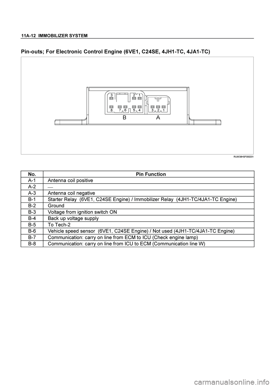
Pin-outs; For Electronic Control Engine (6VE1, C24SE, 4JH1-TC, 4JA1-TC)
RUW38HSF000201
No. Pin Function
A-1 Antenna coil positive
A-2
�
A-3 Antenna coil negative
B-1 Starter Relay (6VE1, C24SE Engine) / Immobilizer Relay (4JH1-TC/4JA1-TC Engine)
B-2 Ground
B-3 Voltage from ignition switch ON
B-4 Back up voltage supply
B-5 To Tech-2
B-6 Vehicle speed sensor (6VE1, C24SE Engine) / Not used (4JH1-TC/4JA1-TC Engine)
B-7 Communication: carry on line from ECM to ICU (Check engine lamp)
B-8 Communication: carry on line from ICU to ECM (Communication line W)
Page 3380 of 4264
 V
4 Accident Sensor (Crash Sensor) Ac")
11B – 34 ANTITHEFT SYSTEM
Tech-2 Data List
No. Streings Units
1 Battery Voltage V
2‘KEY-IN’ Status ON/OFF
3 CDLS-Motor Voltage (Central Door Locking System) V
4 Accident Sensor (Crash Sensor) Active/Inactive
5 Remote Key Active/Inactive
6 Remote-Key Detected Remote Key No.
7 Key Function Detected Lock/Unlock
8 Prev. Detected Remote-Key (Previously) Remote Key No.
9 Previously Key Function Lock/Unlock
10 Remote-Key 1 Status In Range/Not Programmed
11 Remote-Key 2 Status In Range/Not Programmed
12 Remote-Key 3 Status In Range/Not Programmed
13 Remote-Key 4 Status In Range/Not Programmed
14 Remote-Key 5 Status In Range/Not Programmed
15 Front Door Unlock Switch Active/Inactive
16 Front Door Lock Switch Active/Inactive
17 Front Door Lock Status Active/Inactive
18 Auto Door Unlock Switch Active/Inactive
19 Auto Door Lock Switch Active/Inactive
20 Auto Door Lock Status Active/Inactive
21 Trunk Signal Switch *Not used Open/Closed
22 Doorknob Switch Open/Closed
23 Doorknob Status Lock/Unlock
24 Trunk Doorknob Switch *Not used Open/Closed
25 Trunk Doorknob Status *Not used Lock/Unlock
26 Driver Door Switch Open/Closed
27 Driver Door Status Open/Closed
28 All Door Switch Open/Closed
29 All Door Status Open/Closed
30 Doorlock Tamper Switches Open/Closed
31 Engine Hood Switch Open/Closed
32 Engine Hood Status Open/Closed
33 Trunk Switch *Not used Open/Closed
34 Trunk Status *Not used Open/Closed
35 Pane Breakage Connected *Not used Yes/No
36 Pane Breakage Status *Not used Disabled/Abled
37 CDLS-Motor Current (Central Door Locking System) A
38 CDLS-Motor Unlock (Central Door Locking System) V
39 CDLS-Motor Lock (Central Door Locking System) V
40 Overflow Protection Active/Inactive
41 Turn Signal Active/Inactive
42 Horn Connected Yes/No
43 Horn Signal Active/Inactive
44 Theft LED ON/OFF
45 CDLS-Status (Central Door Locking System) Lock/Unlock
46 Selftest Request Active/Inactive
47 Last Use—
48 Theft Status Disabled/Abled
49 Alarm Status Active/Inactive
50 Security Wait Time Active/Inactive
Page 3510 of 4264

3C-18 FRONT SUSPENSION
6. Remove the stabilizer link nut. Right and left.
7. Remove the wheel speed sensor from the knuckle.
8. Remove back plate.
9. Remove lower ball joint by using remover 5-8840- 2017-0.
CAUTION: Be careful not to damage the ball joint
boot.
P1010009
10. Remove upper ball joint by using remover 5-8840-
2017-0.
CAUTION: Be careful not to damage the ball joint
boot.
P1010011
11. Remove knuckle.
Inspection and Repair
Make necessary correction or parts replacement if
wear, damage, corrosion or any other abnormal
condition are found through inspection.
Check the following parts:
�
Knuckle
�
Knuckle arm
Installation
1. Install knuckle assembly.
2. Install upper ball joint and tighten the nut to the
specified torque, with just enough additional torque
to align cotter pin holes. Install new cotter pin (1).
Torque: 98 N �
��
�
m (10.0kg �
��
�
m/72 lb ft)
3. Install lower ball joint and tighten the nut to the specified torque, with just enough additional torque
to align cotter pin holes. Install new cotter pin (4).
Torque: 147N �
��
�
m (15.0kg �
��
�
m/108 lb ft)
4. Install back plate.
5. Install wheel speed sensor.
6. Install stabilizer link nut. Right and left.
Page 3529 of 4264
FRONT SUSPENSION 3C-37
Knuckle
Knuckle and Associated Parts
RTW340LF001301
Legend
(1) Torsion Bar
(2 )Lower Ball Joint, Nut and Cotter Pin
(3) Back Plate
(4) Knuckle Assembly
(5) Knuckle
(6) Needle Bearing (4�4 Model Only)
(7) Thrust Washer (4�4 Model Only)
(8) Oil Seal (4�
4 Model Only)
(9) Upper Ball Joint, Nut and Cotter Pin
(10) Speed Sensor harness
Removal
1. Raise the vehicle and support the frame with
suitable safety stands.
2. Remove wheel and tire assembly. Refer to Wheel
in this section.
3. Remove the brake caliper. Refer to Disc Brakes in
Brake section.
Page 3530 of 4264
3C-38 FRONT SUSPENSION
4. Remove the hub assembly. Refer to Front Hub
and Disk in this section.
5. Remove tie-rod end from the knuckle. Refer to
Power Steering Unit in Steering section.
6. Remove the speed sensor from the knuckle.
7. Loosen torsion bar by height control arm adjust
bolt, then remove torsion bar. Refer to Torsion Ba
r
in this section.
8. Remove speed sensor harness.
9. Remove back plate.
10. Remove lower ball joint by using remover 5-8840-
2005-0.
CAUTION: Be careful not to damage the ball joint
boot.
901RW271
11. Remove upper ball joint by using remover 5-8840-
2121-0.
CAUTION: Be careful not to damage the ball joint
boot.
901RW272
12. Remove knuckle assembly.
13. Remove oil seal. If replacement required.
(4�
4 Model Only)
14. Remove washer. If replacement required.
(4�
4 Model Only)
15. Remove needle bearing by using remover 5-8840-
2000-0 and sliding hammer 5-8840-0019-0.
If replacement required. (4�
4 Model Only)
(4�
4 Model Only)
RTW340SH00401
Page 3531 of 4264

FRONT SUSPENSION 3C-39
Inspection and Repair
Make necessary correction or parts replacement if
wear, damage, corrosion or any other abnormal
condition are found through inspection.
Check the following parts:
�
Knuckle
�
Knuckle arm
� Thrust washer (4�4 Model Only)
Installation
1. Apply appropriate amount of multipurpose type
grease to the new bearing (Approx. 5 g) and
install needle bearing by using installer 5-8840-
2128-0 and grip 5-8840-0007-0. (4�
4 Model Only)
(4�4 Model Only)
901RW275
2. Apply multipurpose type grease to the thrust
washer, and install washer with chamfered side
facing knuckle. (4�4 Model Only)
3. Use a new oil seal, and apply multipurpose type
grease to the area surrounded by the lip (approx. 2
g). Then use installer 5-8840-2127-0 and grip 5-
8840-0007-0 to install oil seal. After fitting the oil
seal to the installer, drive it to the knuckle using a
hammer or bench press until the tool front face
contacts with the thrust washer. (4�
4 Model Only)
(4�4 Model Only)
901RW274
4. Install knuckle assembly.
5. Install upper ball joint and tighten the nut to the
specified torque, with just enough additional torque
to align cotter pin holes. Install new cotter pin (9).
Torque: 98 N�
�� �m (10.0kg�
�� �m/72 lb ft)
6. Install lower ball joint and tighten the nut to the
specified torque, with just enough additional torque
to align cotter pin holes. Install new cotter pin (2).
Torque: 147 N
�
�� �m (15.0kg
�
�� �m/108 lb ft)
7. Install back plate.
8. Install speed sensor harness.
9. Install torsion bar, refer to Torsion Bar in this
section.
NOTE: Adjust the trim height. Refer to Front End
Alignment Inspection and Adjustment in Steering.
.
7. Raise and support vehicle with suitable stands.
8. Remove rear propeller shaft (6).
NOTE: Apply alignment marks on the fl")
 Torsion Bar
(2 )Lower Ball Joint, Nut and Cotter Pin
(3) Back Plate
(4) Knuckle Assembly")
