Page 3131 of 4264

MSG MODEL 7B-13
Starter Motor
1. Install the starter motor to the engine rear plate.
2. Tighten the starter motor bolts to the specified torque.
Starter Motor Torque N�
m (kgf�
m/lb�
ft)
78 (8.0 / 58)
Slave Cylinder
Install the slave cylinder to the transmission case.
Slave Cylinder Bolt Torque N�
m (kgf�
m/lb�
ft
)
78 (8.0 / 58)
Harness Connector
Connect the back up light switch connector and speedometer
sensor connector.
Rear Propeller Shaft (Single Shaft Type)
1. Insert the splined yoke 1 with the propeller shaft into the
transmission main shaft spline
2 .
2. Install the propeller shaft flange yoke
3 to the drive pinion
side.
3. Tighten the propeller shaft flange yoke bolt to the specified
torque.
Propeller Shaft Flange Yoke Bolt Torque N�m (kgf�m/lb�ft)
M8 : 35.3 (3.6 / 26)
M10 : 62.7 (6.4 / 46.3)
Rear Propeller Shaft (Dual Shaft Type)
1. Place the center bearing and retainer 1 together with the
1st propeller shaft
2 and 2nd propeller shaft 7 on the No.4
crossmember
3.
2. Insert the splined yoke
4into the transmission main shaft
spline
5.
3. Tighten the center bearing retainer bolts
6 to the specified
torque.
Center Bearing Retainer Bolt Torque N�
m (kgf�
m/lb�
ft)
60.8 (6.2 / 44.8)
4. Connect the 2nd propeller shaft
7 and drive pinion side 8.
Be sure to align the setting marks applied at disassembly.
5. Tighten the coupling bolts to the specified torque.
Propeller Shaft Flange Yoke Bolt
Torque N�
m (kgf�
m/lb�
ft)
M8 : 35.3 (3.6 / 26)
M10 : 62.7 (6.4 / 46.3)
Page 3133 of 4264
MSG MODEL 7B-15
DISASSEMBLY
MAJOR COMPONENTS
RTW47BLF000301
Disassembly Steps
1. Clutch shift block and release bearing
2. Clutch shift fork
3. Speedometer sensor
4. Speedometer driven gear assembly
5. Gear control box assembly
�
6. Front cover with oil seal
�
7. Counter gear snap ring
�
8. Bearing snap ring
9. Rear cover with oil seal
10. Transmission case
11. Intermediate plate with gear assembly
Page 3158 of 4264
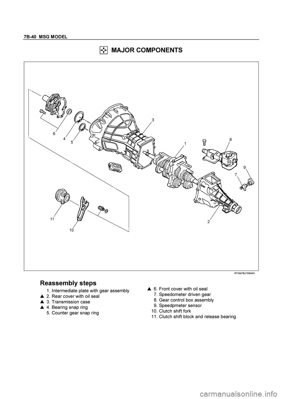
7B-40 MSG MODEL
MAJOR COMPONENTS
RTW47BLF000401
Reassembly steps
1. Intermediate plate with gear assembly
�
2. Rear cover with oil seal
�
3. Transmission case
�
4. Bearing snap ring
5. Counter gear snap ring
�
6. Front cover with oil seal
7. Speedometer driven gear
8. Gear control box assembly
9. Speedpmeter sensor
10. Clutch shift fork
11. Clutch shift block and release bearing
Page 3173 of 4264
MANUAL TRANSMISSION 7B1-9
6. Remove gear control lever (5).
7. Raise and support vehicle with suitable stands.
8. Remove rear propeller shaft (6).
NOTE: Apply alignment marks on the flange at the
differential side.
401RS023
9. Loosen the front exhaust pipe fixing nuts (7) at the
engine side but not remove them. (Diesel engine
only)
150R300003
10. Remove the exhaust pipe (8). (6VE1 only)
RTW37ASH0001
11. Disconnect harness connectors and clips on the
transmission.
� Neutral Switch
�
Back up Switch
� Car Speed Sensor
12. Remove the fuel pipe bracket (9) with pipes from the
transmission (17).
Diesel engine
220R300012
Legend
(1) Bolt
(2) Nut
(3) Fuel Pipe Assembly
Page 3180 of 4264
. (Diesel engine only)
NOTE: Tighten the lower bolt temporarily.
After installing the fuel pipe assembly, tighten the bolt to
the specified")
7B1-16 MANUAL TRANSMISSION
6. Install starter(15). (Diesel engine only)
NOTE: Tighten the lower bolt temporarily.
After installing the fuel pipe assembly, tighten the bolt to
the specified torque.
Torque: 76 N�
�� �m (7.7 kg�
�� �m/56 lb�
�� �ft)
7. Install the rear support rubber (14) on the
transmission and tighten the nuts to the specified
torque.
Torque: 52 N�
�� �m (5.3 kg�
�� �m/38 lb�
�� �ft)
8. Install the middle part of transmission crossmember
(12) and bolts.
Tighten the nuts to the specified torque.
Torque: 67 N�
�� �m (6.8 kg�
�� �m/49 lb�
�� �ft)
9. Install engine rear mount nuts (11) fixing on
transmission crossmember (12).
Torque: 52 N�
�� �m (5.3 kg�
�� �m/38 lb�
�� �ft)
Remove the transmission jack from transmission
side.
10. Apply grease to top hole portion of the shift fork.
Install slave cylinder (10) and tighten the bolts to the
specified torque.
Torque: 76 N�
�� �m (7.7 kg�
�� �m/56 lb�
�� �ft)
11. Install the fuel pipe brackets (9) on the transmission.
Install the fuel pipe assembly to the fuel brackets.
Torque: Bolt & Nut 76 N�
�� �m (7.7 kg�
�� �m/56 lb�
�� �ft)
Nut 37 N�
�� �
m (3.8 kg�
�� �
m/28 lb�
�� �
ft)
Diesel engine
220R300012
Legend
(1) Bolt
(2) Nut
(3) Fuel Pipe Assembly
6VE1, C24NE
Scan-1
12. Connect transmission harness connectors and clip.
Connector: neutral switch, car speed sensor, and
backup switch.
13. Tighten exhaust pipe fixing nuts (7) to the specified
torque. (Diesel engine only)
Torque: 67 N�
�� �m (6.8 kg�
�� �m/49 lb�
�� �ft)
150R300003
Page 3182 of 4264
7B1-18 MANUAL TRANSMISSION
Transmission Case
Major Component
RTW37BLF0005
Legend
(1) Gear Control Box Assembly and Gasket (9) Front Cover (with Oil Seal)
(2) Speedometer Sensor and Driven Gear (10) Top Gear Bearing Snap Ring
(3) Rear Cover Assembly (11) Release Bearing : C24NE
(4) Intermediate Plate with Gear Assembly (12) Shift Fork : C24NE
(5) Transmission Case (13) Fulcrum Bridge : 6VE1
(6) Release Bearing (with Spring) : Diesel engine (14) Release Bearing : 6VE1
(7) Shift Fork : Diesel engine (15) Shift Fork : 6VE1
(8) Counter Front Bearing Snap Ring
Page 3183 of 4264

MANUAL TRANSMISSION 7B1-19
Disassembly
1. Clean the exterior of the unit with solvent.
2. Remove the drain plug from the transmission case
and drain the lubricant.
3. Remove the clutch release bearing with spring
(6)(11) from the transmission case.
4. Remove the shift fork (7)(12), and boot. (Diesel
engine, C24NE)
5. Remove the shift fork snap pin. (6VE1)
6. Remove the shift fork pin and shift fork from the
fulcrum bridge. (6VE1)
RTW47BSH000601
Legend
(1) Shift fork pin
(2) Shift fork
(3) Release bearing
7. Remove the fulcrum bridge from the transmission
case. (6VE1)
RTW37ASH0002
Legend
(1) Fulcrum bridge
8. Remove the front cover (9) and gasket from the
transmission case.
9. Remove snap ring (8) fixing counter front bearing.
10. Use a pair of snap ring pliers to remove the snap
ring (10) fixing top gear bearing.
226RS001
11. Remove the speedometer sensor (2).
Remove the plate (2).
Remove the driven gear bushing and driven gear
(2).
NOTE : Apply a reference mark to the driven gear
bushing before removal.
12. Remove gear control box assembly (1).
Page 3185 of 4264
.
Torque: 27 N�
�� �m (2.8 kg�
�� �m/20 lb�
�� �ft)
225R300001
8. Install top gear bearing snap ring (10) and counter
front")
MANUAL TRANSMISSION 7B1-21
7. Install the speedometer sensor (2).
Torque: 27 N�
�� �m (2.8 kg�
�� �m/20 lb�
�� �ft)
225R300001
8. Install top gear bearing snap ring (10) and counter
front bearing snap ring (8).
�
Use a pair of snap ring pliers to install the snap
rings to the mainshaft and countershaft.
�
The snap rings must be fully inserted into the
bearing snap ring groove.
9. Front cover with oil seal (9).
Front Cover Oil Seal Replacement
�
Remove the oil seal from the front cover.
�
Apply engine oil to a new oil seal outer
circumference.
�
Apply recommended grease to the oil seal lip.
�
Use the oil seal installer 5-8840-0026-0 to install
the oil seal to the front cover.
220R3000020
10. Install a new gasket and front cover (9) to the
transmission case.
NOTE: Take care not to damage the oil seal.
Notes When Tightening the Bolt:
�
After cleaning the bolt hole, dry it thoroughly with air.
�
After cleaning the screw face of a removed bolt or
new one, dry it thoroughly. Apply recommended
liquid gasket (LOCTITE 242) or its equivalent before
tightening it.
Tighten six front cover bolts to the specified torque.
Torque: 25 N�
�� �
m (2.6 kg�
�� �
m/19 lb�
�� �
ft)
11. Apply molybdenum disulfide type grease to the
areas as shown in the figure and install shift fork (7).
(Diesel engine, C24NE)
F07L100026

.
7. Raise and support vehicle with suitable stands.
8. Remove rear propeller shaft (6).
NOTE: Apply alignment marks on the fla")
 Gear Control Box Assembly and Gasket (9) Front Cover (with Oil Seal)
(2) Speedometer Sensor and Dri")