Page 2887 of 4264
INDUCTION 6J-3
Installation
1. Install air cleaner element.
2.
Attach the air cleaner duct cover to the body completely,
then clamp it with the clip.
3. Install mass air flow sensor.
4. Install mass air temperature sensor.
5. Install positive crankcase ventilation hose connector.
Page 2990 of 4264

Items followed by an asterisk (*) require more frequent maintenance if the vehicle is driven under severe conditions.
Ref")
0B-2 MAINTENANCE AND LUBRICATION
MAINTENANCE SCHEDULE (For GENERAL EXPORT)
Items followed by an asterisk (*) require more frequent maintenance if the vehicle is driven under severe conditions.
Refer to "SEVERE CONDITIONS MAINTENANCE SCHEDULE."
I : Inspect and correct or replace as necessary A : Adjust
R : Replace or change T : Tighten to specified torque L : Lubricate
SERVICE INTERVAL:
� 1,000 km 5 10 15 20 25 30 35 40 45 50 55 60 65 70 75 80 85 90 95 100(Use odometer reading � 1,000 miles 3 6 9 12 15 18 21 24 27 30 33 36 39 42 45 48 51 54 57 60or months whichever
comes fi rst)
or months 6 12 18 24 30 36 42 48 54 60 66 72 78 84 90 96 102 108 114 120
ENGINE Idling speed and acceleration
(GASOLINE) I I - I - I - I - I - I - I - I - I - I
(DIESEL) I I I I I I I I I I I I I I I I I I I I * Air cleaner element
(GASOLINE) - I - I - I - R - I - I - I - R - I - I
(DIESEL) I I I I I I I R I I I I I I I R I I I I * P Engine oil (6VE1) - R - R - R - R - R - R - R - R - R - R * P Engine oil (C24SE) Replace every 12,000km * D Engine oil (4JH1-TC) - R - R - R - R - R - R - R - R - R - R * D Engine oil (4JA1-TC) - - R - - R - - R - - R - - R - - R - - * D Engine oil (4JA1-T) RR R R RR RRRRRRRR R R R RRR * P Engine oil filter (6VE1) - R - R - R - R - R - R - R - R - R - R * P Engine oil filter (C24SE) Replace every 12,000km * D Engine oil filter (4JH1-TC, 4JA1-T) - R - R - R - R - R - R - R - R - R - R * D Engine oil filter (4JA1-TC) - - R - - R - - R - - R - - R - - R - - Oil leakage and contamination
(GASOLINE) - I - I - I - I - I - I - I - I - I - I
(DIESEL) I I I I I I I I I I I I I I I I I I I I Fuel leakage I I - I - I - I - I - I - I - I - I - I Fuel tank - - - | - - - | - - - | - - - | - - - | P O2 Sensor Replace every 160,000km P Valve clearances (6VE1) Check and adjust if noisy D Valve clearances A - - A - - - A - - - A - - - A - - - A P Spark plugs (C24SE) (for leaded
fuel use) - R - R - R - R - R - R - R - R - R - R
P Spark plugs (C24SE) (for unleaded
fuel use) - - - - - R - - - - - R - - - - - R - -
P Spark plugs (6VE1) Replace every 160,000km Spark plug wire | | - | - | - | - | - | - | - | - | - | Fuel filter (GASOLINE) - - - R - - - R - - - R - - - R - - - R Fuel filter (DIESEL) - - R - - R - - R - - R - - R - - R - - Engi ne / Accessory dri ve belt
(GASOLINE) - - - - - - - - - R - - - - - - - - - R
Fan belt tension and damage
(DIESEL) I I I I I I I I I I I I I I I I I I I I
* Exhaust system I I - I - I - I - I - I - I - I - I - I Engine coolant concentration (6VE1) - - - - - - - - - R - - - - - - - - - R (C24SE) - | - | - | - | - R - | - | - | - | - R Engine coolant level concentration
(DESEL) I I I I I I I I I R I I I I I I I I I R
Cooli ng sy stem for water l eakage - I - I - I - I - I - I - I - I - I - I All hoses and pipes in engine
compartment for clogs or damage - I - I - I - I - I - I - I - I - I - I
P Timing belt (C24SE) - - - - - - - - - - - - - - - I - - - - (Replace every 120,000km) P Timing belt (6VE1) Replace every 160,000km CLUTCH Cl utch fl ui d I I - I - I - I - I - I - I - I - I - I Clutch pedal travel and free play I I - I - I - I - I - I - I - I - I - I
Page 3060 of 4264
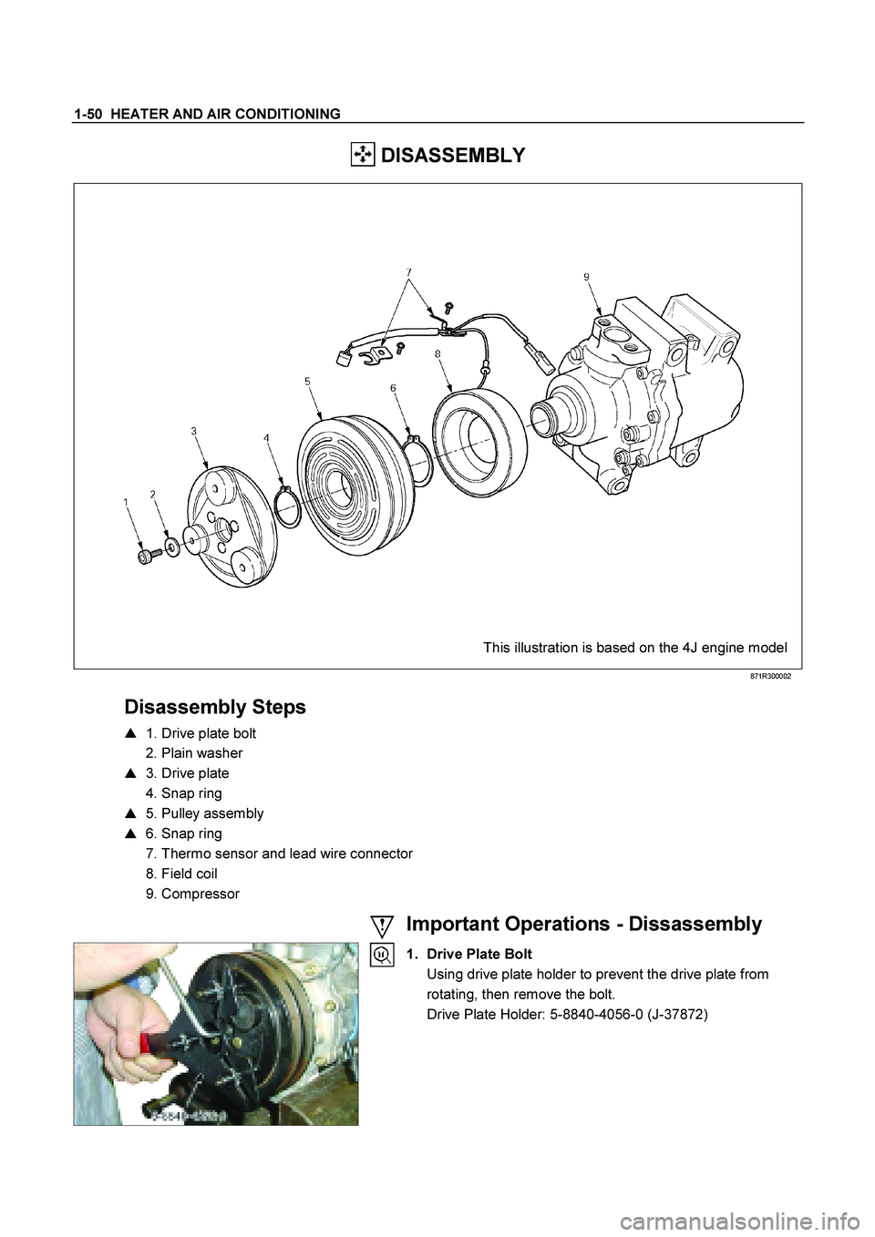
1-50 HEATER AND AIR CONDITIONING
DISASSEMBLY
This illustration is based on the 4J engine model
871R300002
Disassembly Steps
� 1. Drive plate bolt
2. Plain washer
� 3. Drive plate
4. Snap ring
� 5. Pulley assembly
� 6. Snap ring
7. Thermo sensor and lead wire connector
8. Field coil
9. Compressor
Important Operations - Dissassembly
1. Drive Plate Bolt
Using drive plate holder to prevent the drive plate from rotating, then remove the bolt.
Drive Plate Holder: 5-8840-4056-0 (J-37872)
Page 3062 of 4264
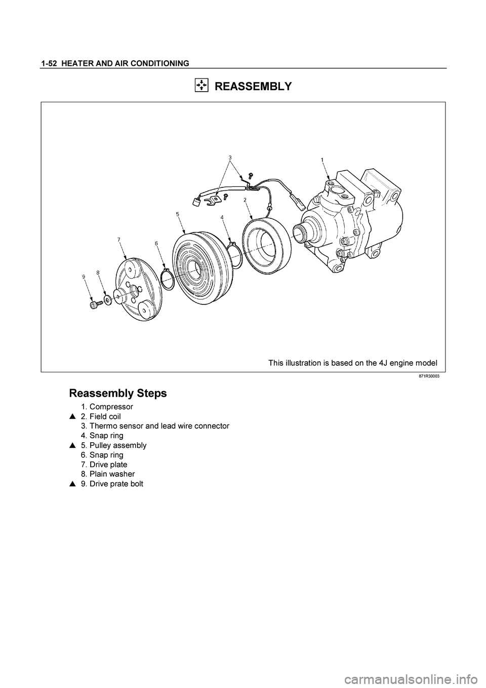
1-52 HEATER AND AIR CONDITIONING
REASSEMBLY
This illustration is based on the 4J engine model
871R30003
Reassembly Steps
1. Compressor
� 2. Field coil
3. Thermo sensor and lead wire connector
4. Snap ring
� 5. Pulley assembly
6. Snap ring
7. Drive plate
8. Plain washer
� 9. Drive prate bolt
Page 3072 of 4264
1-62 HEATER AND AIR CONDITIONING
This illustration is based on RHD model
Important Operation -Reassembly
6. Electronic Thermostat
1) Install the electronic thermostat to the evaporator core
specified position with the clip.
2) Sensor part must not interfere with the evaporator core.
Page 3095 of 4264

pressure
gauge
abnormally
high Reduced or no air flow through
the condenser
��
Condenser clogged o")
HEATER AND AIR CONDITIONING 1-85
RESULT SYMPTOM TROUBLE CAUSE CORRECTION
Discharge
(High)
pressure
gauge
abnormally
high Reduced or no air flow through
the condenser
��
Condenser clogged or dirty
��
Radiator (condenser) fan
does not operate properly ��
Clean
��
Check cooling fan
operation
No bubbles in sight glass when
condenser is cooled by water
(Insufficient cooling)
��Excessive refrigerant in
system
��Check sight glass.
(See “Reading Sight
Glass”)
��
Discharge and
recover refrigerant.
Recharge to specified
amount
After stopping air conditioning,
pressure drops approx. 196 kPa
(2.0kg/cm
2 / 28 PSI) quickly ��
Air in system
��
Evacuate and charge
refrigerant system
Discharge
(High)
pressure
gauge
abnormally
low Insufficient cooling and excessive
bubbles in the sight glass
��
Insufficient refrigerant in
system
��
Check sight glass.
(See “Reading Sight
Glass”)
��Check for leaks
��
Discharge and
recover refrigerant.
Recharge to specified
amount
Low pressure gauge indicates
vacuum ��
Clogged or defective
expansion valve ��
Replace the
expansion valve
Frost or dew on refrigerant line
before and after receiver/ drier or
expansion valve, and low pres-
sure gauge indicates vacuum ��Restriction caused by debris
or moisture in receiver/drier
��Check system for
restriction and
replace receiver/drier
After turning off air conditioning,
high and low pressure gauge
balanced quickly
��
Compressor seal defective
��
Poor compression due to
defective compressor
gasket ��
Replace or repair
compressor
Suction
(Low)
pressure
gauge
abnormally
high Low pressure gauge is lowered
after condenser is cooled by
water
��
Excessive refrigerant in
system
��
Discharge and
recover refrigerant
Recharge to specified
amount
Low pressure hose temperature
around the compressor refrigerant
line connector is lower than
around evaporator
��
Unsatisfactory valve
operation due to defective
temperature sensor of
expansion valve
��
Expansion valve opens too
long ��
Replace the
expansion valve
After turning off air conditioning,
high and low pressure gauge is
balanced quickly ��
Compressor gasket is
defective
��
Replace
Air conditioning turns off before
passenger compartment is
sufficiently
cool ��Electronic thermostat
defective
��Check the electronic
thermostat and
replace as necessary
* For the charging and discharging operations in the table above, refer to “RECOVERY, RECYCLING,
EVACUATION AND CHARGING” in this section.
Page 3096 of 4264

pres-sure
abnormally
low
Condenser is not hot and
excessive bubble in sight glass
��
Insuf")
1-86 HEATER AND AIR CONDITIONING
RESULT SYMPTOM TROUBLE CAUSE CORRECTION
Suction
(Low)
pres-sure
abnormally
low
Condenser is not hot and
excessive bubble in sight glass
��
Insufficient refrigerant
��
Check sight
glass.(See “Reading
Sight Glass”)
��
Check for leaks
��
Discharge and
recover refrigerant.
Recharge to specified
amount
Frost on the expansion valve inlet
line ��
Expansion valve clogged
��
Replace the
expansion valve
A distinct difference in
temperature between the inlet and
outlet refrigerant lines of the
receiver/drier ��
Receiver/drier clogged
��
Replace the receiver/
drier
Expansion valve outlet refrigerant
line is not cold and low-pressure
gauge indicates vacuum
��
The temperature sensor of
the expansion valve is
defective, and the valve
cannot regulate the correct
flow of the refrigerant ��
Replace the
expansion valve
Discharge temperature is low and
air flow from vents is restricted
��Frozen evaporator core fins
��Check electronic
thermostat and
replace as necessary
Low-pressure gauge reading is
low, or a vacuum reading may be
shown ��
Clogged or blocked
refrigerant line
��
Replace refrigerant
line
Suction
(Low) and
Discharge
(High)
pressure
abnor-
mally
high
No bubbles in sight glass after
condenser is cooled by water
(Insufficient cooling)
��
Excessive refrigerant in
system
��
Check sight
glass.(See “Reading
Sight Glass”)
��
Discharge and
recover refrigerant.
Recharge to specified
amount
Reduce air flow through con-
denser
��
Condenser clogged
��Radiator (condenser) fan
does not rotate properly ��
Clean
��Check cooling fan
operation
Suction (Low) pressure hose is
not cold ��
Air in system ��
Evacuate and charge
refrigerant
Suction
(Low) and
Discharge
(High)
pres-sure
abnor-
mally
low
Insufficient cooling and excessive
bubbles in the sight glass ��
Insufficient refrigerant in
system
��
Check sight glass.
(See “Reading Sight
Glass”)
��
Check for leaks
��Discharge and
recover refrigerant.
Recharge to specified
amount
Page 3126 of 4264
7B-8 MSG MODEL
Exhaust Pipe
1. Remove the exhaust pipe bracket from the transmission
case.
2. Remove the exhaust pipe.
Rear Propeller Shaft (Single Shaft Type)
1. Remove the propeller shaft flange yoke at the drive pinion
side
1.
2. Remove the propeller shaft from the transmission main
shaft spline
2.
Rear Propeller Shaft (Dual Shaft Type)
1. Apply setting marks to the 2nd propeller shaft flange yoke.
This will prevent mispositioning during the installation
procedure.
2. Remove the 2nd propeller shaft flange yoke bolts at the
drive pinion side
1.
3. Remove the center bearing retainer bolts
2 .
4. Remove the 1st propeller shaft with the center bearing and
the 2nd propeller shaft.
Pull the 1st propeller shaft toward the rear of the vehicle
until the spline yoke is free of the transmission main shaft.
Harness Connector
Disconnect the back up light switch connector and the
speedometer sensor connector.
Slave Cylinder
Remove the slave cylinder from the transmission case.

 Install the electronic thermostat to the evaporator core
sp")

1. Remove the p")