Page 272 of 4264
4C1-52 FRONT WHEEL DRIVE
INSPECTION AND REPAIR
Make necessary correction or parts replacement if wear, damage or any other abnormal conditions are found
through inspection.
For inspection and servicing of disc caliper, and relative parts, and ABS parts, refer to Section Brakes.
�
Hub
�
Hub bearing, oil seal
�
Knuckle spindle
�
Disc
�
Caliper
�
ABS sensor rotor
� Cap, Hub flange, Shim, Snap ring
Visual Check
Check the following parts for wear, damage or other abnormal
conditions.
Page 280 of 4264
4C1-60 FRONT WHEEL DRIVE
INSPECTION AND REPAIR
Make necessary correction or parts replacement if wear, damage or any other abnormal conditions are found
through inspection.
For inspection and servicing of disc caliper, and relative parts, and ABS parts, refer to Section Brakes.
�
Hub
� Hub bearing, oil seal
�
Knuckle spindle
�
Disc
�
Caliper
�
ABS sensor rotor
�
Cap, Hub flange, Shim, Snap ring
�
Free wheeling hub parts (Option)
� Clutch, Knob, follower, inner, ring and
spring
Visual Check
Check the following parts for wear, damage or other abnormal
conditions.
Page 344 of 4264

5A-28 BRAKE CONTROL SYSTEM
Isolation Valve Test
Purpose: The purpose of this test is to detect brake
pipe and valve line harness wire for wrong connections
and valve trouble.
This test will help you confirm the result of your repair
service including the removal/reinstallation of brake
pipe, valve line harness and valve.
Test conditions: The ignition key is in the “ON” position
with the four wheels lifted up. The brake pedal is
stepped on, released and stepped on again with the
parking brake released.
Test procedure:
1. Connect Tech 2 with the vehicle, and select
Actuaor Test from the menus.
2. Select a Solenoid Valve Test Menu from the
Actuaor Test Menus.
060L300002
3. Select Isolation Valve from the Valve Select Menus.
4. Step on the brake pedal.
5. Release the brake pedal.
6. Make sure that the Isolation Valve “ON” aimed at by
Tech 2 and the wheel locked position are the same.
If different, check brake pipe, valve line harness
wiring and H/UNIT. Repair is needed if abnormality
is found.
7. Conduct Step 2 through Step 5 above on all the
four wheels.
060L300002
CAUTION: When conducting this test, please
observe the following cautions.
1. Do not start the engine.
2. Lift up the vehicle at a level floor.
�
�� � Secure a clearance from the floor surface
enough to allow the lifted tire to rotate.
3. Maintain the lift up.
4. Wipe the floor surface to remove water and oil
so that the surface may become unslippery.
5. Do not load the vehicle.
�
�� � When lifting up the vehicle, be sure to
observe the lifting up points. Refer to
vehicle lifting points in 0A section.
Page 345 of 4264

BRAKE CONTROL SYSTEM 5A-29
Dump Valve Test
Purpose: The purpose of this test is to detect brake
pipe and valve line harness wire for wrong connections
and valve trouble.
This test will help you confirm the result of your repai
r
service including the removal/reinstallation of brake
pipe, valve line harness and valve.
Test conditions: The ignition key is in the “ON” position
with the four wheels lifted up. The brake pedal is
stepped on, released and stepped on again with the
parking brake released.
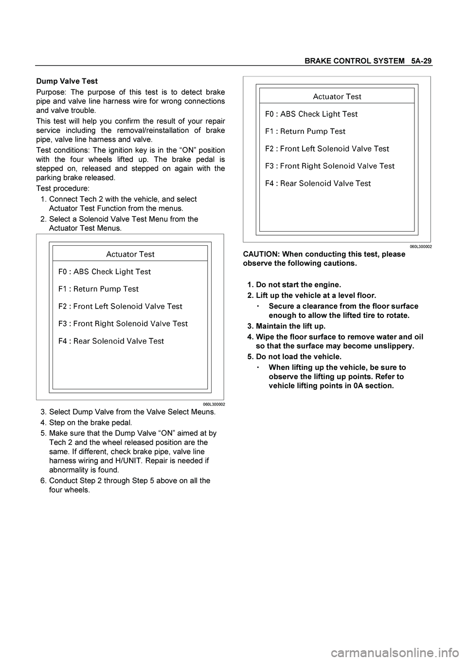
Test procedure:
1. Connect Tech 2 with the vehicle, and select
Actuator Test Function from the menus.
2. Select a Solenoid Valve Test Menu from the
Actuator Test Menus.
060L300002
3. Select Dump Valve from the Valve Select Meuns.
4. Step on the brake pedal.
5. Make sure that the Dump Valve “ON” aimed at by
Tech 2 and the wheel released position are the
same. If different, check brake pipe, valve line
harness wiring and H/UNIT. Repair is needed if
abnormality is found.
6. Conduct Step 2 through Step 5 above on all the
four wheels.
060L300002
CAUTION: When conducting this test, please
observe the following cautions.
1. Do not start the engine.
2. Lift up the vehicle at a level floor.
�
�� � Secure a clearance from the floor surface
enough to allow the lifted tire to rotate.
3. Maintain the lift up.
4. Wipe the floor surface to remove water and oil
so that the surface may become unslippery.
5. Do not load the vehicle.
�
�� � When lifting up the vehicle, be sure to
observe the lifting up points. Refer to
vehicle lifting points in 0A section.
Page 346 of 4264

5A-30 BRAKE CONTROL SYSTEM
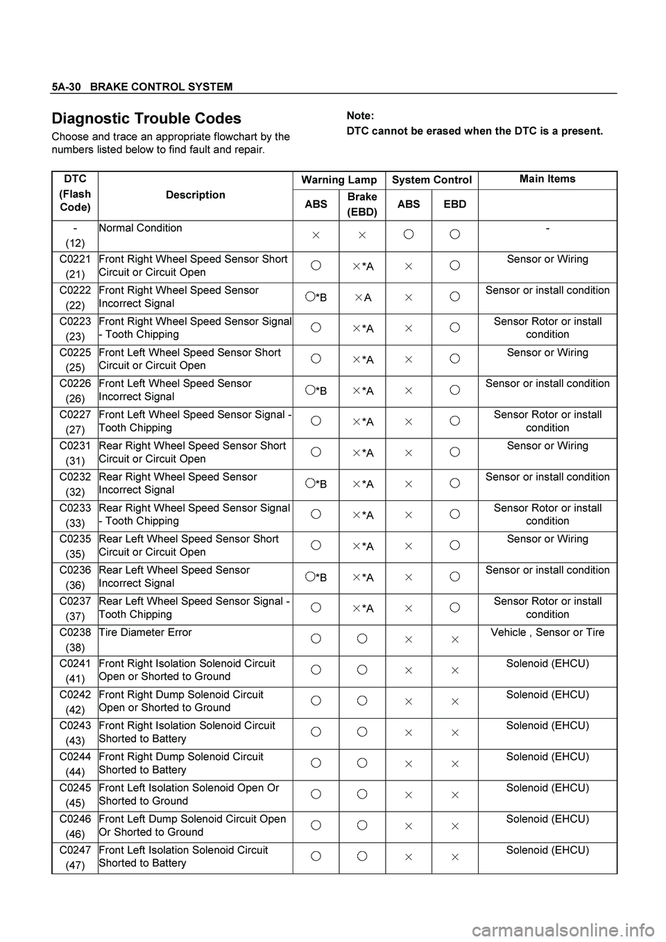
Diagnostic Trouble Codes
Choose and trace an appropriate flowchart by the
numbers listed below to find fault and repair.
Note:
DTC cannot be erased when the DTC is a present.
Warning Lamp System Control Main Items
DTC
(Flash
Code) Description
ABS Brake
(EBD)ABS EBD
-
(12) Normal Condition
�
�
-
C0221
(21) Front Right Wheel Speed Sensor Short
Circuit or Circuit Open �
*A �
Sensor or Wiring
C0222
(22) Front Right Wheel Speed Sensor
Incorrect Signal *B �
A �
Sensor or install condition
C0223
(23) Front Right Wheel Speed Sensor Signal
- Tooth Chipping �
*A �
Sensor Rotor or install
condition
C0225
(25) Front Left Wheel Speed Sensor Short
Circuit or Circuit Open �
*A �
Sensor or Wiring
C0226
(26) Front Left Wheel Speed Sensor
Incorrect Signal *B �
*A �
Sensor or install condition
C0227
(27) Front Left Wheel Speed Sensor Signal -
Tooth Chipping �
*A �
Sensor Rotor or install
condition
C0231
(31) Rear Right Wheel Speed Sensor Short
Circuit or Circuit Open �
*A �
Sensor or Wiring
C0232
(32) Rear Right Wheel Speed Sensor
Incorrect Signal *B �
*A �
Sensor or install condition
C0233
(33) Rear Right Wheel Speed Sensor Signal
- Tooth Chipping �
*A �
Sensor Rotor or install
condition
C0235
(35) Rear Left Wheel Speed Sensor Short
Circuit or Circuit Open �
*A �
Sensor or Wiring
C0236
(36) Rear Left Wheel Speed Sensor
Incorrect Signal *B �
*A �
Sensor or install condition
C0237
(37) Rear Left Wheel Speed Sensor Signal -
Tooth Chipping �
*A �
Sensor Rotor or install
condition
C0238
(38) Tire Diameter Error �
�
Vehicle , Sensor or Tire
C0241
(41) Front Right Isolation Solenoid Circuit
Open or Shorted to Ground �
�
Solenoid (EHCU)
C0242
(42) Front Right Dump Solenoid Circuit
Open or Shorted to Ground �
�
Solenoid (EHCU)
C0243
(43) Front Right Isolation Solenoid Circuit
Shorted to Battery �
�
Solenoid (EHCU)
C0244
(44) Front Right Dump Solenoid Circuit
Shorted to Battery �
�
Solenoid (EHCU)
C0245
(45) Front Left Isolation Solenoid Open Or
Shorted to Ground �
�
Solenoid (EHCU)
C0246
(46) Front Left Dump Solenoid Circuit Open
Or Shorted to Ground �
�
Solenoid (EHCU)
C0247
(47) Front Left Isolation Solenoid Circuit
Shorted to Battery �
�
Solenoid (EHCU)
Page 358 of 4264

5A-42 BRAKE CONTROL SYSTEM
Braking Sound (From EHCU) Is Heard While Not Braking
Step Action Value(s) Yes No
1 Is this the first vehicle start after engine start?
- It is self
checking
sound
Normal. Go to Step 2
2 Is vehicle speed under 10 km/h?
- It is self
checking
sound
Normal. Go to Step 3
3 Check for the following condition:
At the time of shift down or clutch operation.
At the time of low road friction drive (ice or snow
road) or rough road drive.
At the time of high-speed turn.
At the time of passing curb.
At the time of operating electrical equipment
switches.
At the time of racing the engine.
Did it occur under any one condition above?
- ABS may
sometimes be
actuated even
when brake
pedal is not
applied. Go to Step 4
4 Is there play in each or any sensor/wheel speed
sensor rotor?
- Repair.
Go to Step 7 Go to Step 5
5 Damage or powdered iron sticking to each or any
sensor/wheel speed sensor rotor?
- Repair.
Go to Step 7 Go to Step 6
6 Is each sensor normal?
Note : Check the EHCU type for specification, the
EHCU is replaced.
(Specification; 2WD or 4WD Model)
- Check
harness/
connector for
suspected
disconnection
If no
disconnection
is found,
replace EHCU
Go to Step 7 Repair.
Go to Step 7
7 Reconnect all components, ensure all components
are properly mounted.
Was this step finished?
- Repeat the
“Basic
diagnostic
flow chart” Go to Step 7
Page 360 of 4264
5A-44 BRAKE CONTROL SYSTEM
DTC C0221 (Flash Code 21) Front Right Wheel Speed Sensor Short Circuit or
Circuit Open
LTW35AMF000101
Step Action
Value(s) Yes No
1 Was the “Basic Diagnostic Flow Chart” performed?
- Go to Step 2 Go to Basic
Diagnostic
Flow Chart
2 1. Check for a poor connection at the front right wheel
speed sensor harness connector.
2. Check installation condition for front right wheel
speed sensor.
3. If a problem is found, repair as necessary.
Was a problem found?
- Verify repair Go to Step 3
3 1. Ignition “OFF,” disconnect the EHCU and front right
wheel speed sensor.
2. Check the circuit between EHCU and front right
wheel speed sensor. (Circuit for an open, short to
ground,or short to voltage.)
3. If a problem is found, repair as necessary.
Was a problem found?
- Verify repair Go to Step 4
Page 362 of 4264

5A-46 BRAKE CONTROL SYSTEM
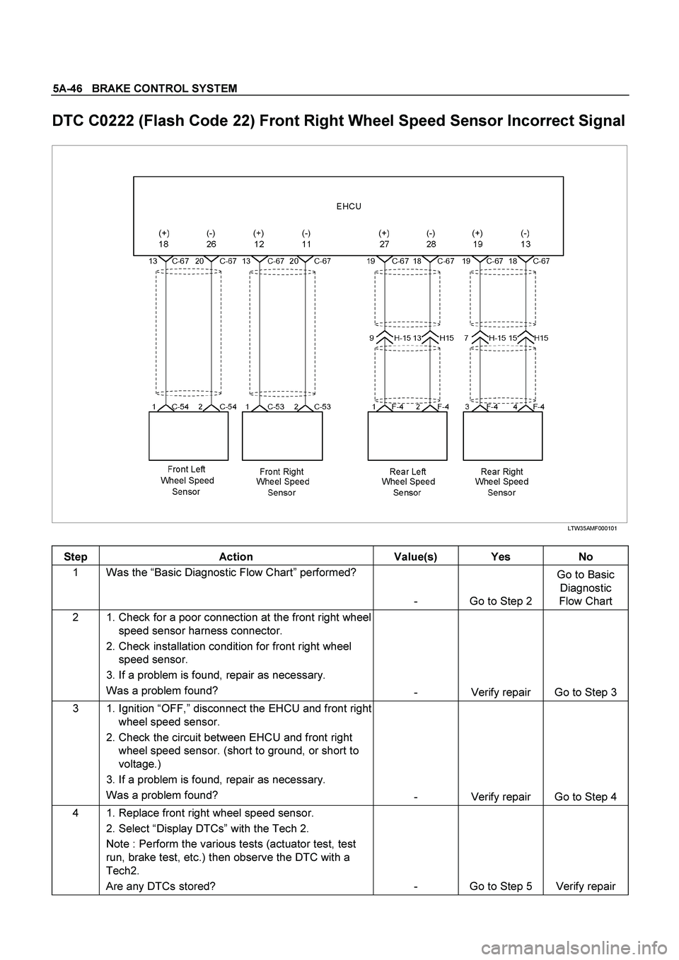
DTC C0222 (Flash Code 22) Front Right Wheel Speed Sensor Incorrect Signal
LTW35AMF000101
Step Action Value(s) Yes No
1 Was the “Basic Diagnostic Flow Chart” performed?
- Go to Step 2 Go to Basic
Diagnostic
Flow Chart
2 1. Check for a poor connection at the front right wheel
speed sensor harness connector.
2. Check installation condition for front right wheel
speed sensor.
3. If a problem is found, repair as necessary.
Was a problem found?
- Verify repair Go to Step 3
3 1. Ignition “OFF,” disconnect the EHCU and front right
wheel speed sensor.
2. Check the circuit between EHCU and front right
wheel speed sensor. (short to ground, or short to
voltage.)
3. If a problem is found, repair as necessary.
Was a problem found?
- Verify repair Go to Step 4
4 1. Replace front right wheel speed sensor.
2. Select “Display DTCs” with the Tech 2.
Note : Perform the various tests (actuator test, test
run, brake test, etc.) then observe the DTC with a
Tech2.
Are any DTCs stored? - Go to Step 5 Verify repair