Page 296 of 4264
4C1-76 FRONT WHEEL DRIVE
ITEM NO. ILLUSTRATION PART NO. PART NAME
FAL-41
5-8840-2089-0
(J-23597-9)
Nut & bolt
FAL-36
5-8840-2087-0
(J-23597-7)
Gauge plate
FAL-42
5-8840-0126-0
(J-8001)
Dial indicator
FAL-43
5-8840-0128-0
(J-23597-1)
Arbor
FAL-38
5-8840-2088-0
(J-23597-8)
Disc (2 pcs. required)
FAL-59
9-8522-1165-0
(J-6133-01)
Pinion bearing installer
(for 4WD)
FAL-52
9-8522-1275-0
(J-24250)
Pinion oil seal installer
FAL-56
9-8522-1164-0
(J-24244)
Side bearing installer
FAL-57
5-8522-0053-0
(J-29016)
Outer bearing installer
(for 2WD)
Page 297 of 4264
FRONT WHEEL DRIVE 4C1-77
ITEM NO. ILLUSTRATION PART NO. PART NAME
FAL-58
5-8522-0054-0
(J-29015)
Inner bearing installer
(for 2WD)
FAL-54
5-8522-0051-0
(J-33161)
Hub oil seal installer
(for 2WD)
FAL-62
5-8840-2117-0
(J-36827)
Hub nut wrench
FAL-17
5-8840-2119-0
(J-36829)
Outer bearing inner race
installer (for 4WD)
FAL-19
5-8840-2120-0
(J-36830)
Oil seal installer (for 4WD)
FAL-18
5-8522-0054-0
(J-29015)
Outer bearing outer race
installer (for 4WD)
FAL-61
5-8840-2137-0
(J-38194)
Inner cam installer
FAL-39
5-8840-2126-0
Auto locking shim gauge
(for 4WD)
FAL-60
5-8840-2125-0
Snap ring installer
(for 4WD)
Page 300 of 4264
4C2-2 SHIFT ON THE FLY SYSTEM
Shift On The Fly System
Outline of Shift on The Fly System
The shift on the fly system switches between 2 wheel
drive (2WD) and 4 wheel drive (4WD) electrically b
y
driver's pressing the 4WD switch (push button type) on
instrument panel.
This system controls below operations.
1.
Shifting the transfer front output gear (Connecting to,
and disconnecting from, front propeller shaft b
y
motor actuator).
2. Retrial of shifting the transfer front output gear.
3. Connecting front wheels to, and disconnecting them
from, the front axles by axle motor actuator.
4. Indicator on instrument panel.
5. 4WD out signal to other Electronic Hydraulic Control
Unit.
System Diagrams
RUW34BLF000201
Page 321 of 4264
BRAKE CONTROL SYSTEM 5A-5
General Description
EHCU has controlled ABS (Anti-lock Brake System)
and EBD (Electronic Brake-force Distribution System).
ABS works on all four wheels. EBD system works on
rear 2 wheels. A combination of wheel speed sensor
and Electronic Hydraulic Control Unit (EHCU) can
determine when a wheel is about to stop turning and
adjust brake pressure to maintain best braking. This system helps the driver maintain greater control of
the vehicle under heavy braking conditions.
Note: The Electronic Hydraulic Control Unit (EHCU)
comprises the Hydraulic Unit (H/U) and Control Unit.
This illustration is based on RHD model
C05L300010
Legend
(1) Electronic (6) Front Left Wheel Speed Sensor
(2) Hydraulic (7) Rear Right Wheel Speed Sensor
(3) Hydraulic Unit (H/U) (8) Rear Left Wheel Speed Sensor
(4) Control Unit (9) G-sensor (4WD only)
(5) Front Right Wheel Speed Sensor (10) 2-4WD Control Unit (4WD only)
Page 330 of 4264
5A-14 BRAKE CONTROL SYSTEM
No. Connector face No. Connector face
H-15
White
Engine Room ~ Chassis
H-18
White
Engine Room ~ INST
P-2
Silver
Relay & Fuse Box
P-6
Silver
Body Earth (Ground)
P-10
Silver
Engine Ground
R-15
Black
2-4WD Control Unit
Page 333 of 4264

BRAKE CONTROL SYSTEM 5A-17
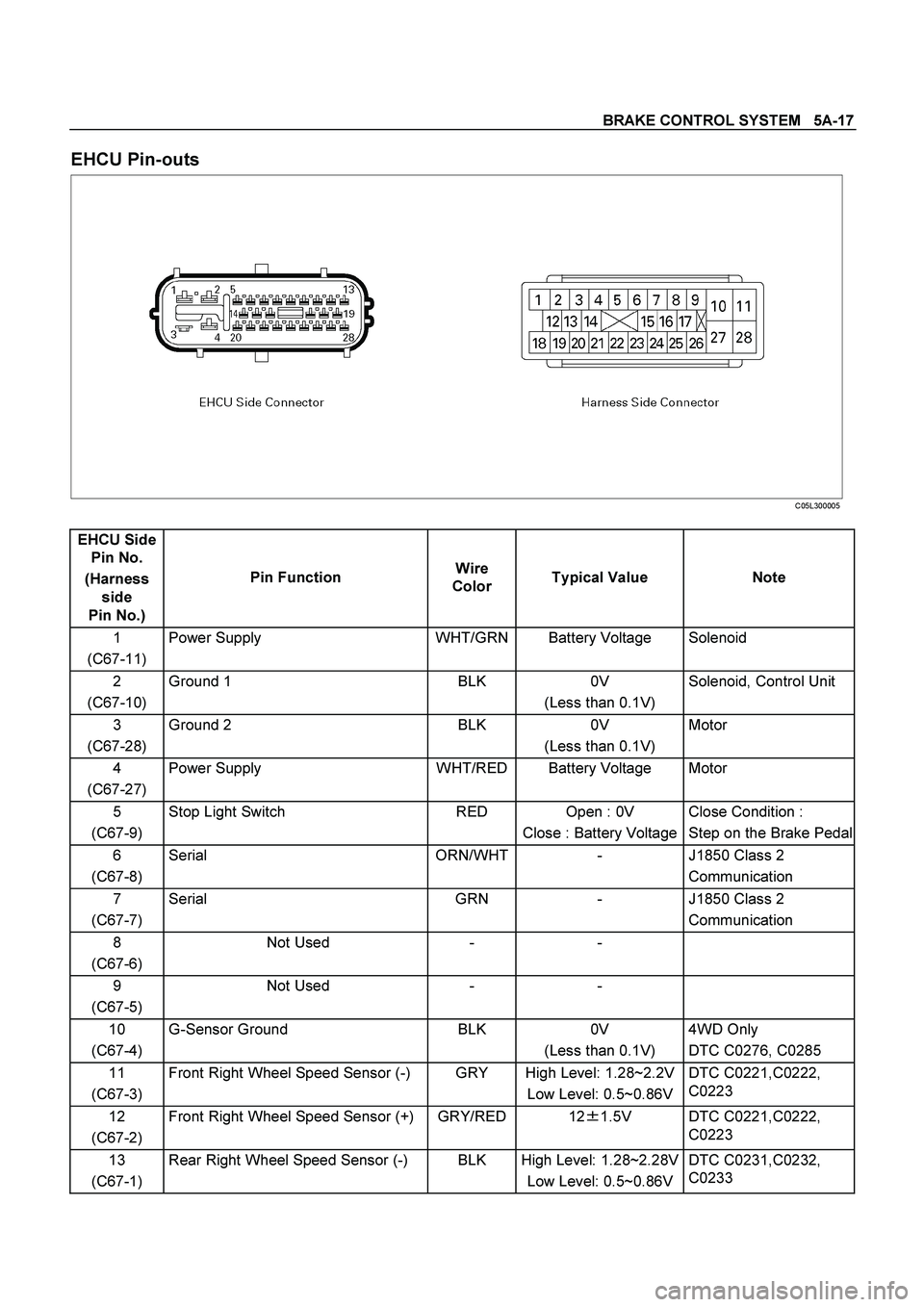
EHCU Pin-outs
C05L300005
EHCU Side
Pin No.
(Harness
side
Pin No.) Pin Function Wire
Color Typical Value Note
1
(C67-11) Power Supply WHT/GRN Battery Voltage Solenoid
2
(C67-10) Ground 1 BLK 0V
(Less than 0.1V) Solenoid, Control Unit
3
(C67-28) Ground 2 BLK 0V
(Less than 0.1V) Motor
4
(C67-27) Power Supply WHT/RED Battery Voltage Motor
5
(C67-9) Stop Light Switch RED Open : 0V
Close : Battery Voltage Close Condition :
Step on the Brake Pedal
6
(C67-8) Serial ORN/WHT - J1850 Class 2
Communication
7
(C67-7) Serial GRN - J1850 Class 2
Communication
8
(C67-6) Not Used - -
9
(C67-5) Not Used - -
10
(C67-4) G-Sensor Ground BLK 0V
(Less than 0.1V) 4WD Only
DTC C0276, C0285
11
(C67-3) Front Right Wheel Speed Sensor (-) GRY High Level: 1.28~2.2V
Low Level: 0.5~0.86V DTC C0221,C0222,
C0223
12
(C67-2) Front Right Wheel Speed Sensor (+) GRY/RED 12�
1.5V DTC C0221,C0222,
C0223
13
(C67-1) Rear Right Wheel Speed Sensor (-) BLK High Level: 1.28~2.28V
Low Level: 0.5~0.86V DTC C0231,C0232,
C0233
Page 334 of 4264

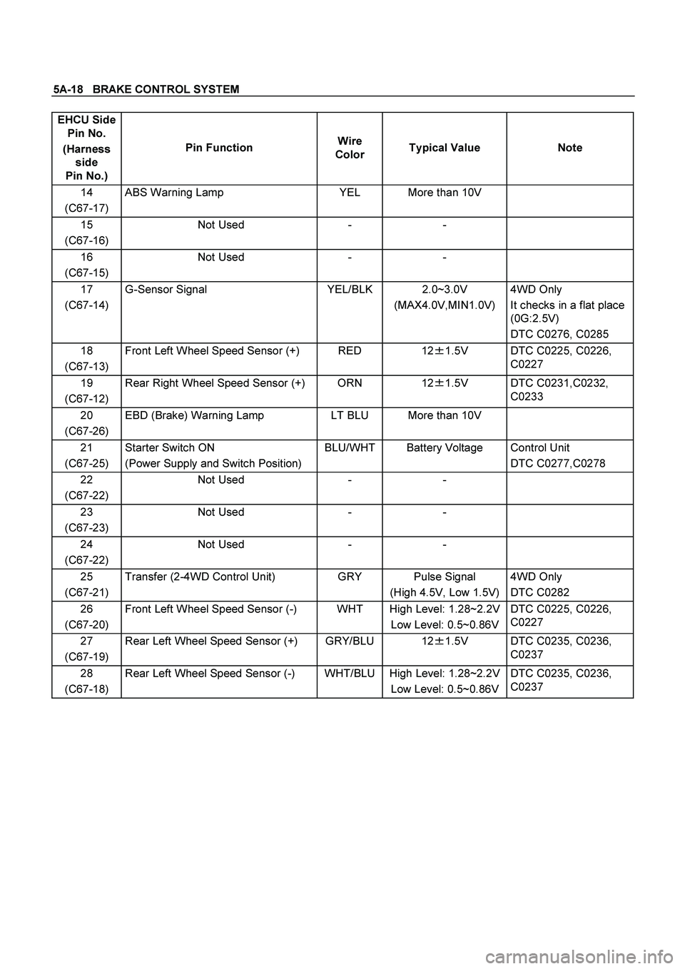
5A-18 BRAKE CONTROL SYSTEM
EHCU Side
Pin No.
(Harness
side
Pin No.) Pin Function Wire
Color Typical Value Note
14
(C67-17) ABS Warning Lamp YEL More than 10V
15
(C67-16) Not Used - -
16
(C67-15) Not Used - -
17
(C67-14) G-Sensor Signal YEL/BLK 2.0~3.0V
(MAX4.0V,MIN1.0V) 4WD Only
It checks in a flat place
(0G:2.5V)
DTC C0276, C0285
18
(C67-13) Front Left Wheel Speed Sensor (+) RED 12�
1.5V DTC C0225, C0226,
C0227
19
(C67-12) Rear Right Wheel Speed Sensor (+) ORN 12�
1.5V DTC C0231,C0232,
C0233
20
(C67-26) EBD (Brake) Warning Lamp LT BLU More than 10V
21
(C67-25) Starter Switch ON
(Power Supply and Switch Position) BLU/WHT Battery Voltage Control Unit
DTC C0277,C0278
22
(C67-22) Not Used - -
23
(C67-23) Not Used - -
24
(C67-22) Not Used - -
25
(C67-21) Transfer (2-4WD Control Unit) GRY Pulse Signal
(High 4.5V, Low 1.5V) 4WD Only
DTC C0282
26
(C67-20) Front Left Wheel Speed Sensor (-) WHT High Level: 1.28~2.2V
Low Level: 0.5~0.86V DTC C0225, C0226,
C0227
27
(C67-19) Rear Left Wheel Speed Sensor (+) GRY/BLU 12�
1.5V
DTC C0235, C0236,
C0237
28
(C67-18) Rear Left Wheel Speed Sensor (-) WHT/BLU High Level: 1.28~2.2V
Low Level: 0.5~0.86V DTC C0235, C0236,
C0237
Page 335 of 4264

BRAKE CONTROL SYSTEM 5A-19
System Components
Electronic Hydraulic Control Unit (EHCU), four Wheel
Speed Sensors, two Warning Lamps, and G-sensor.
Electronic Hydraulic Control Unit (EHCU)
The EHCU consists of ABS control circuits, fault
detector, and a fail-safe. It drives the EHCU according
to the signal from each sensor, cancelling ABS to return
to normal braking when a malfunction has occurred in
the ABS.
The EHCU has a self-diagnosing function which can
indicate faulty circuits during diagnosis.
The EHCU is mounted on the engine compartment rear
left side. It consists of a motor, solenoid valves fail safe
relay.
Solenoid Valves: Reduces or holds the caliper fluid
pressure for each front brake or both rear brakes
according to the signal sent from the EHCU.
Buffer chamber: Temporarily holds the brake fluid that
returns from the front and rear brake so that pressure
of front brake can be reduced smoothly.
Motor: Drives the pump according to the signal from
EHCU.
Fail safe Relay: When failure occurs in ABS.
The power supply to solenoid Valve is cut.
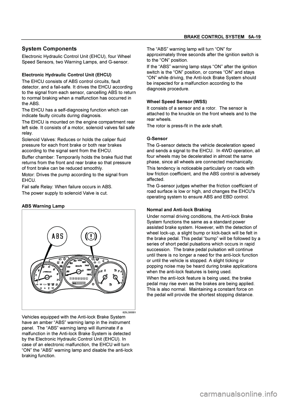
ABS Warning Lamp
825L300001
Vehicles equipped with the Anti-lock Brake System
have an amber “ABS” warning lamp in the instrument
panel. The “ABS” warning lamp will illuminate if a
malfunction in the Anti-lock Brake System is detected
by the Electronic Hydraulic Control Unit (EHCU). In
case of an electronic malfunction, the EHCU will turn
“ON” the “ABS” warning lamp and disable the anti-lock
braking function.
The “ABS” warning lamp will turn “ON” for
approximately three seconds after the ignition switch is
to the “ON” position.
If the “ABS” warning lamp stays “ON” after the ignition
switch is the “ON” position, or comes “ON” and stays
“ON” while driving, the Anti-lock Brake System should
be inspected for a malfunction according to the
diagnosis procedure.
Wheel Speed Sensor (WSS)
It consists of a sensor and a rotor. The sensor is
attached to the knuckle on the front wheels and to the
rear wheels.
The rotor is press-fit in the axle shaft.
G-Sensor
The G-sensor detects the vehicle deceleration speed
and sends a signal to the EHCU. In 4WD operation, all
four wheels may be decelerated in almost the same
phase, since all wheels are connected mechanically.
This tendency is noticeable particularly on roads with
low friction coefficient, and the ABS control is adversely
affected.
The G-sensor judges whether the friction coefficient of
road surface is low or high, and changes the EHCU's
operating system to ensure ABS and EBD control.
Normal and Anti-lock Braking
Under normal driving conditions, the Anti-lock Brake
System functions the same as a standard power
assisted brake system. However, with the detection of
wheel lock-up, a slight bump or kick-back will be felt in
the brake pedal. This pedal “bump” will be followed by a
series of short pedal pulsations which occurs in rapid
succession. The brake pedal pulsation will continue
until there is no longer a need for the anti-lock function
or until the vehicle is stopped. A slight ticking or
popping noise may be heard during brake applications
when the anti-lock features is being used.
When the anti-lock feature is being used, the brake
pedal may rise even as the brakes are being applied.
This is also normal. Maintaining a constant force on
the pedal will provide the shortest stopping distance.