Page 3981 of 4264
CONSTRUCTION AND FUNCTION 7A1-35
CONTROL CIRCUIT BLOCK DIAGRAM
Speed sensor
Turbine sensor
Brake switch
Inhibitor switch
Power drive, 3rd start
switch
ATF oil thermo sensor
High clutch oil pressure
switch
2-4 brake oil pressure
switch
Low & reverse brake oil
pressure switch
Transfer control module
(4WD Only)
Engine Control Module
(ECM)
Line pressure solenoid
Low clutch solenoid
High clutch solenoid
2-4 brake solenoid
Low & reverse brake
solenoid
Lock-up solenoid
ATF temperature
indicator lamp
Speed meter (2WD
Only)
Power, 3rd start indicator
lamp
Check trans indicator
lamp
Data link connector Self-diagnosis
function
Transmission
Control
Module
(TCM)
4L mode
Engine
speed
Throttle
angle
Figure 54. Control Circuit Block Diagram
Page 4147 of 4264
 7A2-155
No. Wire
Color Pin Name Input /
OutputConnected toMeasurement
Item Measurement
Condition StandardInspection
Point at
Trouble
Related
harness
Engine
Speed
Sensor")
DIAGNOSIS (JR405E) 7A2-155
No. Wire
Color Pin Name Input /
OutputConnected toMeasurement
Item Measurement
Condition StandardInspection
Point at
Trouble
Related
harness
Engine
Speed
Sensor A7 BLK/
RED Engine Speed Sensor Input ECM Voltage (Wave
form) At 2000rpm.
Circuit tester
(+) to A7 pin,
(-) to B5 pin. Pulse
generated (At
AC range
approx. 6.2V)
ECM
A8 - - - - - - - -
A9 - - - - - - - -
Related
harness
Speed
sensor
Speed meter
A10 BLK/
YEL Vehicle Speed Sensor Out (2WD Only) Output Speed meter Voltage (Wave
form) At run in L
range in 1st
gear 20 km/h.
Circuit tester
(+) to A10 pin,
(-) to B5 pin. Pulse
generated (At
AC range
approx. 6.5V)
TCM
At switch
pushed Less than 2VRelated
harness
A11 GRN/
WHT 3rd Start Select Switch Input 3rd start switch Voltage
At switch off 10 – 14.5V 3rd start
switch
At 4L Less than 2VRelated
harness
A12 BLU/
WHT 4L Mode Switch (4WD Only) InputTransfer control
unit Voltage
At other than
4L 10 – 14.5V 4L switch
A13 - - - - - - - -
A14 - - - - - - - -
A15 - - - - - - - -
At fully close Off duty 10%Related
harness
ECM A16 RED/
WHT Throttle Position Sensor Input ECM Wave form
(140Hz Duty
signal) *1
At fully open Off duty 90%Throttle
position
sensor
At 3 range 10 – 14.5V Related
harness
A17 BLK/
GRN 3 Range Switch Input Inhibitor switch Voltage
At other than
3 range Less than 2VInhibitor
switch
At key switch
ON 10 – 14.5V Related
harness
A18 YEL/
BLK DIAG Switch InputData link
connector Voltage
At short circuit
of DIAG
switch Less than 2VRelated
harness
At lamp OFF 10 – 14.5V Related
harness A19 ORG/
BLU A/T OIL TEMP Indicator Lamp OutputAT OIL TEMP
indicator lamp Voltage
At lamp ON Less than 2V Lamp
At lamp OFF 10 – 14.5V Related
harness A20 GRN/
YEL CHECK TRANS Indicator Lamp OutputCHECK TRANS
indicator Lamp Voltage
At lamp ON Less than 2V Lamp
At lamp OFF 10 – 14.5V Related
harness A21 PNK POWER DRIVE Indicator Lamp OutputPOWER DRIVE
indicator lamp Voltage
At lamp ON Less than 2V Lamp
A22 - - - - - - - -
A23 - - - - - - - -
Page 4182 of 4264
7A4-8 UNIT REPAIR (JR405E)
25ASSY019
�
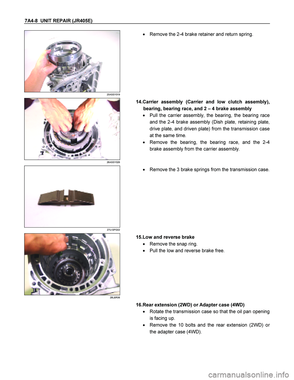
Remove the 2-4 brake retainer and return spring.
26ASSY026
14.Carrier assembly (Carrier and low clutch assembly),
bearing, bearing race, and 2 – 4 brake assembly
� Pull the carrier assembly, the bearing, the bearing race
and the 2-4 brake assembly (Dish plate, retaining plate,
drive plate, and driven plate) from the transmission case
at the same time.
� Remove the bearing, the bearing race, and the 2-4
brake assembly from the carrier assembly.
27U-SPG02
�
Remove the 3 brake springs from the transmission case.
28L&R06
15.Low and reverse brake
� Remove the snap ring.
� Pull the low and reverse brake free.
16.Rear extension (2WD) or Adapter case (4WD)
� Rotate the transmission case so that the oil pan opening
is facing up.
� Remove the 10 bolts and the rear extension (2WD) o
r
the adapter case (4WD).
Page 4254 of 4264
7A4-80 UNIT REPAIR (JR405E)
40ASSY091
�
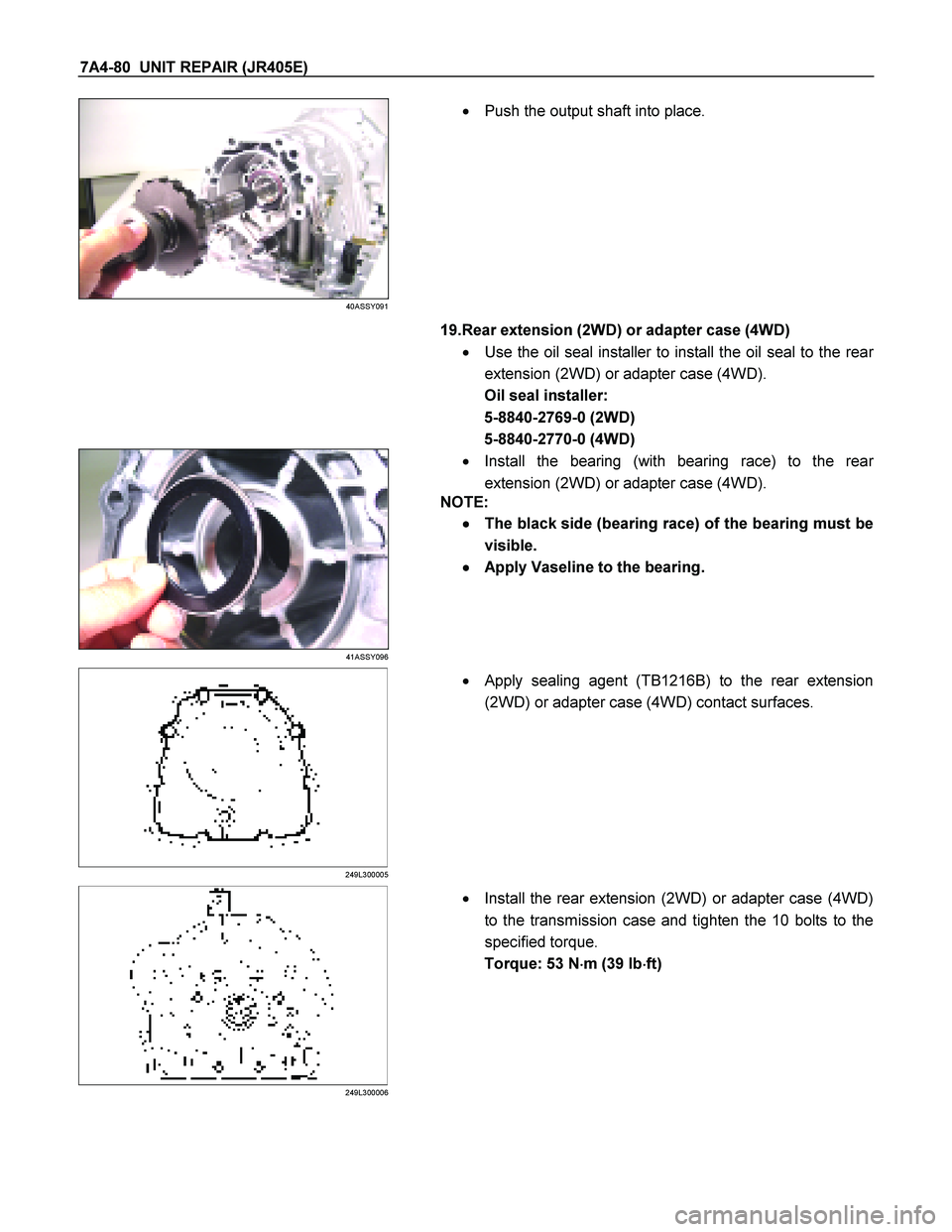
Push the output shaft into place.
19.Rear extension (2WD) or adapter case (4WD)
� Use the oil seal installer to install the oil seal to the rea
r
extension (2WD) or adapter case (4WD).
Oil seal installer:
5-8840-2769-0 (2WD)
5-8840-2770-0 (4WD)
41ASSY096
�
Install the bearing (with bearing race) to the rear
extension (2WD) or adapter case (4WD).
NOTE:
�
� �
�
The black side (bearing race) of the bearing must be
visible.
�
� �
�
Apply Vaseline to the bearing.
249L300005
�
Apply sealing agent (TB1216B) to the rear extension
(2WD) or adapter case (4WD) contact surfaces.
249L300006
� Install the rear extension (2WD) or adapter case (4WD)
to the transmission case and tighten the 10 bolts to the
specified torque.
Torque: 53 N �
��
�
m (39 Ib �
��
�
ft)