Page 3804 of 4264
7A3-48 ON-VEHICLE SERVICE (AW30 –40LE)
11. Install the suspension crossmember.
Torque: 65 N �
��
�
m (6.6 kg �
��
�
m/48 lb ft)
12. Install filler tube and insert oil level gage.
Torque: 22 N �
��
�
m (2.2 kg �
��
�
m/16 lb ft)
13. Install select cable by connecting inner cable to
select lever and installing outer cable with bracket.
14. Install the fuel pipe brackets to the transmission. Install the fuel pipe clips with the pipes to the
bracket.
P1010010
15. Connect the transmission harness connectors and
clips.
16. Connect transmission oil cooler pipes to A/T.
Torque: 44 N �
��
�
m (4.5 kg
�
��
�
m/33 lb ft)
17. Install oil cooler pipe clamp and bracket to the
converter housing.
18.Tighten oil cooler pipe clamp bolt at the engine
mount side.
P1010024
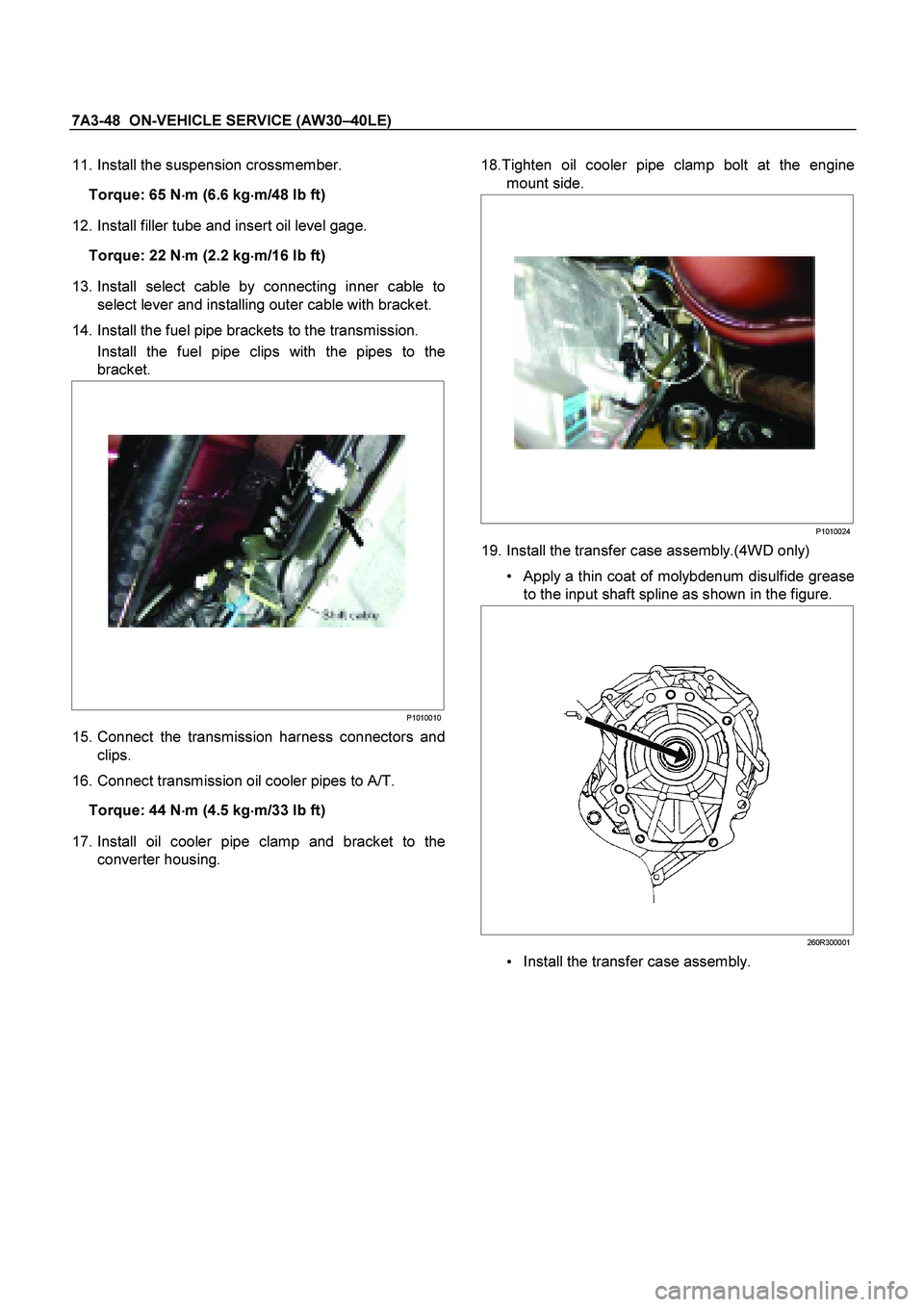
19. Install the transfer case assembly.(4WD only)
Apply a thin coat of molybdenum disulfide grease
to the input shaft spline as shown in the figure.
260R300001
Install the transfer case assembly.
Page 3805 of 4264
ON-VEHICLE SERVICE (AW30 –40LE) 7A3-49
Tighten transmission transfer bolts as shown in
the figure.(4WD only)
261R300002
20. Connect transfer harness connectors and
clips.(4WD only)
Speed sensor
2W-4W shift actuator
21. Install the middle exhaust pipe.
RTW37ASH0001
22. Install the rear propeller shaft.
Torque: 63 N �
��
�
m (6.4 kg �
��
�
m/46 lb ft)
NOTE: Align alignment marks on the flange.
23. Install the center bearing on crossmember.
Torque: 69 N �
��
�
m (7.0 kg �
��
�
m/51 lb ft)
24.Install the front propeller shaft.(4WD only)
Torque: 63 N �
��
�
m (6.4 kg �
��
�
m/46 lb ft)
NOTE: Align alignment marks on the flange.
401RS023
25. Connect battery ground cable.
Page 3949 of 4264

CONSTRUCTION AND FUNCTION 7A1-3
DESCRIPTION
CONSTRUCTION
1 Converter Housing 6 Low Clutch 11 Oil Pump
2 Torque Converter 7 Low & Reverse Brake 12 Control Valve
3 High Clutch 8 Output Shaft 13 Low One-way Clutch
4 Reverse Clutch 9 Extension Housing 14 Parking Gear
5 2-4 Brake 10 Input Shaft
Figure 1. Construction of Automatic Transmission
The JR405E automatic transmission is electrically controlled by a microcomputer transmission control module
(TCM). There are four forward speeds and one reverse speed.
This JR405E automatic transmission employs a clutch pressure direct control system (Direct Electronic Shift
Control: DESC) using a duty cycle type solenoid, which ensures high shift quality.
This transmission also controls learning and constantly checks the time of each clutch and brake required for
the speed change to match this time with the target value for the optimum speed change.
The TCM will automatically select the most appropriate shift points and lock-up points depending on the
throttle opening angle, the vehicle speed and the vehicle load.
If any trouble arises in the vehicle sensor, throttle sensor, solenoid, etc., the fail-safe control function is
activated to keep the running performance.
Problems with the sensors, the solenoids can be quickly detected with the self diagnosis procedure described
in this manual.
The JR405E automatic transmission consists of the torque converter, the oil pump, the input shaft, the out put
shaft, the planetary gears and the control valve.
The gear train consists of two planetary gear sets and three multiple plate clutches in combination with two
multiple plate brakes and a one-way clutch.
2WD
4WD
Page 3951 of 4264
CONSTRUCTION AND FUNCTION 7A1-5
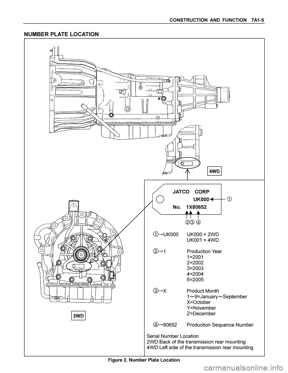
NUMBER PLATE LOCATION
JATCO CORP
���
������ ��� UK000�
�� �
���
������ ���1
No. 1X80652����
�������� ����
23 4
1�UK000 UK000 = 2WD
UK001 = 4WD
2�1 Production Year
1=2001
2=2002
3=2003
4=2004
5=2005
3�X Product Month
1�9=January�September
X=October
Y=November
Z=December
4�80652 Production Sequence Number
Serial Number Location
2WD:Back of the transmission rear mounting
4WD:Left side of the transmission rear mounting
Figure 2. Number Plate Location
4WD
2WD
Page 3952 of 4264
7A1-6 CONSTRUCTION AND FUNCTION
ELECTRONIC CONTROL COMPONENTS LOCATION
4WD Only 4WD Only
Instrument panel (Meter)
Speed meter (2WD Only)
Shift position indicator lamp
POWER DRIVE, 3rd START
indicator lamp
A/T OIL TEMP indicator lamp
CHECK TRANS indicator lam
p
Brake pedal
Brake Switch
Select lever
Power Drive
, 3rd Start select switch
Transmission Control Module (TCM)
Electrical source
Ignition
Battery voltage
Speed sensor
Turbine sensor
Inhibitor switch
ATF thermo sensor
High clutch oil pressure switch
2-4 brake oil pressure switch
Low & Reverse brake oil pressure
switch
Line pressure solenoid
Low clutch solenoid
High clutch solenoid
2-4 brake solenoid
Low & Reverse brake solenoid
Lock-up solenoid
Transmission
Transfer Control Module
Transfer
4L mode switch
Engine
Engine speed sensor
Throttle Position Sensor
Engine Control Module (ECM)
Data link connector
Page 3971 of 4264

� The TCM is fitted side of brake pedal by means of two stud bolts.
� The TCM judges necessary line pressure, gear shifting point")
CONSTRUCTION AND FUNCTION 7A1-25
TRANSMISSION CONTROL MODULE (TCM)
� The TCM is fitted side of brake pedal by means of two stud bolts.
� The TCM judges necessary line pressure, gear shifting point and lock-up operation based on electrical
signals from switches and sensors and sends appropriate signals to solenoids.
�� �� �� �� �� �� �� � �
�� �� �� �� �� �� �� � �
�
� �
� �
� �
� �
� �
� �
�
�
� �
� �
� �
� �
� �
� �
� �
�
�
�
� � � � � �
� � �
� � � � � � �
� � �
�
Connect to White Connector Connect to Grey Connector
Figure 49. Pin Assignment
Pin No. Pin Assignment Pin No.Pin Assignment
B1 2-4 Brake Oil Pressure Switch A1 V BATT (Battery Back-up Power Supply)
B2 2 Range Switch A2 P Range Switch
B3 Turbine Sensor A3 Brake Switch
B4 ATF Thermo Sensor A4 3rd Start Indicator Lamp
B5 Ground A5 K-Line Signal (Tech 2 Serial Communication)
B6 Low & Reverse Brake Duty Solenoid A6 No Connection
B7 2-4 Brake Duty Solenoid A7 Engine Speed Sensor
B8 High Clutch Duty Solenoid A8 No Connection
B9 Low Clutch Duty Solenoid A9 No Connection
B10 N Range Switch A10 Vehicle Speed Sensor Out (2WD Only)
B11 D Range Switch A11 3rd START Select Switch
B12 Low & Reverse Brake Oil Pressure Switch A12 4L Mode Switch (4WD Only)
B13 Vehicle Speed Sensor A13 No Connection
B14 ATF Thermo Sensor Ground A14 No Connection
B15 Ground A15 No Connection
B16 No Connection A16 Throttle Position Sensor
B17 Lock-up Duty Solenoid A17 3 Range Switch
B18 Vign �Ignition Power Supply) A18 DIAG Switch (Test Switch)
B19 R Range Switch A19 A/T OIL TEMP Indicator Lamp
B20 High Clutch Oil Pressure Switch A20 CHECK TRANS Indicator Lamp
B21 L Range Switch A21 POWER DRIVE Indicator Lamp
B22 Ground (Shift Solenoid) A22 No Connection
B23 Line Pressure Solenoid A23 No Connection
B24 Vign (Ignition Power Supply) A24 POWER DRIVE Select Switch
Page 3975 of 4264
CONSTRUCTION AND FUNCTION 7A1-29
CONTROL ITEM, INPUT AND OUTPUT
Control item
Item
Line
pressure
control
Gear
shift
control
Shift
pattern
selection
Lock-up
controlDirect
electronic
shift
control
(DECS)
Learning
control
Fail-safe
function
Self-
diagnosis
function
Speed sensor
Turbine sensor
Engine speed sensor
Brake switch
Inhibitor switch
Mode select switch
4L switch (4WD Only)
ATF thermo sensor
High clutch oil pressure switch
2-4 brake oil pressure switch
Low & Reverse brake oil pressure
switch
Input
Throttle position sensor
Line pressure solenoid
Low clutch solenoid
High clutch solenoid
2-4 brake solenoid
Low & Reverse brake solenoid
Lock-up solenoid
Shift pattern indicator lamp
ATF temperature indicator lamp
Output
Check trans indicator lamp
Page 3980 of 4264

7A1-34 CONSTRUCTION AND FUNCTION
MAJOR INPUT/OUTPUT COMPONENT AND THEIR FUNCTIONS
Speed sensor Detects output shaft revolution and sends rpm signal to TCM.
Turbine sensor Detects input shaft revolution and sends rpm signal to TCM.
Engine speed sensor Inputs engine revolution from engine control computer.
Brake switch Detects brake pedal operated by the driver and sends signal to
TCM.
Inhibitor switch Detects select lever position and sends signal to TCM.
Mode select switch Detects "Power Drive" or "3rd Start" selected by the driver and
sends signal to TCM.
4L switch (4WD Only) Inputs 4L mode from transfer control computer.
ATF thermo sensor Detects ATF temperature and sends signal to TCM.
High clutch oil pressure switch Detects high clutch supply oil pressure and sends signal to
TCM.
2-4 brake oil pressure switch Detects 2-4 brake supply oil pressure and sends signal to
TCM.
Low & Reverse brake oil pressure switch Detects low & reverse brake supply oil pressure and signal to
TCM.
Throttle position sensor Inputs throttle opening angle from engine control computer.
Input
TCM Judges necessary line pressure, gear shifting point and lock-up
operation based on electrical signals from switches and
sensors and sends appropriate signals to solenoids.
Line pressure solenoid Regulates oil pump delivery pressure to the appropriate line
pressure for current driving condition based on signal from
TCM.
Low clutch solenoid Selects appropriate gear shifting position for current driving
condition and regulates low clutch supply oil pressure based on
signal from TCM.
High clutch solenoid Selects appropriate gear shifting position for current driving
condition and regulates high clutch supply oil pressure based
on signal from TCM.
2-4 brake solenoid Selects appropriate gear shifting position for current driving
condition and regulates 2-4 brake supply oil pressure based on
signal from TCM.
Low & Reverse brake solenoid Selects appropriate gear shifting position for current driving
condition and regulates low & reverse brake supply oil
pressure based on signal from TCM.
Lock-up solenoid Regulates lock-up pressure to appropriate level for current
driving conditions based on signal from TCM.
Mode indicator lamp Indicates POWER DRIVE or 3rd START switch position.
Speed meter signal (2WD Only) Outputs vehicle speed to speed meter.
A/T OIL TEMP indicator lamp Indicates A/T OIL TEMP indicator lamp in case of high
temperature.
Output
CHECK TRANS indicator lamp Indicates CHECK TRANS indicator lamp in case of
malfunction.
 7A3-49
Tighten transmission transfer bolts as shown in
the figure.(4WD only)
261R300002
20. Connect transfer harness connectors and
clips.(4WD only)")

Speed meter (2WD Only)
Shift position indicator lamp
POW")
