Page 150 of 4264
4A-14 PROPELLER SHAFT
INSPECTION AND REPAIR
Make all necessary adjustment, repairs, and part replacements if wear, damage, or other problems are discovered
during inspection.
Visual Check
Inspect following parts for wear, damage, or other abnormal
conditions.
Spider
Needle roller bearing
Yoke
Flange
Center bearing
Cushioning rubber
Bracket
401RS007
Outside Diameter of Spider Pins
mm(in)
Standard Limit
17 (0.67) 16.99 (0.669)
Page 160 of 4264
4A-24 PROPELLER SHAFT
401RS028
1. Apply alignment marks (1) on the yokes of the universal
joint, then remove snap ring.
401RS006
2. Tap out the needle roller bearing by gently striking the
shoulder of the yoke, using a mallet or a copper hammer.
3. Make sure of proper position for reinstallation by applying
setting marks, then remove spider.
Inspection and Repair
Make necessary correction or parts replacement if wear,
damage, corrosion or any other abnormal condition is found
through inspection.
NOTE:
When any part of the journal assembly (spider, needle rolle
r
bearing) requires replacement, be sure to replace the entire
assembly.
Check the following parts for wear, damage, noise or any othe
r
abnormal conditions:
1. Spider
2. Needle roller bearing
3. Yoke
4. Flange
5. Constant velocity joint
401RS007
Outside Diameter of Spider Pin
Standard: 17.00 mm (0.669 in)
Limit: 16.90 mm (0.665 in)
Page 177 of 4264
REAR AXLE 4B-13
INSPECTION AND REPAIR
Make all necessary adjustments, repairs, and part
replacements if wear, damage, or other problems are
discovered during inspections.
Visual Check
Inspect the following parts for wear, damage or other
abnormal conditions.
�
Axle Shaft
Axle Shaft
When checking the axle shaft, pay special attention to
the splined portions and replace the shaft if distortion
or step wear is noticeable. Correct slight step wear
with a pencil grinder.
420RS008
Axle Shaft Run-Out
Check the shafts for bending with the use of a dial
indicator in contact with the shaft. Rotate the shaft
slowly and observe the dial indicator.
Limit mm(in
)
1.0 (0.039)
Note :
Never use heat to correct bending.
420RY 00019
Axle Shaft Flange Run-Out
Check the axle shaft flange for run-out. Hold the
probe of a dial indicator in contact with the flange.
Rotate the shaft slowly and observe the dial.
Limit mm(in
)
0.08 (0.003)
420RY 00018
Page 197 of 4264
REAR AXLE 4B-33
Disassembly
1. Remove bolt.
2. Remove ring gear.
3. Drive out lock pin using a long drift Punch.
425RS042
4. Check the amount of backlash between pinion
gear on side gear before removal of cross pin.
Backlash :
0.13-0.18 mm (0.005–0.007 in)
5. Remove the cross pin by using a brass drift
punch and hammer.
425RS043
6. Take out pinion gear, side gear and thrust
washer.
Inspection and Repair
Make necessary correction or parts replacement if
wear, damage, corrosion or any other abnormal
conditions are found through inspection.
Check the following parts:
�
Ring gear, pinion gear
�
Bearing
�
Side gear, pinion gear, cross pin
�
Differential cage, carrier
�
Thrust washer
�
Oil seal
Clearance between pinion gear and cross pin:
mm(in)
Standard Limit
0.06 - 0.12
(0.002 - 0.005) 0.2 (0.008)
425L100012
Clearance between side gear and differential cage.
mm(in)
Standard Limit
0.05 - 0.11
(0.002 - 0.004) 0.15 (0.006)
Page 202 of 4264

4B-38 REAR AXLE
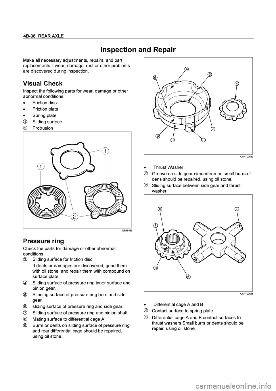
Inspection and Repair
Make all necessary adjustments, repairs, and part
replacements if wear, damage, rust or other problems
are discovered during inspection.
Visual Check
Inspect the following parts for wear, damage or other
abnormal conditions.
�
Friction disc
�
Friction plate
�
Spring plate
1 Sliding surface
2 Protrusion
425RS056
Pressure ring
Check the parts for damage or other abnormal
conditions.
3 Sliding surface for friction disc
If dents or damages are discovered, grind them
with oil stone, and repair them with compound on
surface plate.
4 Sliding surface of pressure ring inner surface and
pinion gear.
5 Slinding surface of pressure ring bore and side
gear.
6 sliding surface of pressure ring and side gear.
7 Sliding surface of pressure ring and pinion shaft.
8 Mating surface to differential cage A.
9 Burrs or dents on sliding surface of pressure ring
and rear differential cage should be repaired,
using oil stone.
425RY00022
�
Thrust Washer
10 Groove on side gear circumference small burrs of
dens should be repaired, using oil stone.
11 Sliding surface between side gear and thrust
washer.
425RY00024
�
Differential cage A and B
12 Contact surface to spring plate
13 Differential cage A and B contact surfaces to
thrust washers Small burrs or dents should be
repair, using oil stone.
Page 240 of 4264
4C1-20 FRONT WHEEL DRIVE
6. Using snap ring pliers, remove the snap ring (1) fastening
the ball retainer to the center shaft.
7. Remove ball retainer, ball guide and bellows.
8. Use a hammer and chisel to remove the 3 pawls (above
the large and small boot bands on the UJ side).
CAUTION :
Take care not to damage the bellows during band removal.
9. Remove band (1).
10. Remove bellows.
11. Remove dust seal from UJ.
12. Remove UJ shaft assembly.
13. Remove the mounting bracket fixing bolts, and then
remove DOJ case assembly from the axle case.
14. Remove snap ring and bearing.
15. Remove snap ring and oil seal.
16. Remove bracket.
Inspection And Repair
Make necessary correction or parts replacement if wear,
damage, corrosion or any other abnormal condition are found
through inspection.
Check the following parts.
1. Drive shaft joint assembly
2. DOJ case, ball, ball guide, ball retainer
3. Bellows
4. Bearing
5. Dust seal, oil seal
Page 249 of 4264

FRONT WHEEL DRIVE 4C1-29
INSPECTION AND REPAIR
Make all necessary adjustments, repairs, and part replacements if wear, damage, or other problems are discovered
during inspection.
� Ring gear, pinion gear
� Bearing
�
Side gear, pinion gear, cross pin
�
Differential cage, carrier
�
Thrust washer
�
Oil seal
Visual Check
Inspect the following parts for wear, damage, or other
abnormal conditions.
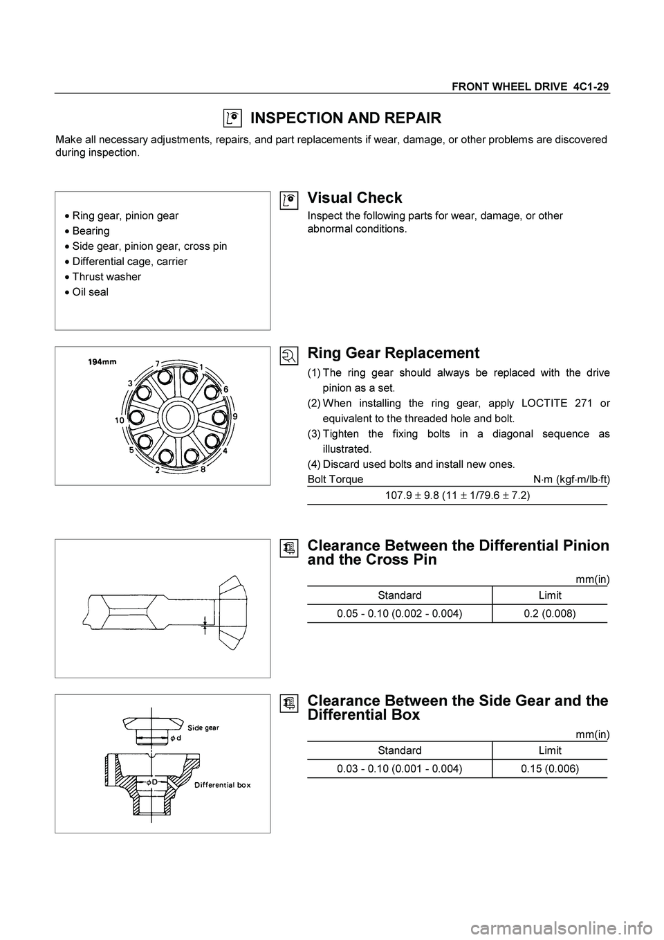
Ring Gear Replacement
(1) The ring gear should always be replaced with the drive
pinion as a set.
(2) When installing the ring gear, apply LOCTITE 271 o
r
equivalent to the threaded hole and bolt.
(3) Tighten the fixing bolts in a diagonal sequence as
illustrated.
(4) Discard used bolts and install new ones.
Bolt Torque N�m (kgf�m/lb�ft)
107.9 � 9.8 (11 � 1/79.6 � 7.2)
Clearance Between the Differential Pinion
and the Cross Pin
mm(in)
Standard Limit
0.05 - 0.10 (0.002 - 0.004) 0.2 (0.008)
Clearance Between the Side Gear and the
Differential Box
mm(in)
Standard Limit
0.03 - 0.10 (0.001 - 0.004) 0.15 (0.006)
Page 265 of 4264
FRONT WHEEL DRIVE 4C1-45
INSPECTION AND REPAIR
Make necessary correction or parts replacement if wear, damage or any other abnormal conditions are found
through inspection.
For inspection and servicing of disc caliper, and relative parts, and ABS parts, refer to section 5 Brakes.
� Hub
� Hub bearing
� Bearing outer race
�
Disc
�
Oil seal
�
Knuckle spindle
�
ABS sensor rotor
�
Caliper
Visual Check
Check the following parts for wear, damage or other abnormal
conditions.