Page 3046 of 4264

This illustration is based on RHD model RTW410LF000501
Removal Steps
1. Radiator grille
2. Fr")
1-36 HEATER AND AIR CONDITIONING
CONDENSER
REMOVAL AND INSTALLATION (4JA1-TC, 4JH1-TC)
This illustration is based on RHD model RTW410LF000501
Removal Steps
1. Radiator grille
2. Front bumper fascia
�
Refer to SECTION 2A “FRONT
BUMPER”
3. Front bumper inpact support assembly
�
Refer to SECTION 2A “FRONT
BUMPER”
4. Air cleaner assembly
5. Inter cooler
�
Refer to SECTION 6A “INTER COOLER”
6. Engine hood lock
7. Engine hood front end stay
8. Pressure switch connector
9. Condenser fan connector
10. Refrigerant line
11. Refrigerant line
12. Receiver/drier bracket
13. Receiver/drier
14. Condenser assembly
Installation Steps
14. Condenser assembly
13. Receiver/drier
12. Receiver/drier bracket
11. Refrigerant line
10. Refrigerant line
9. Condenser fan connector
8. Pressure switch connector
7. Engine hood front end stay
6. Engine hood lock
5. Inter cooler
�
Refer to SECTION 6A “INTER COOLER”
4. Air cleaner assembly
3. Front bumper inpact support assembly
�
Refer to SECTION 2A “FRONT
BUMPER”
2. Front bumper fascia
�
Refer to SECTION 2A “FRONT
BUMPER”
1. Radiator grille
Page 3047 of 4264
HEATER AND AIR CONDITIONING 1-37
REMOVAL AND INSTALLATION (EXCEPT 4JA1-TC, 4JH1-TC)
RTW410LF000701
Removal Steps
1. Radiator grille
2. Engine hood lock
3. Engine hood front end stay
4. Pressure switch connector
5. Condenser fan connector
6. Refrigerant line
7. Refrigerant line
8. Receiver/drier bracket
9. Receiver/drier
10. Condenser assembly
Installation Steps
10. Condenser assembly
9. Receiver/drier
8. Receiver/drier bracket
7. Refrigerant line
6. Refrigerant line
5. Condenser fan connector
4. Pressure switch connector
3. Engine hood front end stay
2. Engine hood lock
1. Radiator grille
Page 3049 of 4264
HEATER AND AIR CONDITIONING 1-39
RECEIVER / DRIER
REMOVAL AND INSTALLATION
RTW410LF000601
Removal Steps
1. Radiator grille
2. Trinary pressure switch connector
3. Refrigerant line
4. Bracket bolt
5. Receiver/drier
Installation Steps
5. Receiver/drier
4. Bracket bolt
3. Refrigerant line
2. Trinary pressure switch connector
1. Radiator grille
Page 3059 of 4264

HEATER AND AIR CONDITIONING 1-49
OIL RETURN OPERATION
There is close affinity between the oil and the refrigerant.
During normal operation, part of the oil recirculates with the
refrigerant in the system.
When checking the amount of oil in the system, or replacing
any component of the system, the compressor must be run in
advance for oil return operation. The procedure is as follows:
1) Open the all doors and engine hood.
2) Start the engine and A/C switch is "ON" and Set the fan
control knob at its highest position.
3) Run the compressor for more than 20 minutes between
800 and 1,000 rpm in order to operate the system.
4) Stop the engine.
REPLACEMENT OF COMPONENT PARTS
When replacing system component parts, supply the following
amount of oil to the component parts to be installed.
Component parts to be installed Amount of oil
Evaporator 50 cm3 (1.7 fl.oz.)
Condenser 30 cm3 (1.0 fl.oz.)
Receiver/drier 30 cm3 (1.0 fl.oz.)
Refrigerant line (One piece) 10 cm3 (0.3 fl.oz.)
Refrigeration oil must be replenished if more than two parts
are removed at the same time. After installing these
components, check compressor oil.
Page 3080 of 4264
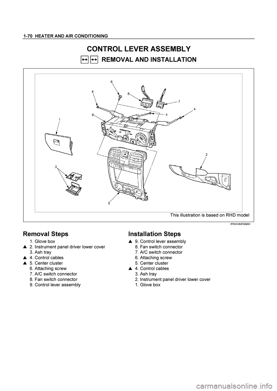
1-70 HEATER AND AIR CONDITIONING
CONTROL LEVER ASSEMBLY
REMOVAL AND INSTALLATION
This illustration is based on RHD model
RTW310MF000601
Removal Steps
1. Glove box
� 2. Instrument panel driver lower cover
3. Ash tray
� 4. Control cables
� 5. Center cluster
6. Attaching screw
7. A/C switch connector
8. Fan switch connector
9. Control lever assembly
Installation Steps
�
9. Control lever assembly
8. Fan switch connector
7. A/C switch connector
6. Attaching screw
5. Center cluster
� 4. Control cables
3. Ash tray
2. Instrument panel driver lower cover
1. Glove box
Page 3087 of 4264
HEATER AND AIR CONDITIONING 1-77
D08R300070
Fan switch and Circuit board
Check for continuity between fan switch and A/C switch side
connector terminals.
B-13 B-57
Terminal
No.
SW.
position
1 2 3 4 5 6 2 3 10 11
OFF
1
2
3
(FAN SW.)
4
OFF CIRCUIT
BOARD
(A/C SW.)
ON
Electronic Thermostat
Check for continuity between electronic thermostat side
connector terminals.
(Cooler)
RTW410SH000201
(A/C)
Page 3088 of 4264
1-78 HEATER AND AIR CONDITIONING
RTW4A0SH000201
Pressure switch
Disconnect pressure switch connector and check for continuity
between pressure switch side connector terminal.
825r300045
Heater and thermo switch relay.
Check for continuity between the relay terminals.
1 - 5 �����
No continuity
(When battery voltage is applied between 2 - 4 )
1 - 5 �����
Continuity
825r300023
Check for continuity between the relay terminals.
1 - 2 �����
No continuity
(When battery voltage is applied between 3 - 4 )
1 - 2 �����
Continuity
Page 3089 of 4264
HEATER AND AIR CONDITIONING 1-79
TROUBLESHOOTING
FAN CONTROL KNOB (FAN SWITCH)
Current flows to the blower motor through the Heater & A/C relay (X-11) to activate the rotation of the blower motor
by turning “ON” the fan control knob (fan switch). Blower motor speed is controlled in stages by the resistor, by
operating the switch from “LOW” to “HIGH.”
D08R300046-X2

RTW410LF000701
Removal Steps
1. Radiator grille
2. Engine hood lock
3. Engine hood fron")


Current flows to the blower motor through the Heater & A/C relay (X-11) to activate the rotation of the blower motor")