Page 2876 of 4264
6G-4 ENGINE LUBRICATION
Oil Pump
Oil Pump and Associated Parts
Legend
1 Oil Pump Assembly
2 Oil Pressure Switch3 Gasket
4 Sleeve
Disassembly
1. Remove crankshaft timing pulley.
2. Remove oil pan.
3. Remove oil strainer.
4. Remove oil pump assembly.
5. Remove oil pressure switch.
6. Remove gasket.
7. Remove sleeve.
Page 2877 of 4264
ENGINE LUBRICATION 6G-5
Inspection and Repair
CAUTION: Make necessary correction or parts
replacement if wear, damage or any other abnormal
conditions are found through inspection.
Body and Gears
The pump assembly must be replaced if one or more of the
conditions below is discovered during inspection:
Indentation of gear pair - Use feeler strip and straight edge.
Dimension: 0.03 mm to 0.10 mm
(0.0012 to 0.0039 in)
Oil Strainer
Check the oil strainer for cracking and scoring. If cracking and
scoring are found, the oil strainer must be replaced.
Reassembly
1. Install oil pressure switch to the oil pump.
Torque: 40 N�
�� �m (4.1 kgf�
�� �m)
2. Install the oil pump with the sleeve and the gasket.
Torque: 6 N�
�� �m (0.6 kgf�
�� �m)
3. Install oil strainer.
Torque: 8 N�
�� �m (0.8 kgf�
�� �m)
4. Install the oil pan.
Tighten the bolts:
15 N�
�� �m (1.5 kgf�
�� �m)
5. Install crankshaft timing pulley.
Tighten the bolts:
20 N�
�� �m (2.0 kgf�
�� �m)
Page 2878 of 4264
6G-6 ENGINE LUBRICATION
Oil Pan
Oil Pan and Associated Parts
(2.4L 4 ×4 Model)
(2.4L 4 ×2 Model)
Important
Disassembly
1. Loosen a drain plug to drain oil.
2. Remove engine hood.
3. Remove engine rear mounting.
4. Remove transmission assembly.
5. Remove engine front mounting.
6. Raise the vehicle and support with switch stands, and then remove engine.
7. Remove oil pan.
Page 3013 of 4264
HEATER AND AIR CONDITIONING 1-3
GENERAL DESCRIPTION
SYSTEM COOLING LINE
1.
Compressor 8.
Evaporator core
2.
Magnetic clutch 9.
Blower motor
3.
Receiver/Drier 10.
Heater unit
4.
Dual pressure switch or Trinary 11.
Mode (DEF/FOOT) control door
pressure switch (4J�
-TC, 6VE1, 12.
Mode (VENT) control door
C24SE) 13.
Electronic thermostat
5.
Condenser 14.
Heater core
6.
Evaporator assembly
7.
Expansion valve
RTW310LF001001
Page 3025 of 4264

HEATER AND AIR CONDITIONING 1-15
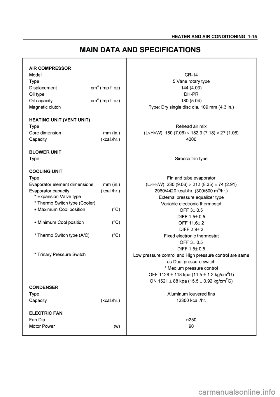
MAIN DATA AND SPECIFICATIONS
AIR COMPRESSOR
Model CR-14
Type 5 Vane rotary type
Displacement cm3 (lmp fl oz) 144 (4.03)
Oil type DH-PR
Oil capacity cm3 (lmp fl oz) 180 (5.04)
Magnetic clutch Type: Dry single disc dia. 109 mm (4.3 in.)
HEATING UNIT (VENT UNIT)
Type Rehead air mix
Core dimension mm (in.) (L�
H�
W) 180 (7.06) �
182.3 (7.18) �
27 (1.06)
Capacity (kcal./hr.) 4200
BLOWER UNIT
Type Sirocco fan type
COOLING UNIT
Type Fin and tube evaporator
Evaporator element dimensions mm (in.) (L�
H�
W) 230 (9.06) �
212 (8.35) �
74 (2.91)
Evaporator capacity (kcal./hr.) 2960/4420 kcal./hr. (300/500 m3/hr.)
* Expansion Valve type
External pressure equalizer type
* Thermo Switch type (Cooler)
Variable electronic thermostat
�
Maximum Cool position (�
C)
OFF 3�
0.5
DIFF 1.5�
0.5
�
Minimum Cool position (�
C)
OFF 11.6� 2
DIFF 2.9� 2
* Thermo Switch type (A/C) (�
C)
Fixed electronic thermostat
OFF 3�
0.5
DIFF 1.5�
0.5
* Trinary Pressure Switch
Low pressure control and High pressure control are same
as Dual pressure switch
* Medium pressure control
OFF 1128 � 118 kpa (11.5 � 1.2 kg/cm
2G)
ON 1521 � 88 kpa (15.5 � 0.92 kg/cm2G)
CONDENSER
Type Aluminum louvered fins
Capacity (kcal./hr.) 12300 kcal./hr.
ELECTRIC FAN
Fan Dia �250
Motor Power (w) 90
Page 3026 of 4264
1-16 HEATER AND AIR CONDITIONING
RECEIVER/DRIER
Capacity cc (cu in) 250 (15.3 cu in)
Assembly includes sight glass
and pressure sensitive device
(Dual pressure switch)
*Low pressure control
OFF: 18�
3 (1.8�
0.25kg/cm
2 G)
ON: 19�3 (1.9�0.3kg/cm2 G)
*High pressure control
OFF: 275�
20N�
m (28�
0.2kg/cm
2 G)
ON: 59�
20N�
m (6�
2kg/cm2 G)
REFRIGERANT
Type: HFC-134a Capacity: 0.65 kg (1.43 lbs.)
IDLE SPEED-UP CONTROL
Idle speed controlled by solenoid switch
Page 3043 of 4264

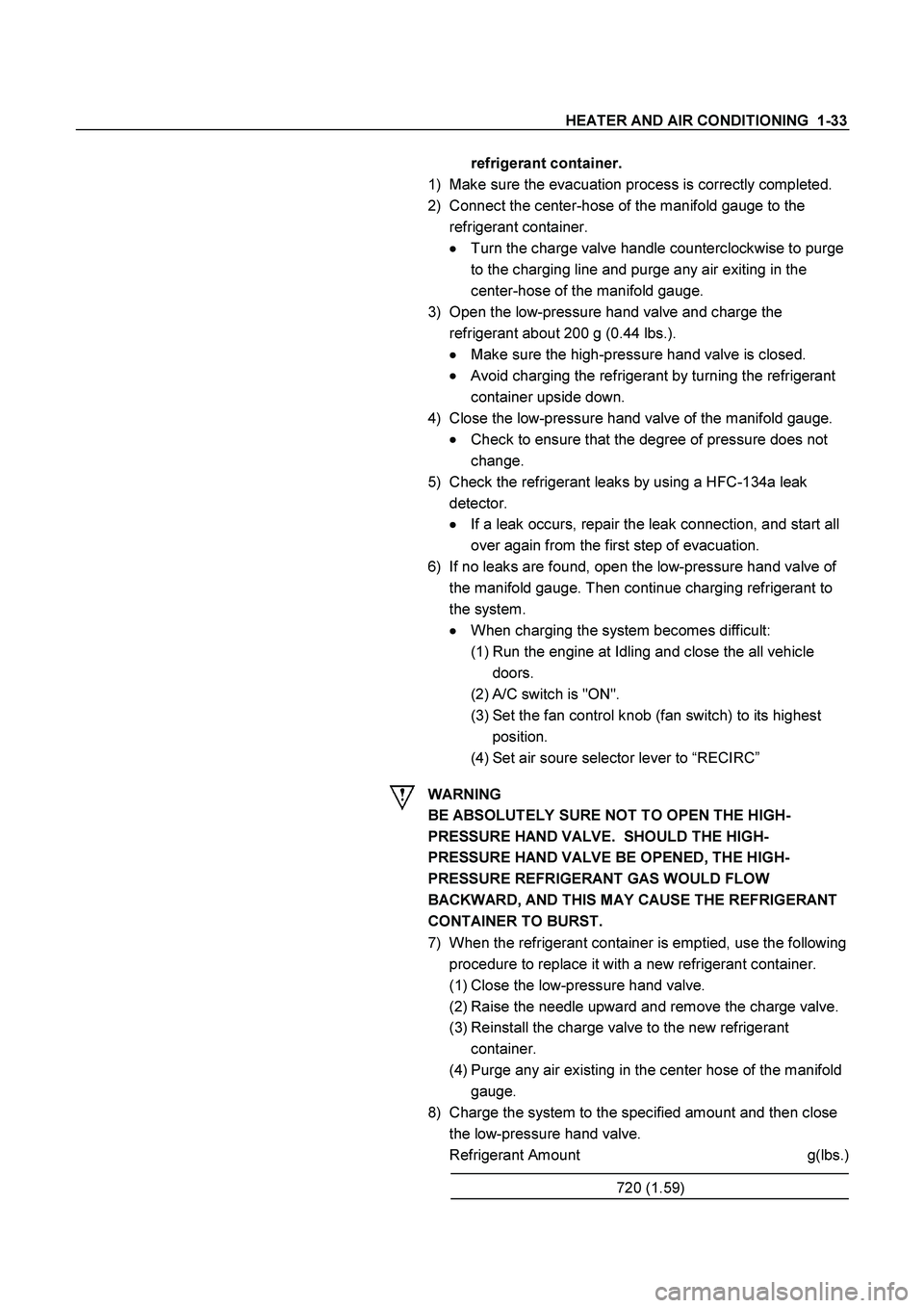
HEATER AND AIR CONDITIONING 1-33
refrigerant container.
1) Make sure the evacuation process is correctly completed.
2) Connect the center-hose of the manifold gauge to the
refrigerant container.
�
�� �
Turn the charge valve handle counterclockwise to purge
to the charging line and purge any air exiting in the
center-hose of the manifold gauge.
3) Open the low-pressure hand valve and charge the
refrigerant about 200 g (0.44 lbs.).
�
�� �
Make sure the high-pressure hand valve is closed.
�
�� �
Avoid charging the refrigerant by turning the refrigerant
container upside down.
4) Close the low-pressure hand valve of the manifold gauge.
�
�� �
Check to ensure that the degree of pressure does not
change.
5) Check the refrigerant leaks by using a HFC-134a leak
detector.
�
�� �
If a leak occurs, repair the leak connection, and start all
over again from the first step of evacuation.
6) If no leaks are found, open the low-pressure hand valve of
the manifold gauge. Then continue charging refrigerant to
the system.
�
�� �
When charging the system becomes difficult:
(1) Run the engine at Idling and close the all vehicle
doors.
(2) A/C switch is "ON".
(3) Set the fan control knob (fan switch) to its highest
position.
(4) Set air soure selector lever to “RECIRC”
WARNING
BE ABSOLUTELY SURE NOT TO OPEN THE HIGH-
PRESSURE HAND VALVE. SHOULD THE HIGH-
PRESSURE HAND VALVE BE OPENED, THE HIGH-
PRESSURE REFRIGERANT GAS WOULD FLOW
BACKWARD, AND THIS MAY CAUSE THE REFRIGERANT
CONTAINER TO BURST.
7) When the refrigerant container is emptied, use the following
procedure to replace it with a new refrigerant container.
(1) Close the low-pressure hand valve.
(2) Raise the needle upward and remove the charge valve.
(3) Reinstall the charge valve to the new refrigerant
container.
(4) Purge any air existing in the center hose of the manifold
gauge.
8) Charge the system to the specified amount and then close
the low-pressure hand valve.
Refrigerant Amount g(lbs.)
720 (1.59)
Page 3045 of 4264

HEATER AND AIR CONDITIONING 1-35
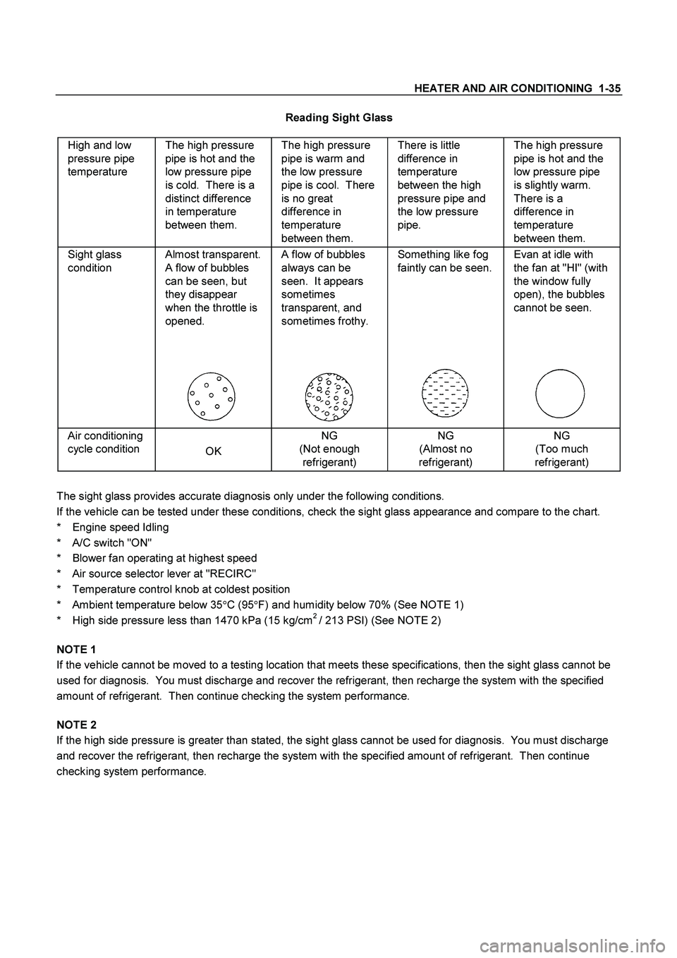
Reading Sight Glass
High and low
pressure pipe
temperature The high pressure
pipe is hot and the
low pressure pipe
is cold. There is a
distinct difference
in temperature
between them. The high pressure
pipe is warm and
the low pressure
pipe is cool. There
is no great
difference in
temperature
between them. There is little
difference in
temperature
between the high
pressure pipe and
the low pressure
pipe. The high pressure
pipe is hot and the
low pressure pipe
is slightly warm.
There is a
difference in
temperature
between them.
Sight glass
condition Almost transparent.
A flow of bubbles
can be seen, but
they disappear
when the throttle is
opened.
A flow of bubbles
always can be
seen. It appears
sometimes
transparent, and
sometimes frothy.
Something like fog
faintly can be seen.
Evan at idle with
the fan at "HI" (with
the window fully
open), the bubbles
cannot be seen.
Air conditioning
cycle condition
OK NG
(Not enough
refrigerant) NG
(Almost no
refrigerant) NG
(Too much
refrigerant)
The sight glass provides accurate diagnosis only under the following conditions.
If the vehicle can be tested under these conditions, check the sight glass appearance and compare to the chart.
* Engine speed Idling
* A/C switch "ON"
* Blower fan operating at highest speed
* Air source selector lever at "RECIRC"
* Temperature control knob at coldest position
* Ambient temperature below 35�
C (95�
F) and humidity below 70% (See NOTE 1)
* High side pressure less than 1470 kPa (15 kg/cm
2 / 213 PSI) (See NOTE 2)
NOTE 1
If the vehicle cannot be moved to a testing location that meets these specifications, then the sight glass cannot be
used for diagnosis. You must discharge and recover the refrigerant, then recharge the system with the specified
amount of refrigerant. Then continue checking the system performance.
NOTE 2
If the high side pressure is greater than stated, the sight glass cannot be used for diagnosis. You must discharge
and recover the refrigerant, then recharge the system with the specified amount of refrigerant. Then continue
checking system performance.