Page 3126 of 4264
7B-8 MSG MODEL
Exhaust Pipe
1. Remove the exhaust pipe bracket from the transmission
case.
2. Remove the exhaust pipe.
Rear Propeller Shaft (Single Shaft Type)
1. Remove the propeller shaft flange yoke at the drive pinion
side
1.
2. Remove the propeller shaft from the transmission main
shaft spline
2.
Rear Propeller Shaft (Dual Shaft Type)
1. Apply setting marks to the 2nd propeller shaft flange yoke.
This will prevent mispositioning during the installation
procedure.
2. Remove the 2nd propeller shaft flange yoke bolts at the
drive pinion side
1.
3. Remove the center bearing retainer bolts
2 .
4. Remove the 1st propeller shaft with the center bearing and
the 2nd propeller shaft.
Pull the 1st propeller shaft toward the rear of the vehicle
until the spline yoke is free of the transmission main shaft.
Harness Connector
Disconnect the back up light switch connector and the
speedometer sensor connector.
Slave Cylinder
Remove the slave cylinder from the transmission case.
Page 3131 of 4264

MSG MODEL 7B-13
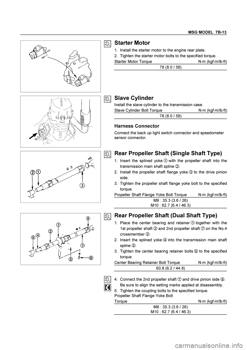
Starter Motor
1. Install the starter motor to the engine rear plate.
2. Tighten the starter motor bolts to the specified torque.
Starter Motor Torque N�
m (kgf�
m/lb�
ft)
78 (8.0 / 58)
Slave Cylinder
Install the slave cylinder to the transmission case.
Slave Cylinder Bolt Torque N�
m (kgf�
m/lb�
ft
)
78 (8.0 / 58)
Harness Connector
Connect the back up light switch connector and speedometer
sensor connector.
Rear Propeller Shaft (Single Shaft Type)
1. Insert the splined yoke 1 with the propeller shaft into the
transmission main shaft spline
2 .
2. Install the propeller shaft flange yoke
3 to the drive pinion
side.
3. Tighten the propeller shaft flange yoke bolt to the specified
torque.
Propeller Shaft Flange Yoke Bolt Torque N�m (kgf�m/lb�ft)
M8 : 35.3 (3.6 / 26)
M10 : 62.7 (6.4 / 46.3)
Rear Propeller Shaft (Dual Shaft Type)
1. Place the center bearing and retainer 1 together with the
1st propeller shaft
2 and 2nd propeller shaft 7 on the No.4
crossmember
3.
2. Insert the splined yoke
4into the transmission main shaft
spline
5.
3. Tighten the center bearing retainer bolts
6 to the specified
torque.
Center Bearing Retainer Bolt Torque N�
m (kgf�
m/lb�
ft)
60.8 (6.2 / 44.8)
4. Connect the 2nd propeller shaft
7 and drive pinion side 8.
Be sure to align the setting marks applied at disassembly.
5. Tighten the coupling bolts to the specified torque.
Propeller Shaft Flange Yoke Bolt
Torque N�
m (kgf�
m/lb�
ft)
M8 : 35.3 (3.6 / 26)
M10 : 62.7 (6.4 / 46.3)
Page 3173 of 4264
MANUAL TRANSMISSION 7B1-9
6. Remove gear control lever (5).
7. Raise and support vehicle with suitable stands.
8. Remove rear propeller shaft (6).
NOTE: Apply alignment marks on the flange at the
differential side.
401RS023
9. Loosen the front exhaust pipe fixing nuts (7) at the
engine side but not remove them. (Diesel engine
only)
150R300003
10. Remove the exhaust pipe (8). (6VE1 only)
RTW37ASH0001
11. Disconnect harness connectors and clips on the
transmission.
� Neutral Switch
�
Back up Switch
� Car Speed Sensor
12. Remove the fuel pipe bracket (9) with pipes from the
transmission (17).
Diesel engine
220R300012
Legend
(1) Bolt
(2) Nut
(3) Fuel Pipe Assembly
Page 3180 of 4264

7B1-16 MANUAL TRANSMISSION
6. Install starter(15). (Diesel engine only)
NOTE: Tighten the lower bolt temporarily.
After installing the fuel pipe assembly, tighten the bolt to
the specified torque.
Torque: 76 N�
�� �m (7.7 kg�
�� �m/56 lb�
�� �ft)
7. Install the rear support rubber (14) on the
transmission and tighten the nuts to the specified
torque.
Torque: 52 N�
�� �m (5.3 kg�
�� �m/38 lb�
�� �ft)
8. Install the middle part of transmission crossmember
(12) and bolts.
Tighten the nuts to the specified torque.
Torque: 67 N�
�� �m (6.8 kg�
�� �m/49 lb�
�� �ft)
9. Install engine rear mount nuts (11) fixing on
transmission crossmember (12).
Torque: 52 N�
�� �m (5.3 kg�
�� �m/38 lb�
�� �ft)
Remove the transmission jack from transmission
side.
10. Apply grease to top hole portion of the shift fork.
Install slave cylinder (10) and tighten the bolts to the
specified torque.
Torque: 76 N�
�� �m (7.7 kg�
�� �m/56 lb�
�� �ft)
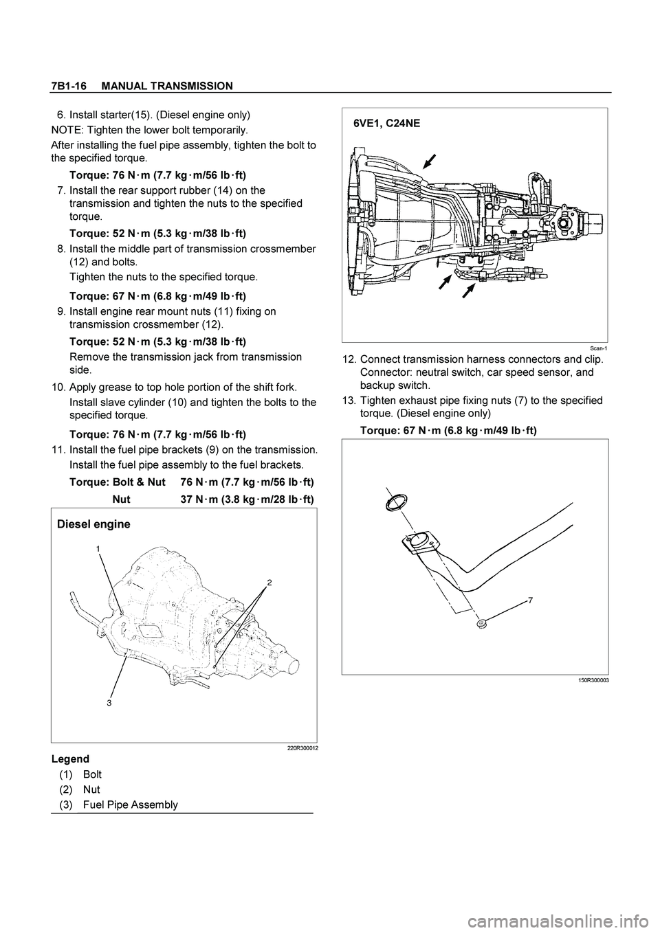
11. Install the fuel pipe brackets (9) on the transmission.
Install the fuel pipe assembly to the fuel brackets.
Torque: Bolt & Nut 76 N�
�� �m (7.7 kg�
�� �m/56 lb�
�� �ft)
Nut 37 N�
�� �
m (3.8 kg�
�� �
m/28 lb�
�� �
ft)
Diesel engine
220R300012
Legend
(1) Bolt
(2) Nut
(3) Fuel Pipe Assembly
6VE1, C24NE
Scan-1
12. Connect transmission harness connectors and clip.
Connector: neutral switch, car speed sensor, and
backup switch.
13. Tighten exhaust pipe fixing nuts (7) to the specified
torque. (Diesel engine only)
Torque: 67 N�
�� �m (6.8 kg�
�� �m/49 lb�
�� �ft)
150R300003
Page 3230 of 4264
7B1-66 MANUAL TRANSMISSION
6. Remove gear control lever (5).
7. Raise and support vehicle with suitable stands.
8. Remove rear propeller shaft (6).
NOTE: Apply alignment marks on the flange at the
differential side.
9. Remove front propeller shaft (7).
NOTE: Apply alignment marks on the flange at both
front and rear sides.
401RS023
10. Loosen the front exhaust pipe fixing nuts (8) at the
engine side but not remove them. (Diesel engine
only)
150R300004
11. Remove the exhaust pipe (9). (6VE1 only)
RTW37ASH000101
12. Disconnect harness connectors and clips on the
transfer.
�
Actuator connector
�
Car Speed Sensor
810R300069
Legend
(1) Neutral Switch Connector: Transmission
(2) Back up Switch Connector
(3) Speed Sensor Connector
(4) Actuator Connector
(5) 2W - 4W Switch Connector
(6) Neutral Switch Connector: Transfer
Page 3231 of 4264
MANUAL TRANSMISSION 7B1-67
13. Remove transmission-transfer fixing bolts (10), and
remove the transfer assembly (11) from the
transmission.
14. Disconnect harness connectors and clips on the
transmission.
�
Neutral switch; Transmission
� Back up Switch
� 2W-4W Switch
�
Neutral Switch; Transfer
15. Remove the fuel pipe brackets (12) with pipes from
the transmission (18).
Diesel engine
220R300012
Legend
(1) Bolt
(2) Nut
(3) Fuel Pipe Assembly
6VE1, C24NE
Scan-2
16. Remove slave cylinder (13) and put aside it.
220LV019
17. Support transmission with a transmission jack.
220RS0001
18. Remove engine rear mount nuts (14) from
transmission crossmember (15).
Page 3237 of 4264

MANUAL TRANSMISSION 7B1-73
6. Install starter(16).(Diesel engine)
NOTE: Tighten the lower bolt temporarily.
After installing the fuel pipe assembly, tighten the bolt to
the specified torque.
Torque: 76 N�
�� �m (7.7 kg�
�� �m/56 lb�
�� �ft)
7. Install the rear support rubber on the transmission
and tighten the bolts to the specified torque.
Torque: 50 N�
�� �m (5.1 kg�
�� �m/37 lb�
�� �ft)
8. Install the middle part of transmission crossmember
(15) and bolts.
Tighten the nuts to the specified torque.
Torque: 67 N�
�� �m (6.8 kg�
�� �m/49 lb�
�� �ft)
9. Install engine rear mount nuts (14).
Torque: 52 N�
�� �m (5.3 kg�
�� �m/38 lb�
�� �ft)
Remove the transmission jack from transmission
side.
10. Apply grease to top hole portion of the shift fork.
Install slave cylinder (13) and tighten the bolts to the
specified torque.
Torque: 76 N�
�� �m (7.7 kg�
�� �m/56 lb�
�� �ft)
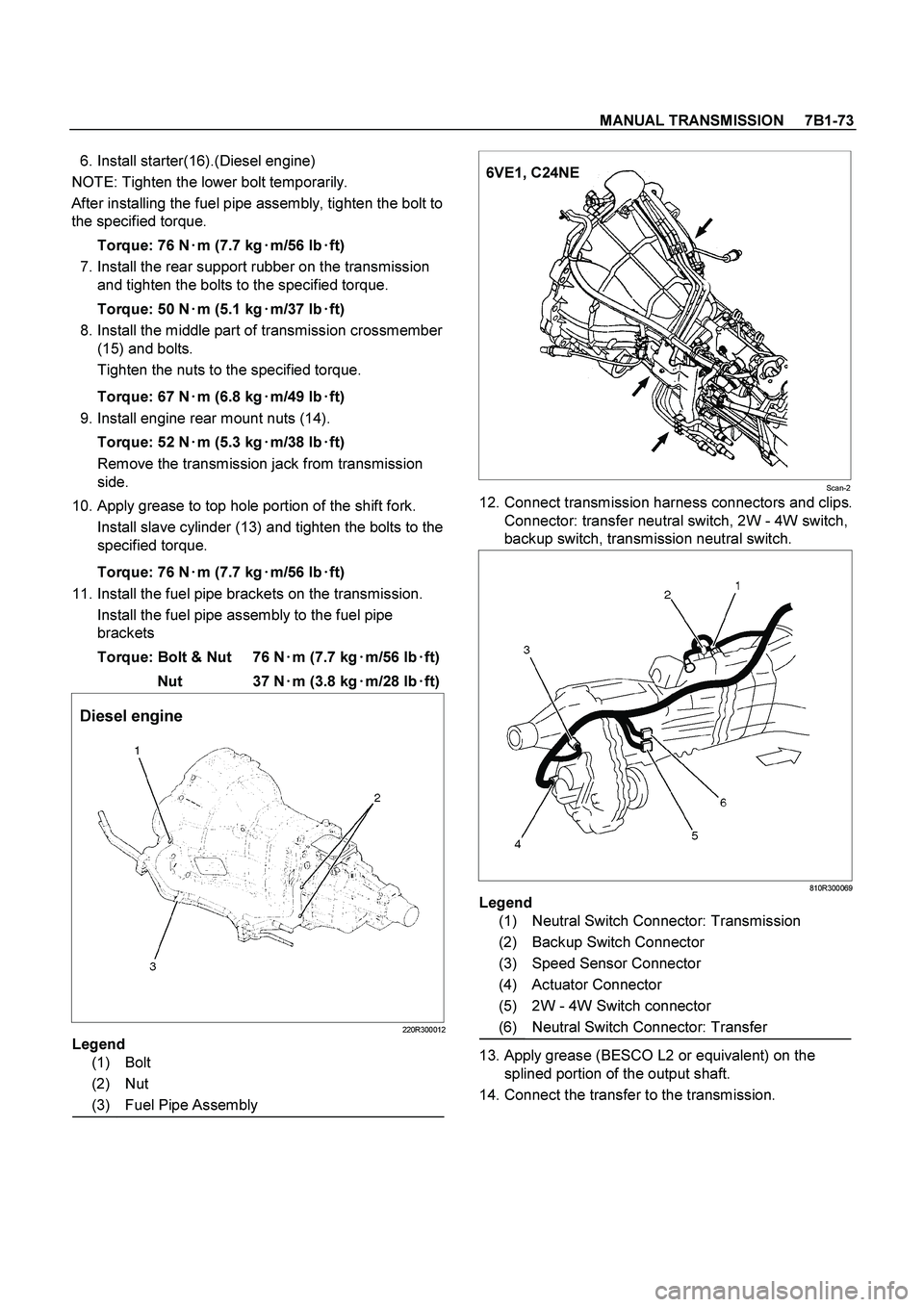
11. Install the fuel pipe brackets on the transmission.
Install the fuel pipe assembly to the fuel pipe
brackets
Torque: Bolt & Nut 76 N�
�� �m (7.7 kg�
�� �m/56 lb�
�� �ft)
Nut 37 N�
�� �m (3.8 kg�
�� �m/28 lb�
�� �ft)
Diesel engine
220R300012
Legend
(1) Bolt
(2) Nut
(3) Fuel Pipe Assembly
6VE1, C24NE
Scan-2
12. Connect transmission harness connectors and clips.
Connector: transfer neutral switch, 2W - 4W switch,
backup switch, transmission neutral switch.
810R300069
Legend
(1) Neutral Switch Connector: Transmission
(2) Backup Switch Connector
(3) Speed Sensor Connector
(4) Actuator Connector
(5) 2W - 4W Switch connector
(6) Neutral Switch Connector: Transfer
13. Apply grease (BESCO L2 or equivalent) on the
splined portion of the output shaft.
14. Connect the transfer to the transmission.
Page 3289 of 4264
IMMOBILIZER SYSTEM 11A-3
General Description
The immobilizer system consists of the four major
components which are Engine Control Module (ECM),
Immobilizer Control Unit (lCU), transponder, and scan
tool (Tech-2).
This system can be activated by a correctly programmed
transponder and starter switch is set to OFF.
This system can be deactivated by a correctl
y
programmed transponder key connected with a correctly
programmed ECM and a correctly programmed lCU.
While the system is on :
The starter cut off relay deactivates function of starter,
and the fuel injector power source is deactivated also.
�
Check Engine lamp is flashing.
�
Warning buzzer is operating.
(With antitheft system)
�
�� � Gasoline Engine (6VE1, C24SE)
LTW3BALF000101