Page 3090 of 4264
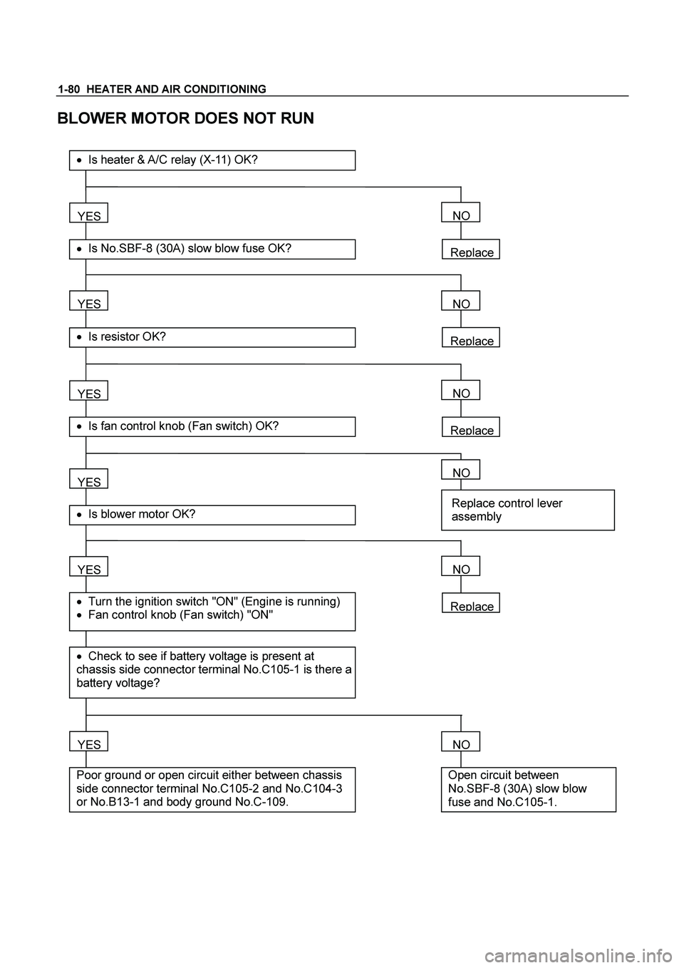
1-80 HEATER AND AIR CONDITIONING
BLOWER MOTOR DOES NOT RUN
Replace
YES
� Is No.SBF-8 (30A) slow blow fuse OK?
��Is heater & A/C relay (X-11) OK?
YES
� Is resistor OK?
YES
� Is fan control knob (Fan switch) OK?
YES
YES
� Check to see if battery voltage is present at
chassis side connector terminal No.C105-1 is there a
battery voltage?
� Turn the ignition switch "ON" (Engine is running)
� Fan control knob (Fan switch) "ON"
� Is blower motor OK?
YES
Poor ground or open circuit either between chassis
side connector terminal No.C105-2 and No.C104-3
or No.B13-1 and body ground No.C-109.
NO
Replace
NO
Replace
NO
NO
Replace control lever
assembly
Replace
NO
NO
Open circuit between
No.SBF-8 (30A) slow blow
fuse and No.C105-1.
Page 3091 of 4264
HEATER AND AIR CONDITIONING 1-81
BLOWER MOTOR DOES NOT RUN IN CERTAIN POSITION
A 1: (Low)
Blower motor does no
tB 2: (Medium Low) Position
run at
C 3: (Medium Hi)
D 4: (High)
* Checkin
g is performed only when in the malfunction
mode.
�
Is resist or OK?
YES
�
Is fan control knob (Fan switch) OK?
YES
Condition:
�
O
pen circuit between chassis side connector
terminal No. C104-2 and No. B13-3
B Condition :
�
O
pen circuit between chassis side connector
terminal No. C104-4 and No. B13-6
C Condition:
�
O
pen circuit between chassis side connector
terminal No. C104-1 and No. B13-5
D Condition:
�
O
pen circuit between chassis side connector
terminal No. C105-2 a nd No. B13-4
Replace
NO
NO
Replace control leverassembly A
Page 3092 of 4264
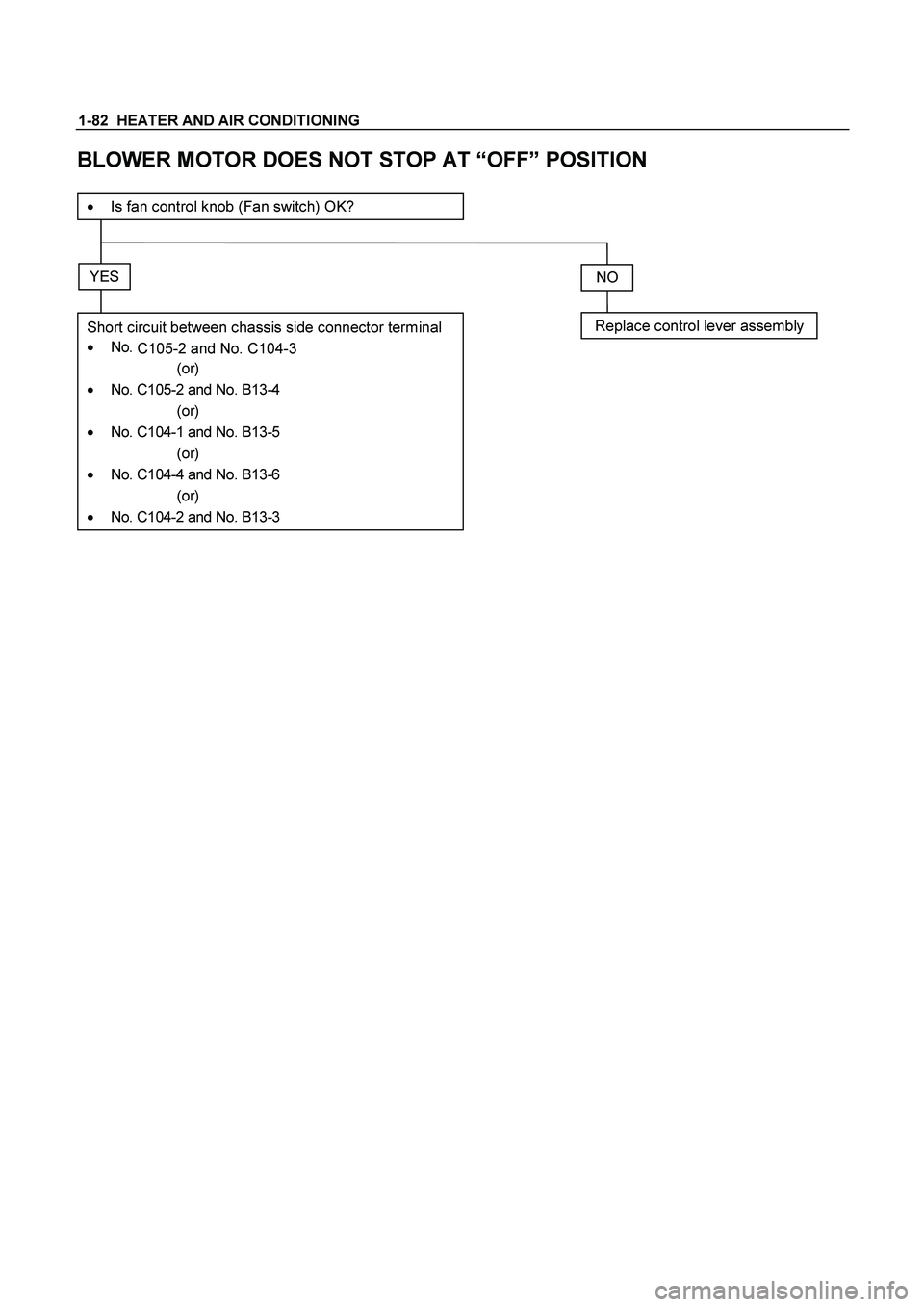
1-82 HEATER AND AIR CONDITIONING
BLOWER MOTOR DOES NOT STOP AT “OFF” POSITION
� Is fan control knob (Fan switch) OK?
YES
Short circuit between chassis side connector terminal
� No.
C105-2 and No. C104-3
(or)
�
No. C105-2 and No. B13-4
(or)
�
No. C104-1 and No. B13-5
(or)
�
No. C104-4 and No. B13-6
(or)
� No. C104-2 and No. B13-3
NO
Replace control lever assembly
Page 3093 of 4264

HEATER AND AIR CONDITIONING 1-83
AIR CONDITIONING CYCLE TROUBLESHOOTING
TROUBLE POSSIBLE CAUSE CORRECTION
No cooling or
insufficient
cooling
1. Magnetic clutch does not run
��
Refer to “MAGNETIC CLUTCH”
troubleshooting in this section
2. Compressor is not rotating properly
��Drive belt loosened or broken ��
Adjust the drive belt to the specified
tension or replace the drive belt
��Magnetic clutch face is not clean and
slips ��Clean the magnetic clutch face or replace
��
Incorrect clearance between magnetic
drive plate and pulley ��
Adjust the clearance (Refer to
“COMPRESSOR OVERHAUL”
��
Compressor oil leaks from shaft seal or
shell ��
Replace the compressor
��
Compressor seized ��
Replace the compressor
3. Insufficient or excessive charge of
refrigerant ��
Discharge and recover refrigerant.
Recharge to specified amount.
4. Leaks in the refrigerant system
��
Check refrigerant system for leaks and
repair as necessary
Discharge and recover refrigerant.
Recharge to specified amount.
5. Condenser clogged or insufficient radiation
��Clean the condenser or replace as
necessary
��
Check radiator or condenser fan function
6. Temperature control link unit of the heater
unit defective ��
Repair the link unit
7. Unsteady operation due to foreign
substance in expansion valve ��
Replace the expansion valve
8. Poor operation of electronic thermostat
��
Check electronic thermostat and replace
as necessary
Insufficient
velocity
of cooling air
1. Evaporator clogged or frosted
��
Check evaporator core and replace or
clean the core
2. Air leaking from cooling unit or air duct
��Check evaporator and duct connection,
then repair as necessary
3. Blower motor does not rotate prop-erly
��
Refer to “FAN CONTROL KNOB (FAN
SWITCH)” troubleshooting in this section
* For the execution of the charging and discharging operation in the table above, refer to the “RECOVERY,
RECYCLING, EVACUATING AND CHARGING” in this section.
Page 3094 of 4264
1-84 HEATER AND AIR CONDITIONING
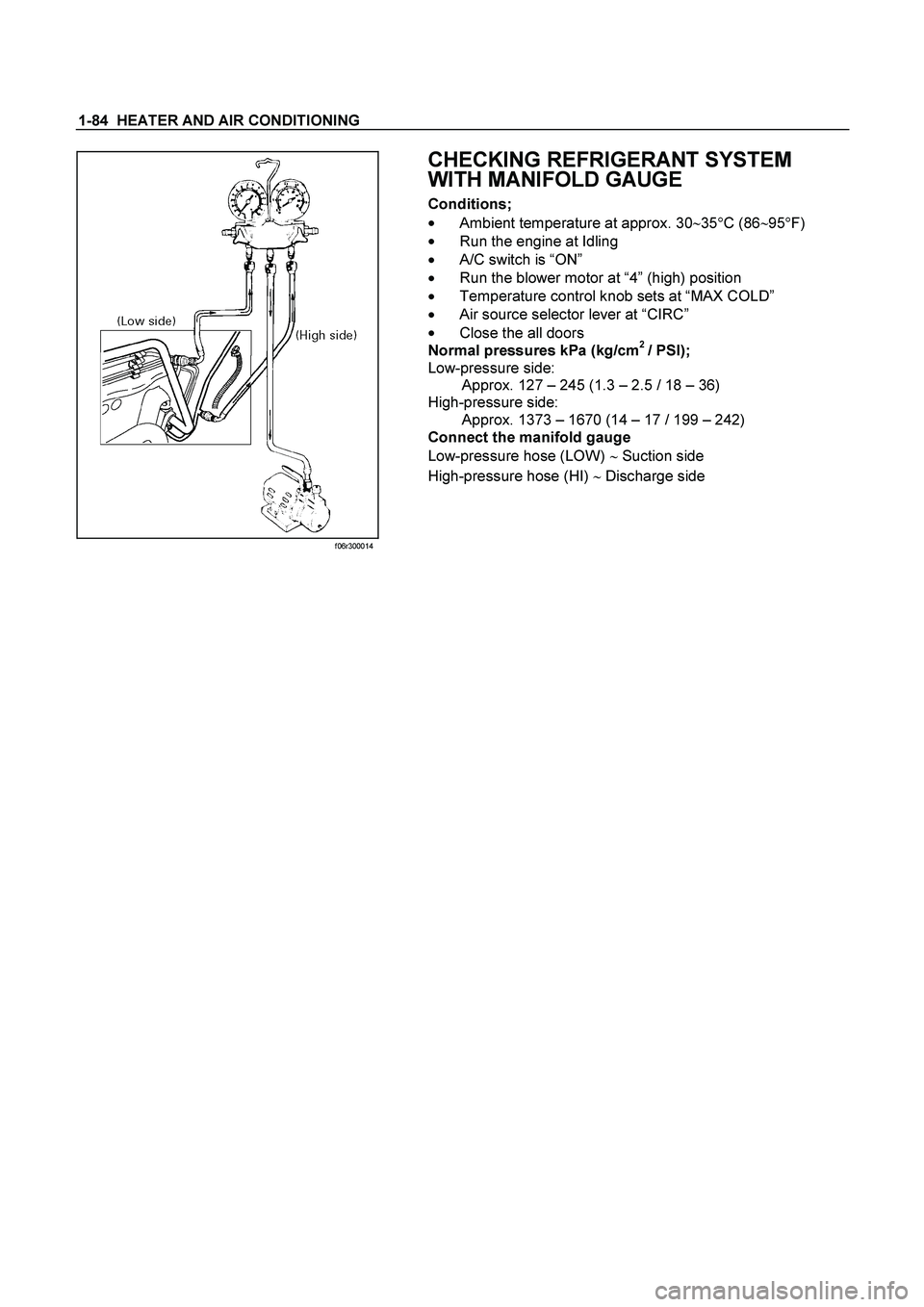
f06r300014
CHECKING REFRIGERANT SYSTEM
WITH MANIFOLD GAUGE
Conditions;
��
Ambient temperature at approx. 30�
35�
C (86�
95�
F)
��
Run the engine at Idling
��A/C switch is “ON”
��
Run the blower motor at “4” (high) position
��
Temperature control knob sets at “MAX COLD”
��
Air source selector lever at “CIRC”
��
Close the all doors
Normal pressures kPa (kg/cm
2 / PSI);
Low-pressure side:
Approx. 127 – 245 (1.3 – 2.5 / 18 – 36)
High-pressure side:
Approx. 1373 – 1670 (14 – 17 / 199 – 242)
Connect the manifold gauge
Low-pressure hose (LOW) � Suction side
High-pressure hose (HI) � Discharge side
Page 3097 of 4264
HEATER AND AIR CONDITIONING 1-87
MAGNETIC CLUTCH
When the A/C switch and the fan control knob (fan switch) are turned on with the engine running, current flows
through the thermostat and the compressor relay to activate the magnetic clutch.
The air conditioning can be stopped by turning off the A/C switch or the fan control knob (fan switch).
However, even when the air conditioning is in operation, the electronic thermostat, the pressure switch or the ECM
is used to stop the air conditioning temporarily by turning off the magnetic clutch in the prearranged conditions to
reduce the engine load which is being caused by the rise in the engine coolant temperature, and the acceleration of
the vehicle, etc.
Page 3100 of 4264
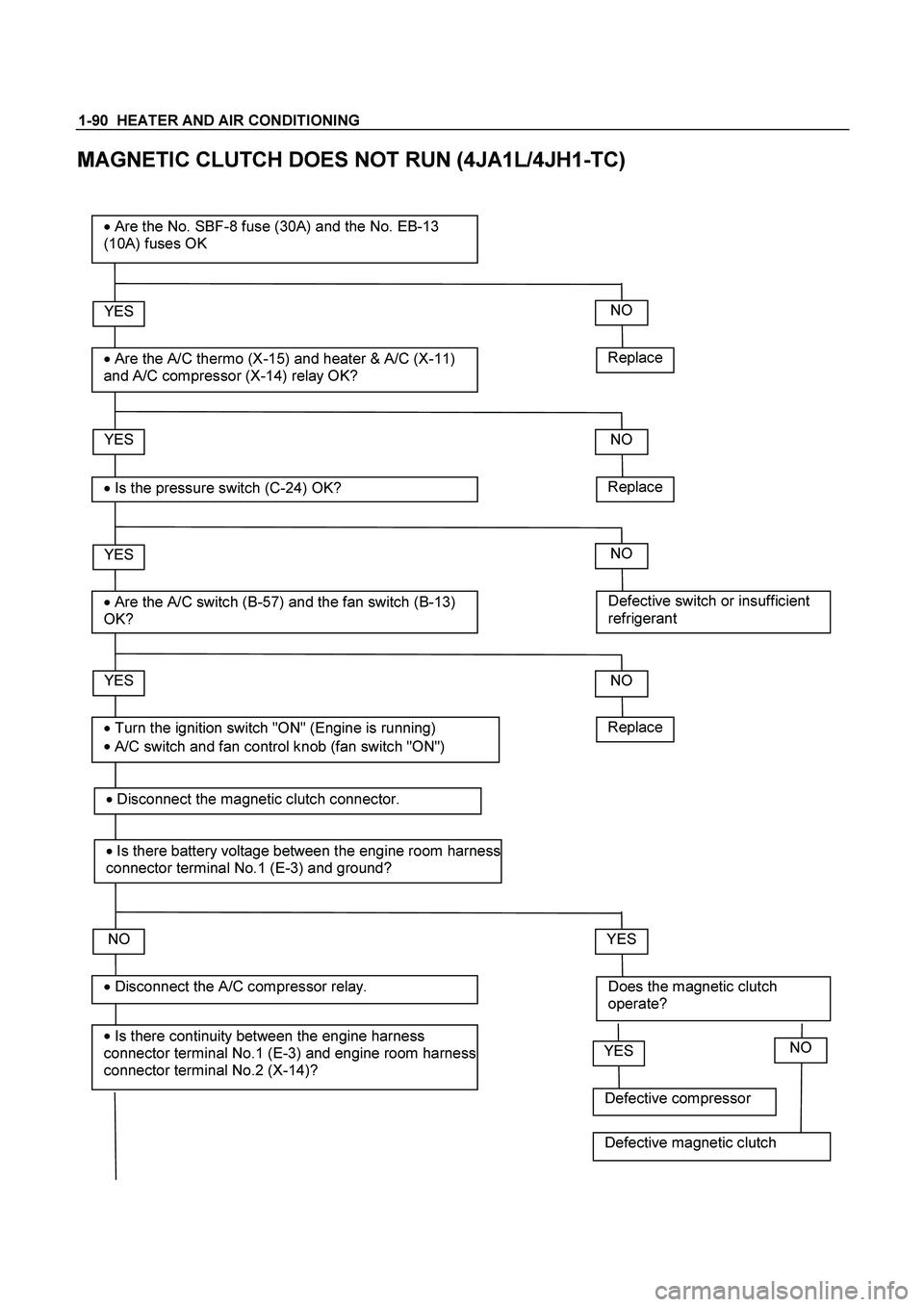
1-90 HEATER AND AIR CONDITIONING
MAGNETIC CLUTCH DOES NOT RUN (4JA1L/4JH1-TC)
Replace
YES
�
Are the A/C thermo (X-15) and heater & A/C (X-11)
and A/C compressor (X-14) relay OK?
� Are the No. SBF-8 fuse (30A) and the No. EB-13
(10A) fuses OK
YES
�
Is the pressure switch (C-24) OK?
YES
�
Are the A/C switch (B-57) and the fan switch (B-13)
OK?
NO
YES
�
Is there continuity between the engine harness
connector terminal No.1 (E-3) and engine room harness
connector terminal No.2 (X-14)?
� Disconnect the A/C compressor relay.
� Turn the ignition switch "ON" (Engine is running)
�
A/C switch and fan control knob (fan switch "ON")
NO
Replace
NO
Defective switch or insufficient
refrigerant
NO
NO
Does the magnetic clutch
operate?
YES
Replace
�
Disconnect the magnetic clutch connector.
� Is there battery voltage between the engine room harness
connector terminal No.1 (E-3) and ground?
Defective compressor
YESNO
Defective magnetic clutch
Page 3101 of 4264

and engine room harness connector
terminal No.2 (X-14).
YES
�
Is there battery v")
HEATER AND AIR CONDITIONING 1-91
Open circuit between the engine
harness connector terminal No.1 (E-3)
and engine room harness connector
terminal No.2 (X-14).
YES
�
Is there battery voltage between the engine room
harness connector terminal No.1 (X-14) and
ground?
YES
�
Disconnect the A/C thermo relay.
YES
�
Is there continuity between the ECM harness
connector terminal No.38 (C-56) and engine
room harness connector terminal No.4 (X-14)?
NO
Open circuit between the No. EB-13
fuse and engine room harness
connector terminal No.1 (X-14).
NO
Open circuit between the engine room
harness connector terminal No.1 (X-
15) and engine room harness
connector terminal No. 3 (X-14).
NO
� Is there continuity between the engine room
harness connector terminal No.3 (X-14) and No.1
(X-15)?
YES
�
Is there continuity between the ECM harness
connector terminal No.30 (C-56) and engine
room harness connector terminal No.2 (X-15)? Open circuit between the engine room
harness connector terminal No.1 (X-
15) and engine room harness
connector terminal No. 3 (X-14).
NO
YES
�
Is there battery voltage between the engine room
harness connector terminal No.4 (X-15) and
ground?
Open circuit between the ECM
harness connector No. 38 (C-56) and
engine room harness connector
terminal No. 4 (X-14).
NO
YES
�
Is there continuity between the engine room
harness connector terminal No. 3 (X-15) and the
engine room harness connector terminal No. 1 (C-
24).
Open circuit between the No. EB-13
fuse and engine room harness
connector terminal No. 4 (X-15).
NO
�
Disconnect the ECM harness connector.
�
Disconnect the pressure switch?

Blower motor does no
tB 2: (Medium Low) Position
run at
C 3: (Medium Hi)
D 4: (High)
* Checkin")
 are turned on with the engine running, current flows
through the thermostat and the comp")