2004 ISUZU TF SERIES switch
[x] Cancel search: switchPage 2641 of 4264
ENGINE DRIVEABILITY AND EMISSIONS 6E–65
Step 3: Simulate the symptom and isolate the
problem
Simulate the symptom and isolate the system by
reproducing all possible conditions suggested in Step 1
while monitoring suspected circuits/components/
systems to isolate the problem symptom. Begin with the
most logical circuit/component.
Isolate the circuit by dividing the suspect system into
simpler circuits. Nex t, confine the problem into a smaller
area of the system. Begin at the most logical point (or
point of easiest access) and thoroughly check the
isolated circuit for the fault, using basic circuit tests.
Hints
You can isolate a circuit by:
Unplugging connectors or removing a fuse to
separate one part of the circuit from another
If only component fails to operate, begin testing the
component
If a number of components do not operate, begin test
at areas of commonality (such as power sources,
ground circuits, switches, main connectors or major
components)
Substitute a known good part from the parts
department or the vehicle system
Try the suspect part in a known good vehicle
See Symptom Simulation Tests on the nex t page for
problem simulation procedures. Refer to service manual
sections 6E and 8A for information about intermittent
diagnosis. Follow procedures for basic circuit testing in
service manual section 8A.
What resources you should use
Whenever appropriate, you should use the following
resources to assist in the diagnostic process:
Service manual
Bulletins
Digital multimeter (with a MIN/MAX feature)
Tech II and Tech II upload function
Circuit testing tools (including connector kits/
harnesses and jumper wires)
Ex perience
Intermittent problem solving simulation methods
Customer complaint check sheet
Symptom Simulation Tests
1. Vibration
This method is useful when the customer complaint
analysis indicates that the problem occurs when the
vehicle/system undergoes some form of vibration.
For connectors and wire harness, slightly shake
vertically and horizontally. Inspect the connector joint
and body for damage. Also, tapping lightly along a
suspected circuit may be helpful.For parts and sensors, apply slight vibration to the part
with a light tap of the finger while monitoring the system
for a malfunction.
2. Heat
This method is important when the complaint suggests
that the problem occurs in a heated environment. Apply
moderate heat to the component with a hair drier or
similar tool while monitoring the system for a
malfunction.
CA UTION: Care must be take to avoid overheating
the component.
3. Water and Moisture
This method may be used when the complaint suggests
that the malfunction occurs on a rainy day or under
conditions of high humidity. In this case, apply water in a
light spray on the vehicle to duplicate the problem.
CA UTION: Care must be take to avoid directly
exposing electrical connections to water.
4. Electrical loads
This method involves turning systems ON (such as the
blower, lights or rear window defogger) to create a load
on the vehicle electrical system at the same time you
are monitoring the suspect circuit/component.
5e. Vehicle Operates as Designed
This condition refers to instances where a system
operating as designed is perceived to be unsatisfactory
or undesirable. In general, this is due to:
A lack of understanding by the customer
A conflict between customer ex pectations and
vehicle design intent
A system performance that is unacceptable to the
customer
What you should do
You can verify that a system is operating as designed
by:
Reviewing service manual functional/diagnostic
checks
Ex amining bulletins and other service information for
supplementary information
Compare system operation to an identical vehicle
If the condition is due to a customer misunderstanding
or a conflict between customer ex pectation and system
operation, you should ex plain the system operation to
the customer.
If the complaint is due to a case of unsatisfactory
system performance, you should contact Technical
Assistance for the latest information.
What resources you should use
Whenever possible, you should use the following
resources to facilitate the diagnostic process:
Page 2643 of 4264
ENGINE DRIVEABILITY AND EMISSIONS 6E–67
GENERAL SERVICE INFORMATION
Aftermarket Electrical and Vacuum
Equipment
Aftermarket (add-on) electrical and vacuum equipment
is defined as any equipment which connects to the
vehicle's electrical or vacuum systems that is installed
on a vehicle after it leaves the factory. No allowances
have been made in the vehicle design for this type of
equipment.
NOTE: No add-on vacuum equipment should be added
to this vehicle.
NOTE: Add-on electrical equipment must only be
connected to the vehicle's electrical system at the
battery (power and ground).
Add-on electrical equipment, even when installed to
these guidelines, may still cause the electric system to
malfunction. This may also include equipment not
connected to the vehicle electrical system such as
portable telephones and radios. Therefore, the first step
in diagnosing any electric problem is to eliminate all
aftermarket electrical equipment from the vehicle. After
this is done, if the problem still ex ists, it may be
diagnosed in the normal manner.
Electrostatic Discharge Damage
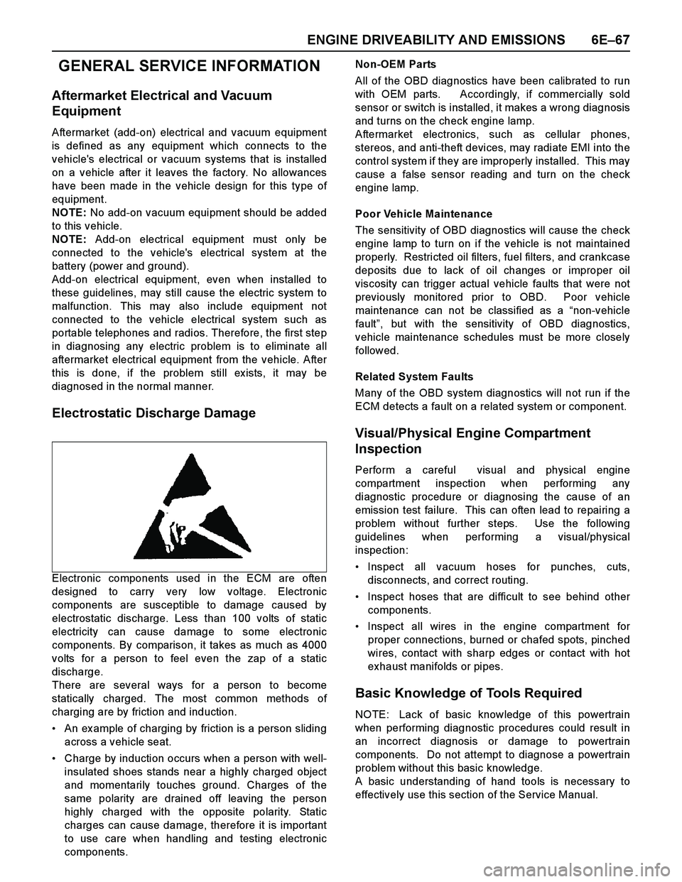
Electronic components used in the ECM are often
designed to carry very low voltage. Electronic
components are susceptible to damage caused by
electrostatic discharge. Less than 100 volts of static
electricity can cause damage to some electronic
components. By comparison, it takes as much as 4000
volts for a person to feel even the zap of a static
discharge.
There are several ways for a person to become
statically charged. The most common methods of
charging are by friction and induction.
An ex ample of charging by friction is a person sliding
across a vehicle seat.
Charge by induction occurs when a person with well-
insulated shoes stands near a highly charged object
and momentarily touches ground. Charges of the
same polarity are drained off leaving the person
highly charged with the opposite polarity. Static
charges can cause damage, therefore it is important
to use care when handling and testing electronic
components.Non-OEM Parts
All of the OBD diagnostics have been calibrated to run
with OEM parts. Accordingly, if commercially sold
sensor or switch is installed, it makes a wrong diagnosis
and turns on the check engine lamp.
Aftermarket electronics, such as cellular phones,
stereos, and anti-theft devices, may radiate EMI into the
control system if they are improperly installed. This may
cause a false sensor reading and turn on the check
engine lamp.
Poor Vehicle Maintenance
The sensitivity of OBD diagnostics will cause the check
engine lamp to turn on if the vehicle is not maintained
properly. Restricted oil filters, fuel filters, and crankcase
deposits due to lack of oil changes or improper oil
viscosity can trigger actual vehicle faults that were not
previously monitored prior to OBD. Poor vehicle
maintenance can not be classified as a “non-vehicle
fault”, but with the sensitivity of OBD diagnostics,
vehicle maintenance schedules must be more closely
follow ed.
Related System Faults
Many of the OBD system diagnostics will not run if the
ECM detects a fault on a related system or component.
Visual/Physical Engine Compartment
Inspection
Perform a careful visual and physical engine
compartment inspection when performing any
diagnostic procedure or diagnosing the cause of an
emission test failure. This can often lead to repairing a
problem without further steps. Use the following
guidelines when performing a visual/physical
inspection:
Inspect all vacuum hoses for punches, cuts,
disconnects, and correct routing.
Inspect hoses that are difficult to see behind other
components.
Inspect all wires in the engine compartment for
proper connections, burned or chafed spots, pinched
wires, contact with sharp edges or contact with hot
exhaust manifolds or pipes.
Basic Knowledge of Tools Required
NOTE: Lack of basic knowledge of this powertrain
when performing diagnostic procedures could result in
an incorrect diagnosis or damage to powertrain
components. Do not attempt to diagnose a powertrain
problem without this basic knowledge.
A basic understanding of hand tools is necessary to
effectively use this section of the Service Manual.
Page 2645 of 4264
ENGINE DRIVEABILITY AND EMISSIONS 6E–69
Reading Diagnostic Trouble Codes Using a
Tech 2
The procedure for reading diagnostic trouble code(s) is
to used a diagnostic Tech 2. When reading DTC(s),
follow instructions supplied by Tech 2 manufacturer.
Clearing Diagnostic Trouble Codes
To clear Diagnostic Trouble Codes (DTCs), use the
Te c h 2 “clear DTCs” or “clear information” function.
When clearing DTCs follow instructions supplied by the
Tech 2 manufacturer.
Diagnosis With Tech 2
If no codes are set:
Refer to F1: Data Display and identify the electrical
faults that are not indicated by trouble code.
Refer to “SYMPTOM DIAGNOSIS”.
If codes are set:
1. Record all trouble codes displayed by Tech 2 and
check id the codes are intermittent.
2. Clear the codes.
3. Drive the vehicle for a test to reproduce the faulty
status.
4. Check trouble codes again using the Tech 2.
5. If no codes is displayed by test driving, the fault is
intermittent. In this case, refer to “DIAGNOSIS
AIDS”.
6. If a code is present, refer to DTC Chart for
diagnosis.
7. Check trouble codes again using the Tech 2.
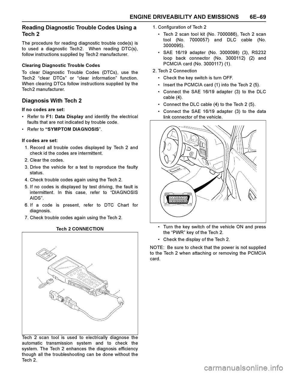
Tech 2 CONNECTION
Tech 2 scan tool is used to electrically diagnose the
automatic transmission system and to check the
system. The Tech 2 enhances the diagnosis efficiency
though all the troubleshooting can be done without the
Te c h 2 .1. Configuration of Tech 2
Tech 2 scan tool kit (No. 7000086), Tech 2 scan
tool (No. 7000057) and DLC cable (No.
3000095).
SAE 16/19 adapter (No. 3000098) (3), RS232
loop back connector (No. 3000112) (2) and
PCMCIA card (No. 3000117) (1).
2. Tech 2 Connection
Check the key switch is turn OFF.
Insert the PCMCIA card (1) into the Tech 2 (5).
Connect the SAE 16/19 adapter (3) to the DLC
cable (4).
Connect the DLC cable (4) to the Tech 2 (5).
Connect the SAE 16/19 adapter (3) to the data
link connector of the vehicle.
Turn the key switch of the vehicle ON and press
the “PWR” key of the Tech 2.
Check the display of the Tech 2.
NOTE: Be sure to check that the power is not supplied
to the Tech 2 when attaching or removing the PCMCIA
card.
Page 2649 of 4264
ENGINE DRIVEABILITY AND EMISSIONS 6E–73
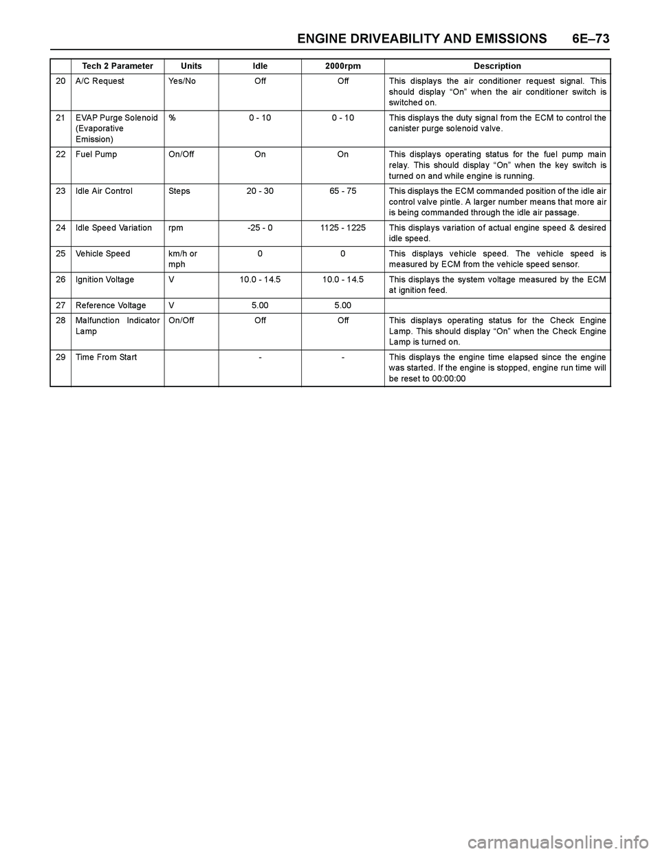
20 A/C Reque st Ye s/NoOffOff This displays the air conditioner request signal. This
should display “On” whe n the air conditio ne r switch is
switche d o n.
21 EVAP Purge So le no id
(Evaporative
Emission)%0 - 100 - 10 This display s the duty signa l fro m the ECM to co ntrol the
ca nister purge so le no id v alve .
22 Fuel Pump On/OffOnOn This displays operating status for the fuel pump main
relay. This should display “On” when the key switch is
turned on and while engine is running.
23 Idle Air Contro l Ste ps20 - 3065 - 75 This displays the ECM commanded position of the idle air
control valve pintle. A larger number means that more air
is being commanded through the idle air passage.
24 Idle Speed Variation rpm-25 - 01125 - 1225 This displays variation of actual engine speed & desired
idle speed.
25 Vehicle Speed km/h or
mph00 This displays vehicle speed. The vehicle speed is
me asured by ECM from the v ehicle spe ed senso r.
26 Ignition Voltage V10.0 - 14.510.0 - 14.5 This displays the system voltage measured by the ECM
at ignition feed.
27 Reference Voltage V5.005.00
28 Ma lfunctio n Indicato r
La mpOn/OffOffOff This displays operating status for the Check Engine
La mp. This sho uld displa y “On” when the Check Engine
Lamp is turned on.
29Time From Start--This displays the engine time elapsed since the engine
was started. If the engine is stopped, engine run time will
be rese t to 00:00:00
Tech 2 ParameterUnitsIdle2000rpmDescription
Page 2652 of 4264
6E–76 ENGINE DRIVEABILITY AND EMISSIONS
MISCELLANEOUS TEST
The state of each circuit can be tested by using
miscellaneous test menus. Especially when DTC
cannot be detected, a faulty circuit can be diagnosed by
testing each circuit by means of these menus.
Even DTC has been detected, the circuit tests using
these menus could help discriminate between a
mechanical trouble and an electrical trouble.
Connect Tech 2 and select “Powertrain”, “2.XL L4
HV240” & “Miscellaneous Test”.
F0: Lamps
F0: Malfunction Indicator Lamp
When the Tech 2 is operated, “Malfunction Indicator
Lamp (Check Engine Lamp)” is turned on or off.
The circuit is normal if the “Malfunction Indicator Lamp
(Check Engine Lamp)” in the instrument panel is turned
on or off in accordance with this operation.
F1: Relays
F0: Fuel Pump Relay
When the Tech 2 is operated, fuel pump relay signal
turns ON or OFF.
The circuit is normal if fuel pump sound is generated in
accordance with this operation when key switch is
turned ON.
F1: A /C Clutch Relay
When the Tech 2 is operated, A/C clutch relay signal
turns ON or OFF.
The circuit is normal if A/C compressor clutch is
energized in accordance with this operation when the
engine is running.
F2: EVAP
F0: Purge Solenoid
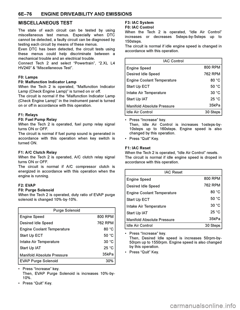
When the Tech 2 is operated, duty ratio of EVAP purge
solenoid is changed 10%-by-10%.
Press “Increase” key.
Then, EVAP Purge Solenoid is increases 10%-by-
10%.
Press “Quit” Key.F3: IAC System
F0: IA C Control
When the Tech 2 is operated, “Idle Air Control”
increases or decreases 5steps-by-5steps up to
150steps.
The circuit is normal if idle engine speed is changed in
accordance with this operation.
Press “Increase” key.
Then, Idle Air Control is increases 1osteps-by-
10steps up to 160steps. Engine speed is also
changed by this operation.
Press “Quit” Key.
F1: IA C Reset
When the Tech 2 is operated, “Idle Air Control” resets.
The circuit is normal if idle engine speed is droped in
accordance with this operation.
Press “Increase” key.
Then, Desired Idle speed is increases 50rpm-by-
50rpm up to 1550rpm. Engine speed is also changed
by this operation.
Press “Quit” Key. Purge Solenoid
Engine Speed 800 RPM
Desired Idle Speed 762 RPM
Engine Coolant Temperature 80 °C
Start Up ECT 50 °C
Intake Air Temperature 30 °C
Start Up IAT 25 °C
Manifold Absolute Pressure 35kPa
EVAP Purge Solenoid 30%
IAC Control
Engine Speed 800 RPM
Desired Idle Speed 762 RPM
Engine Coolant Temperature 80 °C
Start Up ECT 50 °C
Intake Air Temperature 30 °C
Start Up IAT25 °C
Manifold Absolute Pressure 35kPa
Idle Air Control 30 Steps
IAC Reset
Engine Speed 800 RPM
Desired Idle Speed 762 RPM
Engine Coolant Temperature 80 °C
Start Up ECT 50 °C
Intake Air Temperature 30 °C
Start Up IAT 25 °C
Manifold Absolute Pressure 35kPa
Idle Air Control 30 Steps
Page 2661 of 4264
ENGINE DRIVEABILITY AND EMISSIONS 6E–85
2. Demand of Data
1. Connect Tech-2 to the vehicle. When activated by
turning on the power of Tech-2, push the “Enter”
switch.
2. Turn on the ignition switch (without starting the
engine)
3. In the main menu of Diagnostic Tester, push “F1:
Service Programming System (SPS)”.
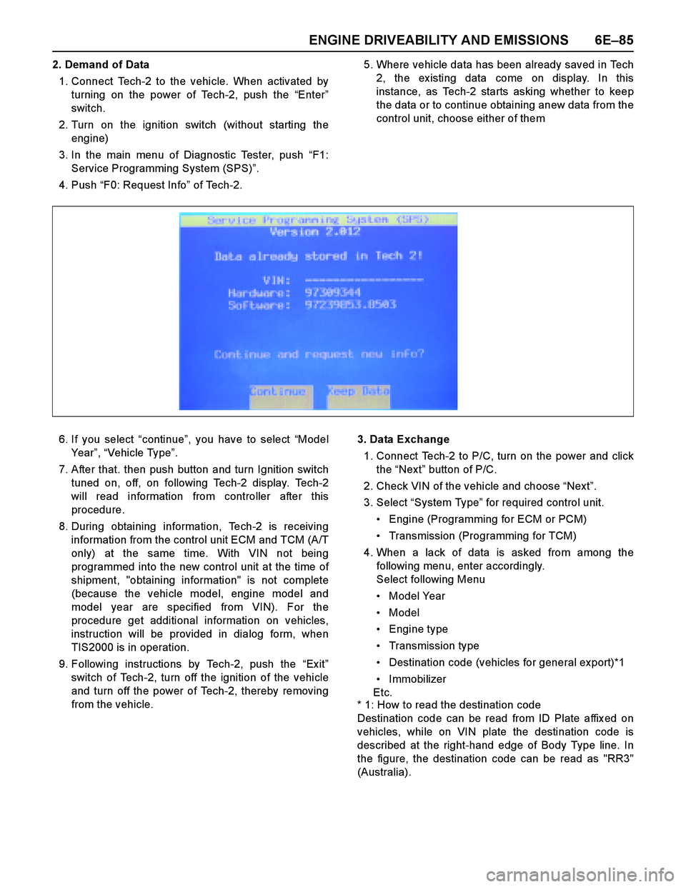
4. Push “F0: Request Info” of Tech-2.5. Where vehicle data has been already saved in Tech
2, the ex isting data come on display. In this
instance, as Tech-2 starts asking whether to keep
the data or to continue obtaining anew data from the
control unit, choose either of them
6. If you select “continue”, you have to select “Model
Year”, “Vehicle Type”.
7. After that. then push button and turn Ignition switch
tuned on, off, on following Tech-2 display. Tech-2
will read information from controller after this
procedure.
8. During obtaining information, Tech-2 is receiving
information from the control unit ECM and TCM (A/T
only) at the same time. With VIN not being
programmed into the new control unit at the time of
shipment, "obtaining information" is not complete
(because the vehicle model, engine model and
model year are specified from VIN). For the
procedure get additional information on vehicles,
instruction will be provided in dialog form, when
TIS2000 is in operation.
9. Following instructions by Tech-2, push the “Ex it”
switch of Tech-2, turn off the ignition of the vehicle
and turn off the power of Tech-2, thereby removing
from the vehicle.3. Data Exchange
1. Connect Tech-2 to P/C, turn on the power and click
the “Next” button of P/C.
2. Check VIN of the vehicle and choose “Next”.
3. Select “System Type” for required control unit.
Engine (Programming for ECM or PCM)
Transmission (Programming for TCM)
4. When a lack of data is asked from among the
following menu, enter accordingly.
Select following Menu
Model Year
Model
Engine type
Transmission type
Destination code (vehicles for general export)*1
Immobilizer
Etc.
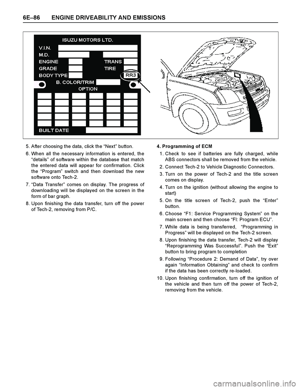
* 1: How to read the destination code
Destination code can be read from ID Plate affix ed on
vehicles, while on VIN plate the destination code is
described at the right-hand edge of Body Type line. In
the figure, the destination code can be read as "RR3"
(Australia).
Page 2662 of 4264
6E–86 ENGINE DRIVEABILITY AND EMISSIONS
5. After choosing the data, click the “Nex t” button.
6. When all the necessary information is entered, the
“details” of software within the database that match
the entered data will appear for confirmation. Click
the “Program” switch and then download the new
software onto Tech-2.
7.“Data Transfer” comes on display. The progress of
downloading will be displayed on the screen in the
form of bar graph.
8. Upon finishing the data transfer, turn off the power
of Tech-2, removing from P/C.4. Programming of ECM
1. Check to see if batteries are fully charged, while
ABS connectors shall be removed from the vehicle.
2. Connect Tech-2 to Vehicle Diagnostic Connectors.
3. Turn on the power of Tech-2 and the title screen
comes on display.
4. Turn on the ignition (without allowing the engine to
start)
5. On the title screen of Tech-2, push the “Enter”
button.
6. Choose “F1: Service Programming System” on the
main screen and then choose “Fl: Program ECU”.
7. While data is being transferred, “Programming in
Progress” will be displayed on the Tech-2 screen.
8. Upon finishing the data transfer, Tech-2 will display
“Reprogramming Was Successful”. Push the “Exit”
button to bring program to completion
9. Following “Procedure 2: Demand of Data”, try over
again “Information Obtaining” and check to confirm
if the data has been correctly re-loaded.
10. Upon finishing confirmation, turn off the ignition of
the vehicle and then turn off the power of Tech-2,
removing from the vehicle.
Page 2674 of 4264
6E–98 ENGINE DRIVEABILITY AND EMISSIONS
FUEL METERING SYSTEM CHECK
Some failures of the fuel metering system will result in
an “Engine Cranks But Will Not Run” symptom. If this
condition ex ists, refer to the Cranks But Will Not Run
chart. This chart will determine if the problem is caused
by the ignition system, the ECM, or the fuel pump
electrical circuit.
Refer to Fuel System Electrical Test for the fuel system
wiring schematic.
If there is a fuel delivery problem, refer to Fuel System
Diagnosis, which diagnoses the fuel injectors, the fuel
pressure regulator, and the fuel pump.
Followings are applicable to the vehicles with
closed Loop System:
If a malfunction occurs in the fuel metering system, it
usually results in either a rich HO2S signal or a lean
HO2S signal. This condition is indicated by the HO2S
voltage, which causes the ECM to change the fuel
calculation (fuel injector pulse width) based on the
HO2S reading. Changes made to the fuel calculation
will be indicated by a change in the long term fuel trim
values which can be monitored with a Scan Tool. Ideal
long term fuel trim values are around 0%; for a lean
HO2S signal, the ECM will add fuel, resulting in a fuel
trim value above 0%. Some variations in fuel trim values
are normal because all engines are not ex actly the
same. If the evaporative emission canister purge is 02
status may be rich condition. 02 status indicates the
lean condition, refer to DTC P1171 for items which can
cause a lean HO2S signal.
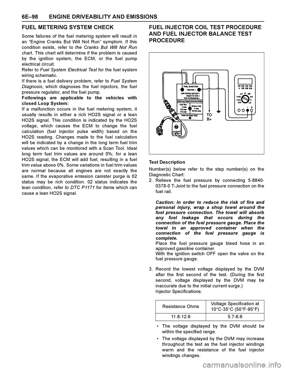
FUEL INJECTOR COIL TEST PROCEDURE
AND FUEL INJECTOR BALANCE TEST
PROCEDURE
Test Description
Number(s) below refer to the step number(s) on the
Diagnostic Chart:
2. Relieve the fuel pressure by connecting 5-8840-
0378-0 T-Joint to the fuel pressure connection on the
fuel rail.
Caution: In order to reduce the risk of fire and
personal injury, wrap a shop towel around the
fuel pressure connection. The towel will absorb
any fuel leakage that occurs during the
connection of the fuel pressure gauge. Place the
towel in an approved container when the
connection of the fuel pressure gauge is
complete.
Place the fuel pressure gauge bleed hose in an
approved gasoline container.
With the ignition switch OFF open the valve on the
fuel pressure gauge.
3. Record the lowest voltage displayed by the DVM
after the first second of the test. (During the first
second, voltage displayed by the DVM may be
inaccurate due to the initial current surge.)
Injector Specifications:
The voltage displayed by the DVM should be
within the specified range.
The voltage displayed by the DVM may increase
throughout the test as the fuel injector windings
warm and the resistance of the fuel injector
windings changes.Resistance OhmsVoltage Specification at
10°C-35°C (50°F-95°F)
11.8-12.6 5.7-6.6