2004 ISUZU TF SERIES lock
[x] Cancel search: lockPage 1459 of 4264
4JA1/4JH1 ENGINE DRIVEABILITY AND EMISSIONS 6E–87
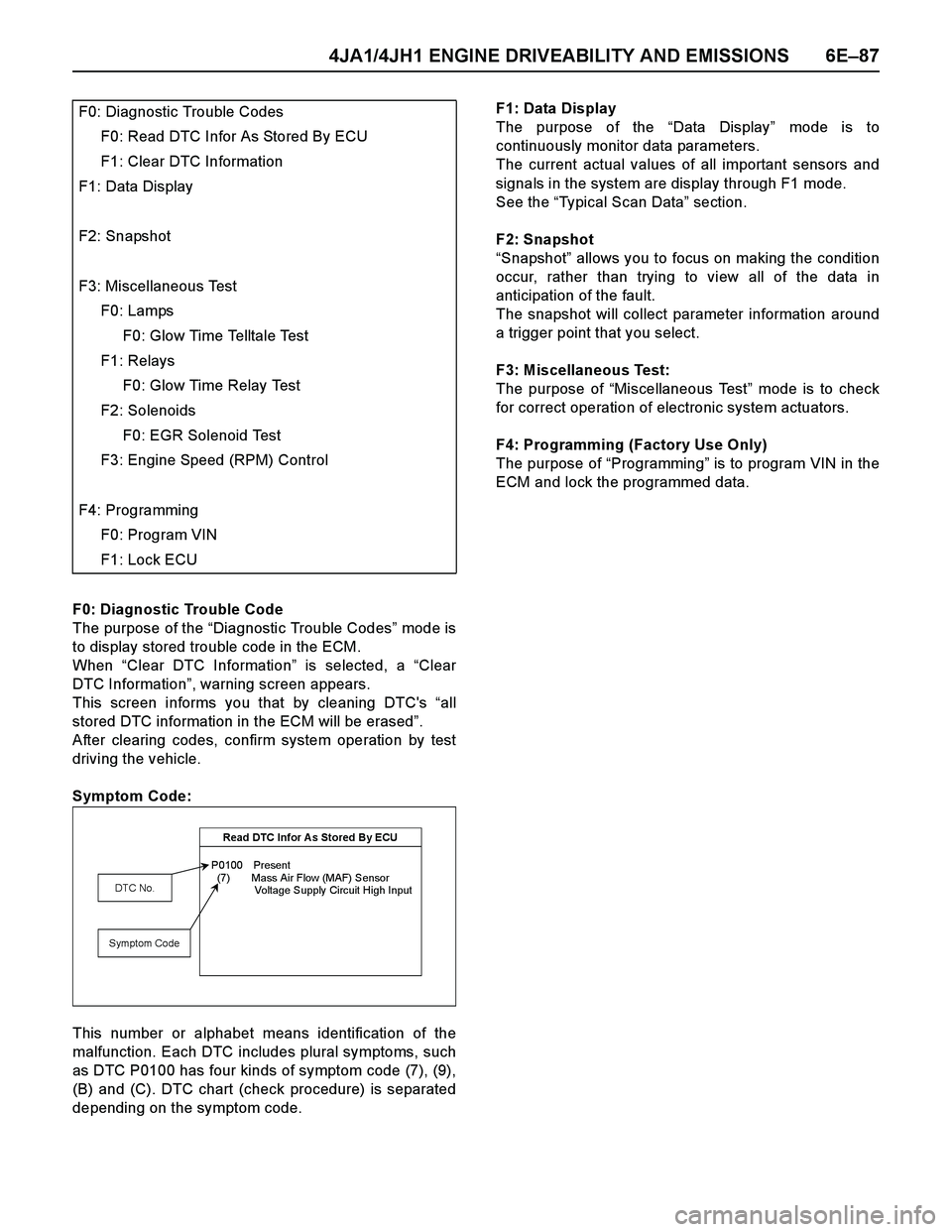
F0: Diagnostic Trouble Code
The purpose of the “Diagnostic Trouble Codes” mod e i s
to display stored trouble code in the ECM.
When “Clear DTC Information” is selected, a “Clear
DTC Information”, warning screen appears.
This screen informs you that by cleaning DTC's “all
stored DTC information in the ECM will be erased”.
After clearing codes, confirm system operation by test
driving the vehicle.
Symptom Code:
This number or alphabet means identification of the
malfunction. Each DTC includes plural symptoms, such
as DTC P0100 has four kinds of symptom code (7), (9),
(B) and (C). DTC chart (check procedure) is separated
depending on the symptom code.F1: Data Display
The purpose of the “Data Display” mode is to
continuously monitor data parameters.
The current actual values of all important sensors and
signals in the system are display through F1 mode.
See the “Typical Scan Data” section.
F2: Snapshot
“Snapshot” allows you to focus on making the condition
occur, rather than trying to view all of the data in
anticipation of the fault.
The snapshot will collect parameter information around
a trigger point that you select.
F3: Miscellaneous Test:
The purpose of “Miscellaneous Test” mode is to check
for correct operation of electronic system actuators.
F4: Programming (Factory Use Only)
The purpose of “Programming” is to program VIN in the
ECM and lock the programmed data. F0: Diagnostic Trouble Codes
F0: Read DTC Infor As Stored By ECU
F1: Clear DTC Information
F1: Data Display
F2: Snapshot
F3: Miscellaneous Test
F0: Lamps
F0: Glow Time Telltale Test
F1: Relays
F0: Glow Time Relay Test
F2: Solenoids
F0: EGR Solenoid Test
F3: Engine Speed (RPM) Control
F4: Programming
F0: Program VIN
F1: Lock ECU
Read DTC Infor A s Stored By ECU
P0100 Present
(7) Mass Air Flow (MAF) Sensor
Voltage Supply Circuit High Input
DTC No.
Symptom Code
Page 1477 of 4264
4JA1/4JH1 ENGINE DRIVEABILITY AND EMISSIONS 6E–105
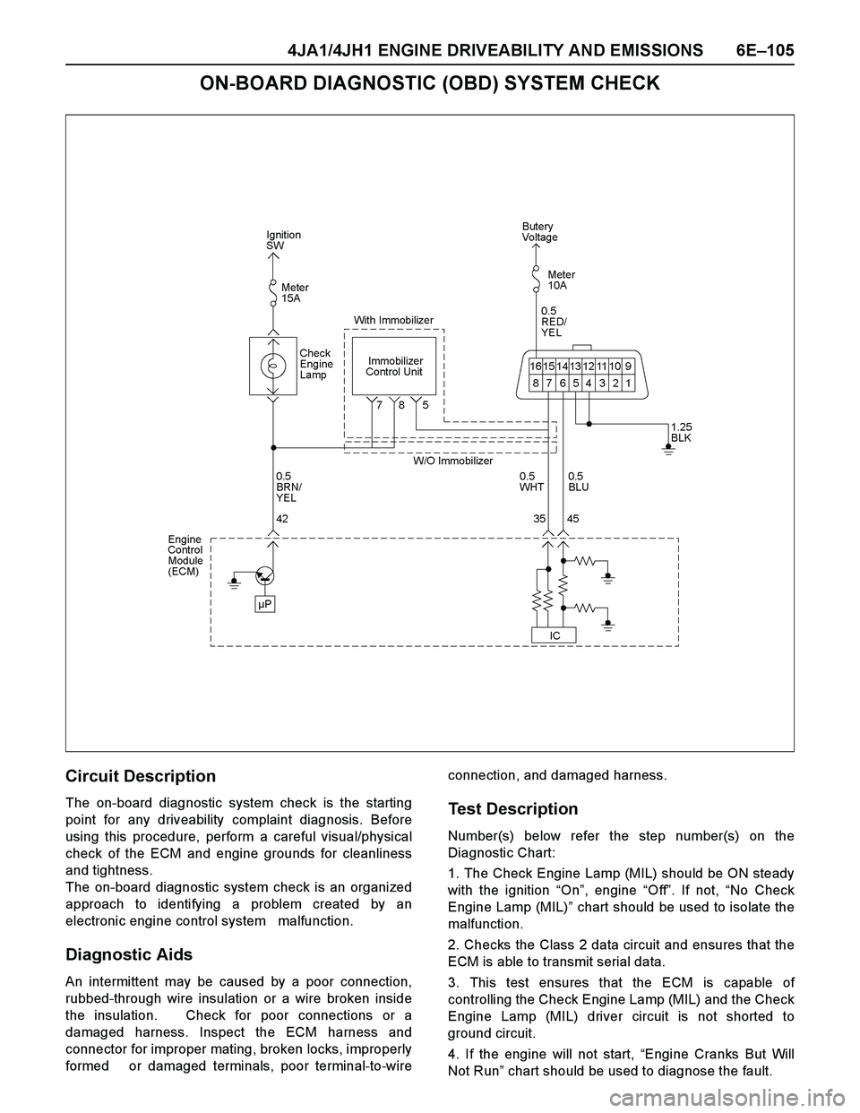
ON-BOARD DIAGNOSTIC (OBD) SYSTEM CHECK
Circuit Description
The on-board diagnostic system check is the starting
point for any driveability complaint diagnosis. Before
using this procedure, perform a careful visual/physical
check of the ECM and engine grounds for cleanliness
and tightness.
The on-board diagnostic system check is an organized
approach to identifying a problem created by an
electronic engine control system malfunction.
Diagnostic Aids
An intermittent may be caused by a poor connection,
rubbed-through wire insulation or a wire broken inside
the insulation. Check for poor connections or a
damaged harness. Inspect the ECM harness and
connector for improper mating, broken locks, improperly
formed or damaged terminals, poor terminal-to-wireconnection, and damaged harness.
Test Description
Number(s) below refer the step number(s) on the
Diagnostic Chart:
1. The Check Engine Lamp (MIL) should be ON steady
with the ignition “On”, engine “Off”. If not, “No Check
Engine Lamp (MIL)” chart should be used to isolate the
malfunction.
2. Checks the Class 2 data circuit and ensures that the
ECM is able to transmit serial data.
3. This test ensures that the ECM is capable of
controlling the Check Engine Lamp (MIL) and the Check
Engine Lamp (MIL) driver circuit is not shorted to
ground circuit.
4. If the engine will not start, “Engine Cranks But Will
Not Run” chart should be used to diagnose the fault.
Page 1481 of 4264
4JA1/4JH1 ENGINE DRIVEABILITY AND EMISSIONS 6E–109
NO CHECK ENGINE LAMP (MIL)
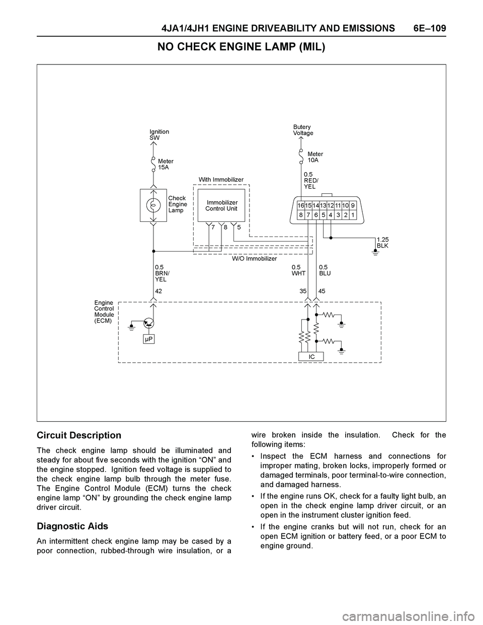
Circuit Description
The check engine lamp should be illuminated and
steady for about five seconds with the ignition “ON” and
the engine stopped. Ignition feed voltage is supplied to
the check engine lamp bulb through the meter fuse.
The Engine Control Module (ECM) turns the check
engine lamp “ON” by grounding the check engine lamp
driver circuit.
Diagnostic Aids
An intermittent check engine lamp may be cased by a
poor connection, rubbed-through wire insulation, or awire broken inside the insulation. Check for the
following items:
Inspect the ECM harness and connections for
improper mating, broken locks, improperly formed or
damaged terminals, poor terminal-to-wire connection,
and damaged harness.
If the engine runs OK, check for a faulty light bulb, an
open in the check engine lamp driver circuit, or an
open in the instrument cluster ignition feed.
If the engine cranks but will not run, check for an
open ECM ignition or battery feed, or a poor ECM to
engine ground.
Page 1484 of 4264
6E–112 4JA1/4JH1 ENGINE DRIVEABILITY AND EMISSIONS
CHECK ENGINE LAMP (MIL) “ON” STEADY
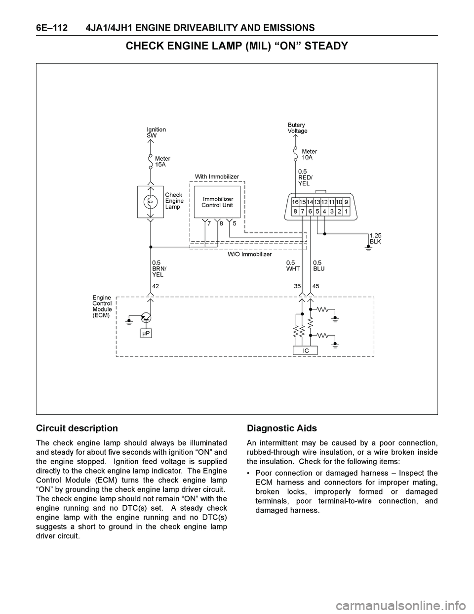
Circuit description
The check engine lamp should always be illuminated
and steady for about five seconds with ignition “ON” and
the engine stopped. Ignition feed voltage is supplied
directly to the check engine lamp indicator. The Engine
Control Module (ECM) turns the check engine lamp
“ON” by grounding the check engine lamp driver circuit.
The check engine lamp should not remain “ON” with the
engine running and no DTC(s) set. A steady check
engine lamp with the engine running and no DTC(s)
suggests a short to ground in the check engine lamp
driver circuit.
Diagnostic Aids
An intermittent may be caused by a poor connection,
rubbed-through wire insulation, or a wire broken inside
the insulation. Check for the following items:
Poor connection or damaged harness – Inspect the
ECM harness and connectors for improper mating,
broken locks, improperly formed or damaged
terminals, poor terminal-to-wire connection, and
damaged harness.
Page 1501 of 4264
4JA1/4JH1 ENGINE DRIVEABILITY AND EMISSIONS 6E–129
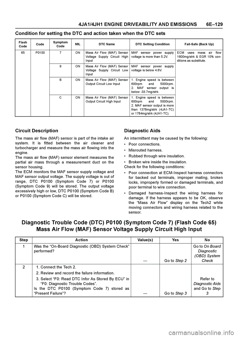
Condition for setting the DTC and action taken when the DTC sets
Circuit Description
The mass air flow (MAF) sensor is part of the intake air
system. It is fitted between the air cleaner and
turbocharger and measure the mass air flowing into the
engine.
The mass air flow (MAF) sensor element measures the
partial air mass through a measurement duct on the
sensor housing.
The ECM monitors the MAF sensor supply voltage and
MAF sensor output voltage. The supply voltage is out of
range, DTC P0100 (Symptom Code 7) or P0100
(Symptom Code 9) will be stored. The output voltage
ex cessively high or low, DTC P0100 (Symptom Code B)
or P0100 (Symptom Code C) will be stored.
Diagnostic Aids
An intermittent may be caused by the following:
Poor connections.
Misrouted harness.
Rubbed through wire insulation.
Broken wire inside the insulation.
Check for the following conditions:
Poor connection at ECM-Inspect harness connectors
for backed out terminals, improper mating, broken
locks, improperly formed or damaged terminals, and
poor terminal to wire connection.
Damaged harness-Inspect the wiring harness for
damage. If the harness appears to be OK, observe
the “Mass Air Flow” display on the Tech2 while
moving connectors and wiring harness related to the
sensor.
Diagnostic Trouble Code (DTC) P0100 (Symptom Code 7) (Flash Code 65)
Mass Air Flow (MAF) Sensor Voltage Supply Circuit High Input
Flash
CodeCodeSymptom
CodeMIL DTC Name DTC Setting Condition Fail-Safe (Back Up)
65 P0100 7 ON Ma ss Air Flo w (MAF) Senso r
Voltage Supply Circuit High
InputMAF sensor power supply
voltage is more than 5.2V.ECM uses ma ss a ir flo w
1600mg/strk & EGR 10% co n-
ditions as substitute.
9 ON Mass Air Flow (MAF) Sensor
Voltage Supply Circuit Low
InputMAF sensor power supply
voltage is below 4.6V.
B ON Mass Air Flow (MAF) Sensor
Output Circuit Low Input1. Engine speed is between
600rpm and 5000rpm.
2. MAF se nsor o utput is
below -33.7mg/strk.
C ON Mass Air Flow (MAF) Sensor
Output Circuit High Input1. Engine speed is between
600rpm and 5000rpm.
2. MAF sensor output is more
tha n 1378mg/strk (4JA1-TC)
o r 1784mg/strk (4JH1-TC).
Step Action Value(s) Yes No
1Was the “On-Board Diagnostic (OBD) System Check”
performed?
—Go to Step 2Go to On Board
Diagnostic
(OBD) System
Check
2 1. Connect the Tech 2.
2. Review and record the failure information.
3. Select “F0: Read DTC Infor As Stored By ECU” in
“F0: Diagnostic Trouble Codes”.
Is the DTC P0100 (Symptom Code 7) stored as
“Present Failure”?—Go to Step 3Refer to
Diagnostic Aids
and Go to Step
3
Page 1513 of 4264
4JA1/4JH1 ENGINE DRIVEABILITY AND EMISSIONS 6E–141
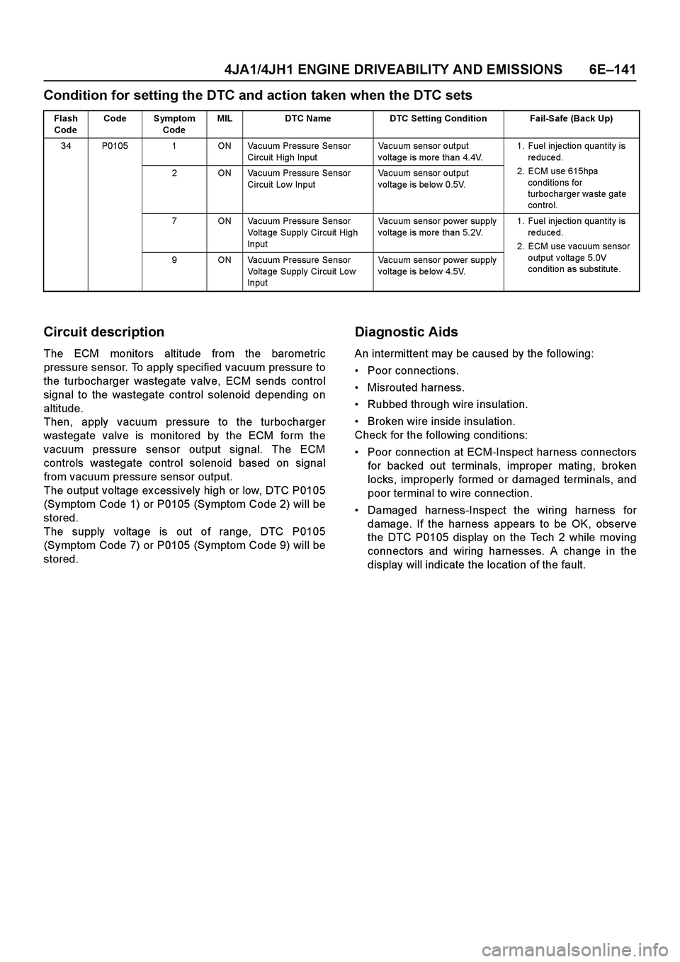
Condition for setting the DTC and action taken when the DTC sets
Circuit description
The ECM monitors altitude from the barometric
pressure sensor. To apply specified vacuum pressure to
the turbocharger wastegate valve, ECM sends control
signal to the wastegate control solenoid depending on
altitude.
Then, apply vacuum pressure to the turbocharger
wastegate valve is monitored by the ECM form the
vacuum pressure sensor output signal. The ECM
controls wastegate control solenoid based on signal
from vacuum pressure sensor output.
The output voltage ex cessively high or low, DTC P0105
(Symptom Code 1) or P0105 (Symptom Code 2) will be
stored.
The supply voltage is out of range, DTC P0105
(Symptom Code 7) or P0105 (Symptom Code 9) will be
stored.
Diagnostic Aids
An intermittent may be caused by the following:
Poor connections.
Misrouted harness.
Rubbed through wire insulation.
Broken wire inside insulation.
Check for the following conditions:
Poor connection at ECM-Inspect harness connectors
for backed out terminals, improper mating, broken
locks, improperly formed or damaged terminals, and
poor terminal to wire connection.
Damaged harness-Inspect the wiring harness for
damage. If the harness appears to be OK, observe
the DTC P0105 display on the Tech 2 while moving
connectors and wiring harnesses. A change in the
display will indicate the location of the fault.
Flash
CodeCode Symptom
CodeMIL DTC Name DTC Setting Condition Fail-Safe (Back Up)
34 P0105 1 ON Vacuum Pressure Sensor
Circuit High InputVacuum sensor output
voltage is more than 4.4V.1. Fuel injection quantity is
r e d u c e d .
2. ECM use 615hpa
conditio ns for
turbo cha rge r wa ste gate
contro l. 2 ON Vacuum Pressure Sensor
Circuit Low InputVacuum sensor output
voltage is below 0.5V.
7 ON Vacuum Pressure Sensor
Volta ge Supply Circuit High
InputVacuum senso r po wer supply
voltage is more than 5.2V.1. Fuel injection quantity is
r e d u c e d .
2. ECM use vacuum sensor
output voltage 5.0V
condition as substitute. 9 ON Vacuum Pressure Sensor
Volta ge Supply Circuit Lo w
InputVacuum senso r po wer supply
voltage is below 4.5V.
Page 1525 of 4264
4JA1/4JH1 ENGINE DRIVEABILITY AND EMISSIONS 6E –153
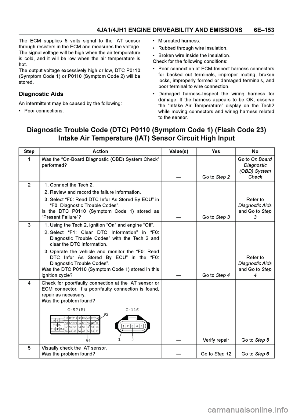
The ECM supplies 5 volts signal to the IAT sensor
through resisters in the ECM and measures the voltage.
The signal voltage will be high when the air temperature
is cold, and it will be low when the air temperature is
hot.
The output voltage ex cessively high or low, DTC P0110
(Symptom Code 1) or P0110 (Symptom Code 2) will be
stored.
Diagnostic Aids
An intermittent may be caused by the following:
Poor connections.
Misrouted harness.
Rubbed through wire insulation.
Broken wire inside the insulation.
Check for the following conditions:
Poor connection at ECM-Inspect harness connectors
for backed out terminals, improper mating, broken
locks, improperly formed or damaged terminals, and
poor terminal to wire connection.
Damaged harness-Inspect the wiring harness for
damage. If the harness appears to be OK, observe
the “Intake Air Temperature ” display on the Tech2
while moving connectors and wiring harness related
to the sensor.
Diagnostic Trouble Code (DTC) P0110 (Sy mptom Code 1) (Flash Code 23)
Intake Air Temperature (IAT) Sensor Circuit High Input
Step Action Value(s) Yes No
1Was the “On-Board Diagnostic (OBD) System Check ”
performed?
— Go to Step 2 Go to
On Board
Diagnostic
(OBD) System Check
2 1. Connect the Tech 2. 2. Review and record the failure information.
3. Select “F0: Read DTC Infor As Stored By ECU ” in
“ F0: Diagnostic Trouble Codes ”.
Is the DTC P0110 (Symptom Code 1) stored as
“ Present Failure ”? —Go to Step 3 Refer to
Diagnostic Aids and Go to Step
3
3 1. Using the Tech 2, ignition “On ” and engine “Off ”.
2. Select “F1: Clear DTC Information ” in “F0:
Diagnostic Trouble Codes ” with the Tech 2 and
clear the DTC information.
3. Operate the vehicle and monitor the “F0: Read
DTC Infor As Stored By ECU ” in the “F0:
Diagnostic Trouble Codes ”.
Was the DTC P0110 (Symptom Code 1) stored in this
ignition cycle? —Go to Step 4 Refer to
Diagnostic Aids and Go to Step
4
4 Check for poor/faulty connection at the IAT sensor or ECM connector. If a poor/faulty connection is found,
repair as necessary.
Was the problem found?
— Verify repair Go to Step 5
5 Visually check the IAT sensor. Was the problem found? —Go to Step 12 Go to Step 6
92
84
1 3
C-116
C-57(B)
Page 1533 of 4264
4JA1/4JH1 ENGINE DRIVEABILITY AND EMISSIONS 6E –161
a high resistance.
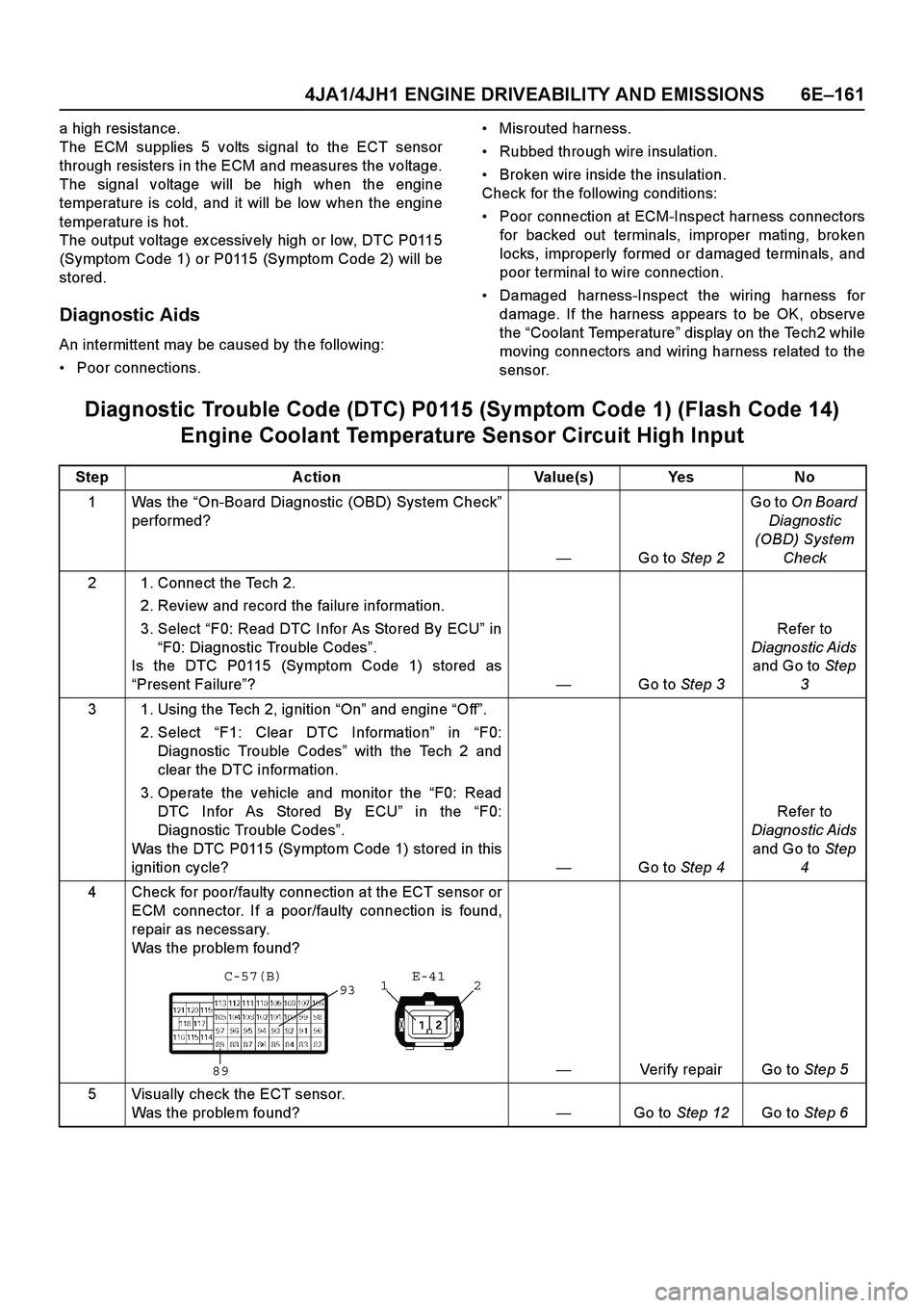
The ECM supplies 5 volts signal to the ECT sensor
through resisters in the ECM and measures the voltage.
The signal voltage will be high when the engine
temperature is cold, and it will be low when the engine
temperature is hot.
The output voltage ex cessively high or low, DTC P0115
(Symptom Code 1) or P0115 (Symptom Code 2) will be
stored.
Diagnostic Aids
An intermittent may be caused by the following:
Poor connections.
Misrouted harness.
Rubbed through wire insulation.
Broken wire inside the insulation.
Check for the following conditions:
Poor connection at ECM-Inspect harness connectors
for backed out terminals, improper mating, broken
locks, improperly formed or damaged terminals, and
poor terminal to wire connection.
Damaged harness-Inspect the wiring harness for
damage. If the harness appears to be OK, observe
the “Coolant Temperature ” display on the Tech2 while
moving connectors and wiring harness related to the
sensor.
Diagnostic Trouble Code (DTC) P0115 (Sy mptom Code 1) (Flash Code 14)
Engine Coolant Temperature Sensor Circuit High Input
Step Action Value(s) Yes No
1Was the “On-Board Diagnostic (OBD) System Check ”
performed?
— Go to Step 2 Go to
On Board
Diagnostic
(OBD) System Check
2 1. Connect the Tech 2. 2. Review and record the failure information.
3. Select “F0: Read DTC Infor As Stored By ECU ” in
“ F0: Diagnostic Trouble Codes ”.
Is the DTC P0115 (Symptom Code 1) stored as
“ Present Failure ”? —Go to Step 3 Refer to
Diagnostic Aids and Go to Step
3
3 1. Using the Tech 2, ignition “On ” and engine “Off ”.
2. Select “F1: Clear DTC Information ” in “F0:
Diagnostic Trouble Codes ” with the Tech 2 and
clear the DTC information.
3. Operate the vehicle and monitor the “F0: Read
DTC Infor As Stored By ECU ” in the “F0:
Diagnostic Trouble Codes ”.
Was the DTC P0115 (Symptom Code 1) stored in this
ignition cycle? —Go to Step 4 Refer to
Diagnostic Aids and Go to Step
4
4 Check for poor/faulty connection at the ECT sensor or ECM connector. If a poor/faulty connection is found,
repair as necessary.
Was the problem found?
— Verify repair Go to Step 5
5 Visually check the ECT sensor. Was the problem found? —Go to Step 12 Go to Step 6
932
1
89 E-41
C-57(B)